1991 ACURA NSX power steering
[x] Cancel search: power steeringPage 407 of 1640
Electrical Power Steering (EPS)
Outline
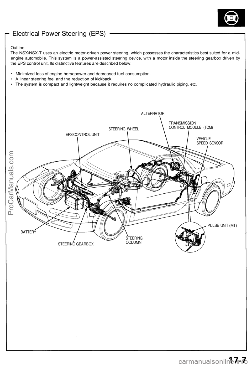
The NSX/NSX-T uses an electric motor-driven power steering, which possesses the characteristics best suited for a mid-
engine automobile. This system is a power-assisted steering device, with a motor inside the steering gearbox driven by
the EPS control unit. Its distinctive features are described below:
• Minimized loss of engine horsepower and decreased fuel consumption.
• A linear steering feel and the reduction of kickback.
• The system is compact and lightweight because it requires no complicated hydraulic piping, etc.
ALTERNATOR
TRANSMISSION
CONTROL MODULE (TCM)
EPS CONTROL UNIT
VEHICLE
SPEED SENSOR
PULSE UNIT (MT)
BATTERY
STEERING GEARBOX
STEERING WHEEL
STEERING
COLUMNProCarManuals.com
Page 408 of 1640
System Description
Major Components
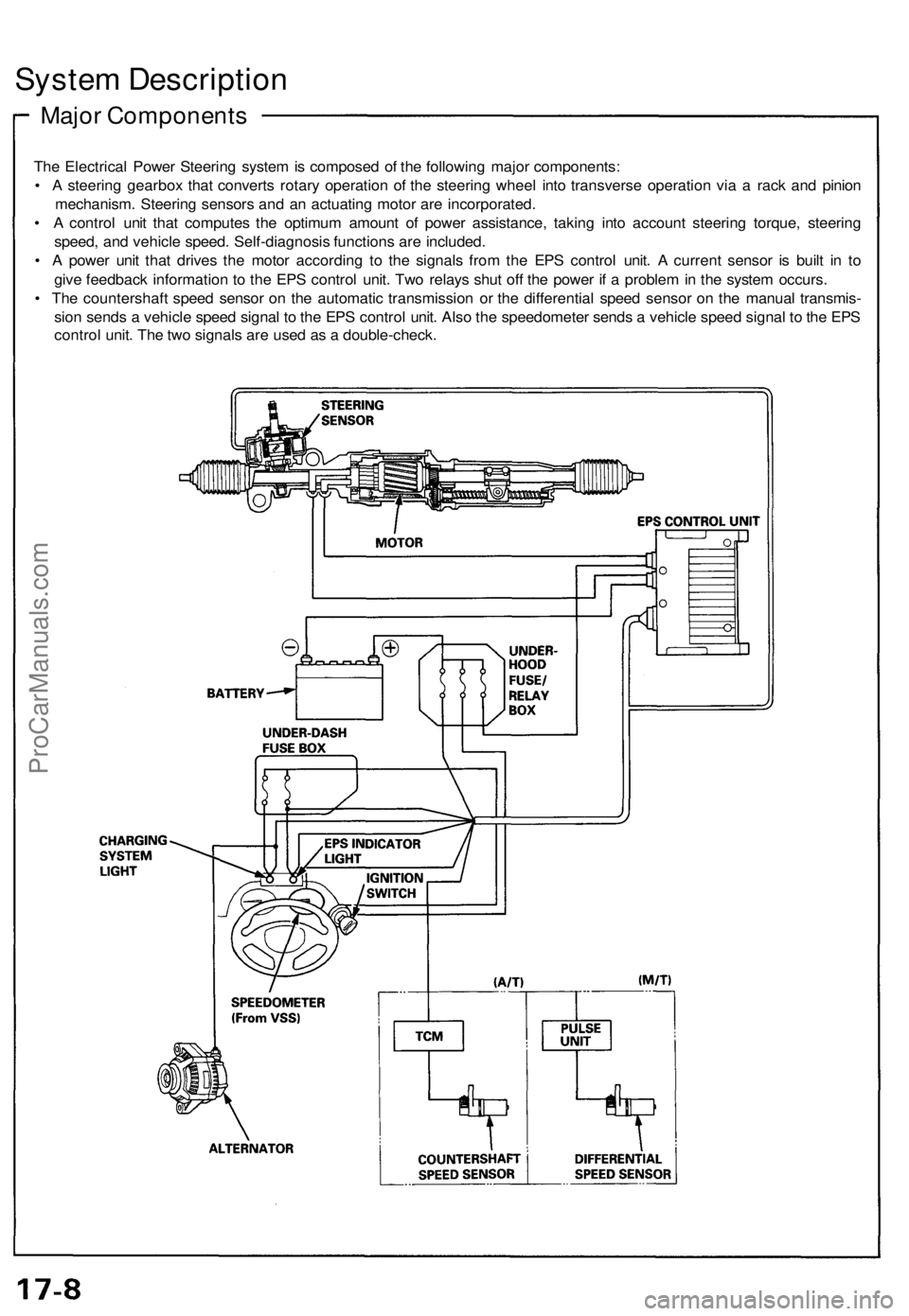
The Electrical Power Steering system is composed of the following major components:
• A steering gearbox that converts rotary operation of the steering wheel into transverse operation via a rack and pinion
mechanism. Steering sensors and an actuating motor are incorporated.
• A control unit that computes the optimum amount of power assistance, taking into account steering torque, steering
speed, and vehicle speed. Self-diagnosis functions are included.
• A power unit that drives the motor according to the signals from the EPS control unit. A current sensor is built in to
give feedback information to the EPS control unit. Two relays shut off the power if a problem in the system occurs.
• The countershaft speed sensor on the automatic transmission or the differential speed sensor on the manual transmis-
sion sends a vehicle speed signal to the EPS control unit. Also the speedometer sends a vehicle speed signal to the EPS
control unit. The two signals are used as a double-check.ProCarManuals.com
Page 411 of 1640
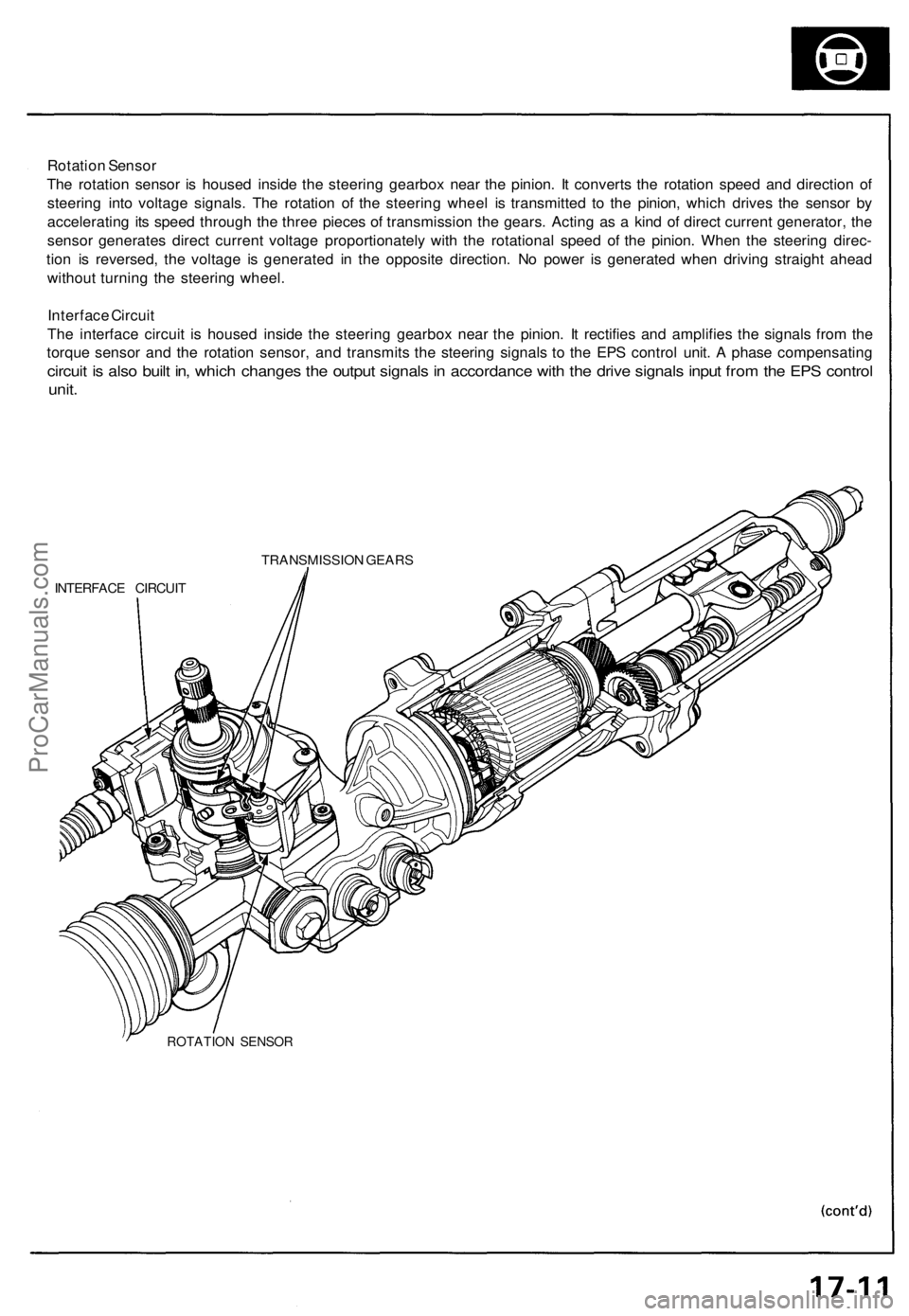
Rotation Sensor
The rotation sensor is housed inside the steering gearbox near the pinion. It converts the rotation speed and direction of
steering into voltage signals. The rotation of the steering wheel is transmitted to the pinion, which drives the sensor by
accelerating its speed through the three pieces of transmission the gears. Acting as a kind of direct current generator, the
sensor generates direct current voltage proportionately with the rotational speed of the pinion. When the steering direc-
tion is reversed, the voltage is generated in the opposite direction. No power is generated when driving straight ahead
without turning the steering wheel.
Interface Circuit
The interface circuit is housed inside the steering gearbox near the pinion. It rectifies and amplifies the signals from the
torque sensor and the rotation sensor, and transmits the steering signals to the EPS control unit. A phase compensating
circuit is also built in, which changes the output signals in accordance with the drive signals input from the EPS control
unit.
TRANSMISSION GEARS
INTERFACE CIRCUIT
ROTATION SENSORProCarManuals.com
Page 414 of 1640
System Description
Function and Operation
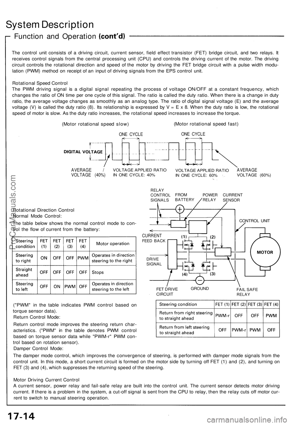
The control unit consists of a driving circuit, current sensor, field effect transistor (FET) bridge circuit, and two relays. It
receives control signals from the central processing unit (CPU) and controls the driving current of the motor. The driving
circuit controls the rotational direction and speed of the motor by driving the FET bridge circuit with a pulse width modu-
lation (PWM) method on receipt of an input of driving signals from the EPS control unit.
Rotational Speed Control
The PWM driving signal is a digital signal repeating the process of voltage ON/OFF at a constant frequency, which
changes the ratio of ON time per one cycle of this signal. The ratio is called the duty ratio. When there is a change in duty
ratio, the average voltage changes as smoothly as an analog type. The ratio of digital signal voltage (E) and the average
voltage (V) is called the duty ratio (8). Its relationship is expressed by V = E x 8. When the duty ratio is low, the rotational
speed of motor is slow. As the duty ratio increases, the rotational speed increases to increase the torque.
(Motor rotational speed slow)
ONE CYCLE
(Motor rotational speed fast)
ONE CYCLE
AVERAGE /
VOLTAGE (40%)
VOLTAGE APPLIED RATIO
IN ONE CYCLE: 40%
RELAY
CONTROL
SIGNALS
VOLTAGE APPLIED RATIO
IN ONE CYCLE: 60%
AVERAGE
VOLTAGE (60%)
FROM
BATTERY
POWER
RELAY
CURRENT
SENSOR
Rotational Direction Control
Normal Mode Control:
The table below shows the normal control mode to con-
trol the flow of current from the battery:
CURRENT
FEED BACK
DRIVE
SIGNAL
FET DRIVE
CIRCUIT
GROUND
FAIL SAFE
RELAY
("PWM" in the table indicates PWM control based on
torque sensor data).
Return Control Mode:
Return control mode improves the steering return char-
acteristics. ("PWM" in the table denotes PWM control
based on torque sensor data while "PWM-r" PWM con-
trol based on rotation sensor).
Damper Control Mode:
The damper mode control, which improves the convergence of steering, is performed with damper mode signals from the
control unit. In this mode, a short current circuit is formed on the motor side by turning off FET (1) and (2), and turning on
FET (3) and (4), which suppresses the returning speed of the steering.
Motor Driving Current Control
A current sensor, power relay and fail-safe relay are built into the control unit. The current sensor detects motor driving
current. If there is a problem in the system, a cut-off signal is sent from the CPU to relay, then the relay cuts off motor cur-
rent to switch to manual steering operation.
CONTROL UNITProCarManuals.com
Page 420 of 1640
Troubleshooting Precautions
EPS Indicator Light
Under normal conditions, the EPS indicator light in the gauge assembly comes on when the ignition switch is turned to
the ON (II) position, then goes off after the engine is started. This indicates that the bulb and its circuits are operating cor-
rectly. If there is any trouble in the system, the EPS indicator light turns on during driving, and the power steering assist is
turned off. When the EPS indicator light comes on, the control unit memorizes the DTC. In this case, the control unit does
not activate the EPS system after the engine starts again but it keeps the EPS indicator light on.
Diagnostic Trouble Code (DTC)
• The lowest DTC is indicated first.
• The DTCs continue blinking until the ignition switch is turned off.
• The DTCs are erased from the control unit when the EPS control unit VBU power supply or connector is disconnected.
• The EPS system can be reset and the control unit's memory can be erased by disconnecting the CLOCK (7.5 A) fuse for
more than ten seconds.
Self-diagnosis:
The CPU (central processing unit) controls the following when it detects a problem during self-diagnosis:
1. Turns the EPS indicator light ON to alert the driver.
2. Power assist stops, and normal manual steering operation resumes (except DTC 21 and DTC 33).
3. The EPS control unit memorizes the diagnostic trouble code (DTC).
4. After the DTC is stored in the control unit, the CPU stops self-diagnosis.
Troubleshooting:
• Before starting the troubleshooting, clear the DTC by disconnecting the CLOCK (7.5 A) fuse for ten seconds or more,
and test-drive the car. Check that the symptom of the trouble appears again, and then troubleshoot. If the problem is an
intermittent problem, the system does not become active after the engine starts even though the problem is solved.
• When both EPS indicator light and A/T "D" indicator light come on, perform the A/T troubleshooting first.
• When the customer's reported problem cannot be verified in the car, ask the customer about the conditions when the
EPS indicator light came ON, then test-drive the car under those conditions, if possible. If the EPS indicator light does
not come ON during the test, check for loose connections or poor contacts at the connectors by wiggling the harness,
etc.
• The connector terminal numbers are viewed from the wire side for the female terminals and from the terminal side for
the male terminals.
• After the repair, test-drive the car and check that the EPS indicator light does not come ON again during the test. (Refer
to the Symptom-to-System Chart for diagnostic period.)ProCarManuals.com
Page 425 of 1640
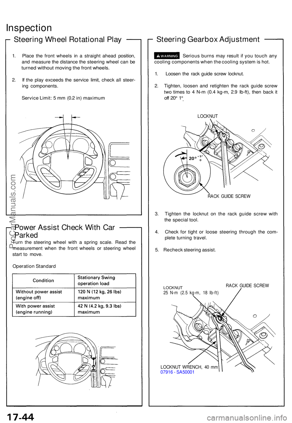
Inspection
Steering Whee l Rotationa l Pla y
1. Plac e th e fron t wheel s i n a straigh t ahea d position ,
an d measur e th e distanc e th e steerin g whee l ca n b e
turne d withou t movin g th e fron t wheels .
2. I f th e pla y exceed s th e servic e limit , chec k al l steer -
in g components .
Servic e Limit : 5 m m (0. 2 in ) maximu m
Power Assis t Chec k Wit h Ca r
Parke d
Turn th e steerin g whee l wit h a sprin g scale . Rea d th e
measuremen t whe n th e fron t wheel s o r steerin g whee l
star t t o move .
Operatio n Standar d
Steering Gearbo x Adjustmen t
Serious burn s ma y resul t i f yo u touc h an y
coolin g component s whe n th e coolin g syste m is hot .
1 . Loose n th e rac k guid e scre w locknut .
2 . Tighten , loose n an d retighte n th e rac k guid e scre w
tw o time s t o 4 N- m (0. 4 kg-m , 2. 9 Ib-ft) , the n bac k i t
of f 20 ° 1 °
LOCKNU T
RACK GUID E SCRE W
3. Tighte n th e locknu t o n th e rac k guid e scre w wit h
th e specia l tool .
4 . Chec k fo r tigh t o r loos e steerin g throug h th e com -
plet e turnin g travel .
5 . Rechec k steerin g assist .
LOCKNU T25 N- m (2. 5 kg-m , 1 8 Ib-ft )
RACK GUID E SCRE W
LOCKNU T WRENCH , 4 0 m m0791 6 - SA5000 1
ProCarManuals.com
Page 965 of 1640
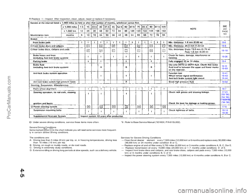
R-Replace I — Inspect After inspection, clean, adjust, repair or replace if necessary.
sec
and
PAGE
NO
19-6 19-8
19-18
19-26
19-4
19-10
19-69
19-41
19-43 19-44
19-62
18-7
17-21
('93-'96)
('94-'96)
17-60('94-'96)
('94-'96)
17-6
18-14
18-30
Under severe driving conditions, service these items more often.
Severe Driving Conditions
Items marked or in the chart indicate you will need some services more frequent-
ly in certain severe driving conditions.
The conditions are:
A: Driving loss than 5 miles (8 km) per trip, or, in freezing temperatures, driving less than 10 miles (16 km) per trip.
B: Driving, on rough or muddy roads, or de-iced roads.
C: Driving in extremely dusty conditions.
D: Extensive idling or driving long periods at slow speeds, such as a delivery vehicle. *6 : Ruler to Base Service Manual ('93 NSX, P/N 61SL002).
Services for Severe Driving Conditions
—
Clean
the air
cleaner
element
every
7,500 miles
(12,000
kml or 6
months
and
replace every
30,000
miles (48,000 km) or 24 months under condition B or C,
— Replace engine oil and oil filter every 3,750 miles (6,000 km) or\
3 months under conditions A, B, C, Dor E.
— Replace transmission oil every 15,000 miles (24,000 km) or 1 7. months under conditions D of E.
— Inspect front brake discs and calipers, and rear brake dises, calipers and pads every 7,500 miles (12,000
km) or 6 months under conditions B, C of D.
— Inspect the power steering system every 7,500 miles (12,000 km) or 6 months under conditions A, B or C.ProCarManuals.com
Page 973 of 1640
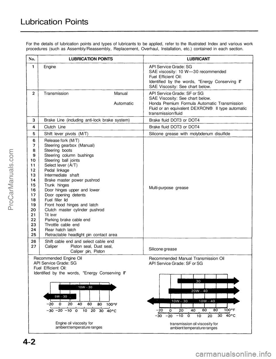
Lubrication Points
For the details of lubrication points and types of lubricants to be applied, refer to the Illustrated Index and various workprocedures (such as Assembly/Reassembly, Replacement, Overhaul, Installation, etc.) contained in each section.
No.
LUBRICATION POINTS
LUBRICANT
Engine
Transmission
Manual
Automatic
Brake Line (including anti-lock brake system)
Clutch Line Shift lever pivots (M/T)Release fork (M/T)Steering gearbox (Manual)
Steering boots Steering column bushings
Steering ball jointsSelect lever (A/T)
Pedal linkage Intermediate shaft
Brake master power pushrod
Trunk hinges Door hinges upper and lower
Door opening detents
Fuel filler lid
Front hood hinges and latch
Clutch master cylinder pushrod
Tilt lever
Parking brake cable end
Throttle cable end Rear hatch latchRetractable headlight pin contact area
Shift cable end and select cable end
Caliper Piston seal, Dust seal, Caliper pin, Piston
Recommended Engine Oil
API Service Grade: SG Fuel Efficient Oil:
Identified by the words, "Energy Conserving II" API Service Grade: SG
SAE viscosity: 10 W—30 recommended
Fuel Efficient Oil:
Identified by the words, "Energy Conserving II"
SAE Viscosity: See chart below.
API Service Grade: SF or SG SAE Viscosity: See chart below.
Honda Premium Formula Automatic Transmission
Fluid or an equivalent DEXRON® II type automatic
transmission fluid
Brake fluid DOT3 or DOT4
Brake fluid DOT3 or DOT4
Silicone grease with molybdenum disulfide
Multi-purpose grease
Silicone grease Recommended Manual Transmission Oil
API Service Grade: SF or SG
transmission oil viscosity forambient temperature ranges
Engine oil viscosity for
ambient temperature rangesProCarManuals.com