Page 1339 of 1640
Component Location
Index
NOTE:
EPS CONTROL UNITReplacement, page 17-74
POWER UNIT
Replacement, page 17-73
STEERING WHEEL/
AIRBAG ASSEMBLYRemoval, page 17-8
Disassembly, page 17-9
Installation, page 17-10
STEERING COLUMN
Removal, page 17-12
Inspection, page 17-14
Installation, page 17-15
STEERING GEARBOX Removal/Installation, page 17-64
Illustrated Index, page 17-68
Pinion Preload Inspection, page 17-69
Rack Guide Screw Adjustment, page 17-69
If an intact airbag assembly has been removed from a scrapped car or has been found defective or damaged during
transit, storage or service, it should be deployed (see section 23).
Before removing the gearbox, remove the ignition key to lock the steering shaft.
After installing the gearbox, check the wheel alignment and adjust if necessary.ProCarManuals.com
Page 1340 of 1640
Power Steering
Gearbox Removal/Installation
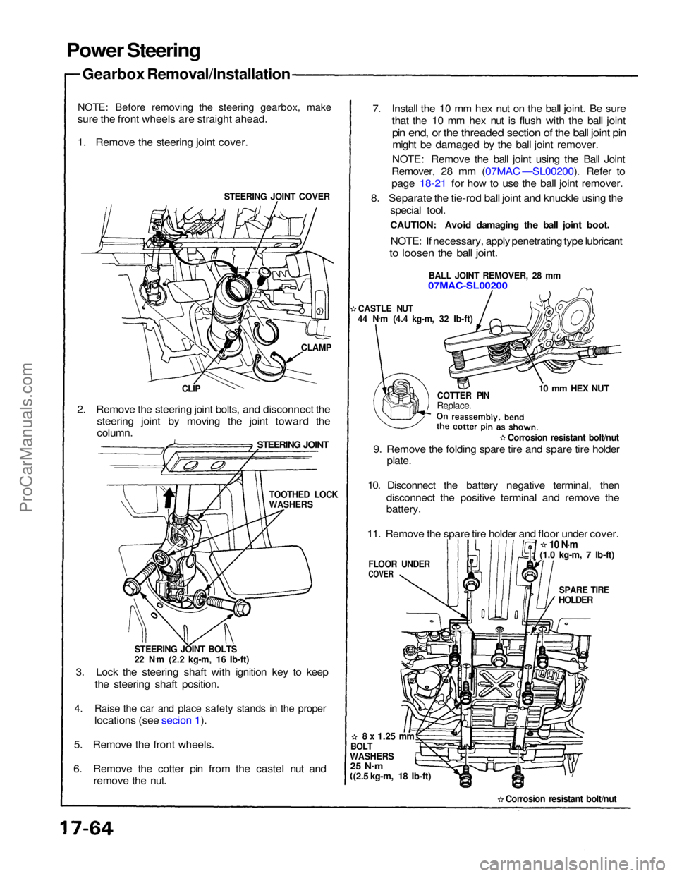
NOTE: Before removing the steering gearbox, make
sure the front wheels are straight ahead.
1. Remove the steering joint cover.
STEERING JOINT COVER
CLAMP
CLIP
2. Remove the steering joint bolts, and disconnect the steering joint by moving the joint toward the
STEERING JOINT
column.
STEERING JOINT BOLTS
22 N.
m (2.2 kg-m, 16 Ib-ft)
3. Lock the steering shaft with ignition key to keep the steering shaft position.
4. Raise the car and place safety stands in the proper
locations (see secion 1).
5. Remove the front wheels.
6. Remove the cotter pin from the castel nut and remove the nut. 7. Install the 10 mm hex nut on the ball joint. Be sure
that the 10 mm hex nut is flush with the ball joint
pin end, or the threaded section of the ball joint pin
might be damaged by the ball joint remover.
NOTE: Remove the ball joint using the Ball Joint
Remover, 28 mm (07MAC —SL00200). Refer to
page 18-21 for how to use the ball joint remover.
8. Separate the tie-rod ball joint and knuckle using the special tool.
CAUTION: Avoid damaging the ball joint boot.
NOTE: If necessary, apply penetrating type lubricant
to loosen the ball joint.
BALL JOINT REMOVER, 28 mm
07MAC-SL00200
CASTLE NUT
44 N .
m (4.4 kg-m, 32 Ib-ft)
COTTER PIN
Replace.
10 mm HEX NUT
Corrosion resistant bolt/nut
9. Remove the folding spare tire and spare tire holder plate.
10. Disconnect the battery negative terminal, then disconnect the positive terminal and remove the
battery.
11. Remove the spare tire holder and floor under cover.
10 N·m
SPARE TIRE
HOLDER
FLOOR UNDER
COVER
8 x
1.25
mm
BOLT
WASHERS
25 N .
m
(2.5 kg-m, 18 Ib-ft)
Corrosion resistant bolt/nut
TOOTHED LOCK
WASHERS
(1.0 kg-m, 7 Ib-ft)ProCarManuals.com
Page 1342 of 1640
Power SteeringGearbox Removal/Installation (cont'd)
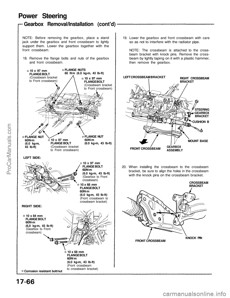
NOTE: Before removing the gearbox, place a stand
jack under the gearbox and front crossbeam to lightly
support them. Lower the gearbox together with the
front crossbeam.
18. Remove the flange bolts and nuts of the gearbox and front crossbeam.
FLANGE NUTS
60 N.m (6.0 kg-m, 43 Ib-ft)
10 x 97 mm
FLANGE BOLT (Crossbeam bracket
to Front crossbeam)
10 x 97 mm
FLANGE BOLT (Crossbeam bracket
to Front crossbeam)
FLANGE NUT
60N .
m
(6.0 kg-m,
43 Ib-ft)
10 x 97 mm
FLANGE BOLT
(Crossbeam bracket
to Front crossbeam)
LEFT SIDE:
RIGHT SIDE:
10 x 84 mm
FLANGE BOLT
60N .
m
(6.0 kg-m, 43 Ib-ft) (Gearbox to Front
crossbeam)
Corrosion resistant bolt/nut
10 x 68 mm
FLANGE BOLT
60N ·
m
(6.0 kg-m, 43 Ib-ft)
(Front crossbeam
to crossbeam bracket)
10 x 68 mm
FLANGE BOLT
60N ·
m
(6.0 kg-m, 43 Ib-ft)
(Front crossbeam to
crossbeam bracket)
10 x 97 mm
FLANGE BOLT
60N·m
(6.0 kg-m, 43 Ib-ft) (Gearbox to Front
crossbeam) 19. Lower the gearbox and front crossbeam with care
so as not to interfere with the radiator pipe.
NOTE: The crossbeam is attached to the cross-
beam bracket with knock pins. Remove the cross-
beam by lightly taping on it with a plastic hammer,
then remove the gearbox.
LEFT CROSSBEAM BRACKET
FRONT CROSSBEAM
GEARBOX
ASSEMBLY
20. When installing the crossbeam to the crossbeam bracket, be sure to align the holes in the crossbeam
with the knock pins on the crossbeam bracket.
CROSSBEAM
BRACKET
KNOCK PIN
FRONT CROSSBEAM RIGHT CROSSBEAM
BRACKET
STEERING
GEARBOX
BRACKET
CUSHION B
MOUNT BASE
FLANGE NUT
60N
·
m
(6.0 kg-m, 43 Ib-ft)ProCarManuals.com
Page 1344 of 1640
Power Steering
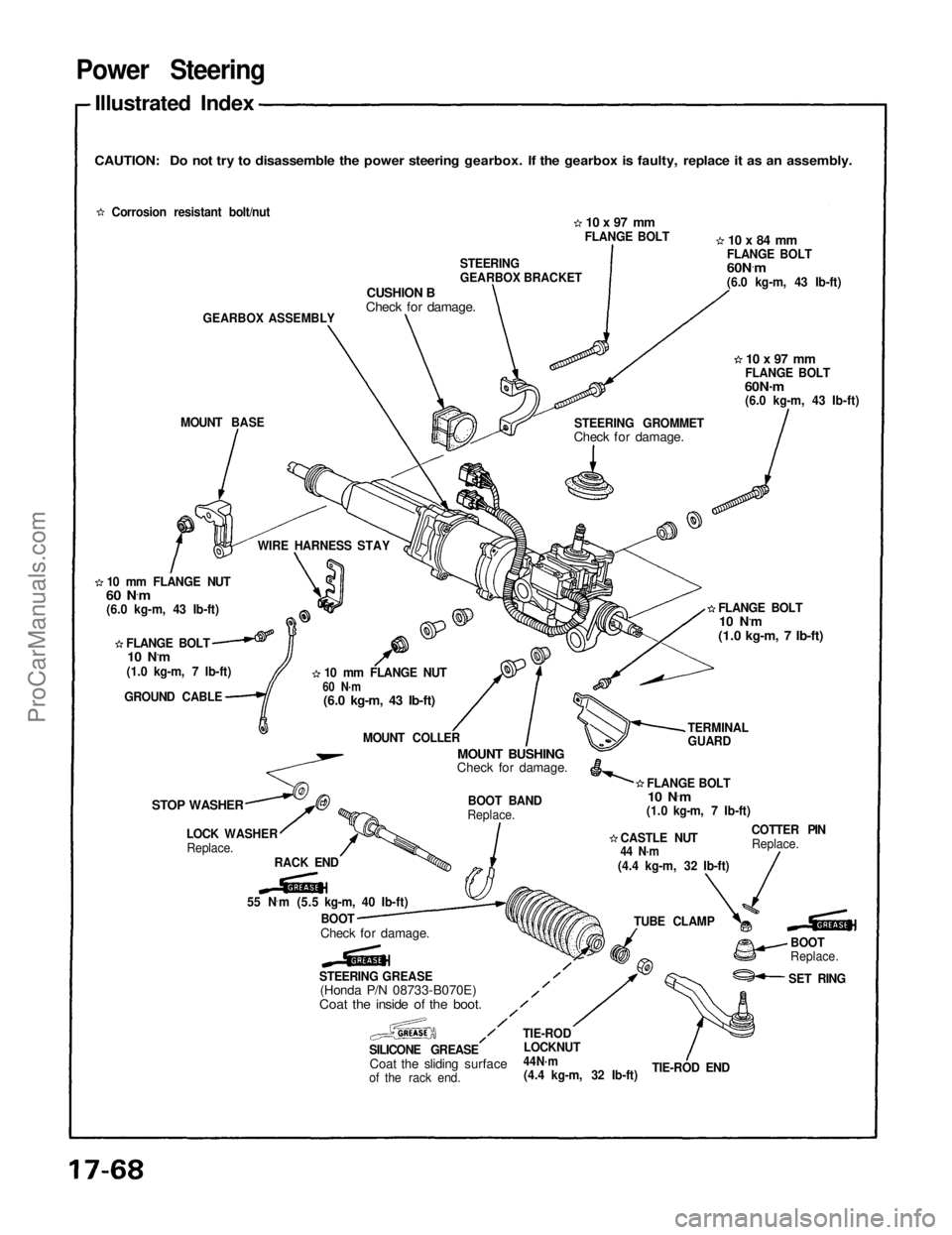
Illustrated Index
CAUTION: Do not try to disassemble the power steering gearbox. If the gearbox is faulty, replace it as an assembly.
Corrosion resistant bolt/nut
GEARBOX ASSEMBLY
MOUNT BASE
10 mm FLANGE NUT
60 N ·
m
(6.0 kg-m, 43 Ib-ft)
FLANGE BOLT
10 N.m
(1.0 kg-m, 7 Ib-ft)
GROUND CABLE
STOP WASHER
LOCK WASHERReplace.
RACK END
55 N ·
m (5.5 kg-m, 40 Ib-ft)
BOOT
Check for damage.
STEERING GREASE
(Honda P/N 08733-B070E)
Coat the inside of the boot.
SILICONE GREASE
Coat the sliding surface
of the rack end. TIE-ROD
LOCKNUT44N·m
(4.4 kg-m, 32 Ib-ft)
TIE-ROD END BOOT
Replace.
SET RING
TUBE CLAMP COTTER PIN
Replace.
CASTLE NUT
44 N·m
(4.4 kg-m, 32 Ib-ft)
FLANGE BOLT
10 N ·
m
(1.0 kg-m, 7 Ib-ft) TERMINAL
GUARDFLANGE BOLT
10 N.m
(1.0 kg-m, 7 Ib-ft)
10 x 97 mm
FLANGE BOLT
60N .
m
(6.0 kg-m, 43 Ib-ft)
STEERING GROMMET
Check for damage.
CUSHION B
Check for damage.
STEERING
GEARBOX BRACKET
10 x 97 mm
FLANGE BOLT
10 x 84 mm
FLANGE BOLT
60N ·
m
(6.0 kg-m, 43 Ib-ft)
WIRE HARNESS STAY 10 mm FLANGE NUT
60 N·m
(6.0 kg-m, 43 Ib-ft)
MOUNT COLLER
MOUNT BUSHING
Check for damage.
BOOT BAND
Replace.ProCarManuals.com
Page 1346 of 1640
Power Steering
Inspection (cont'd)
Retighten the locknut while holding the rack guide
screw with a wrench. Tie-rod installation:
5. Screw each rack end into the rack while holding the
lock washer so its tabs are in the slots in the rack
end.
NOTE: Install the stopper washer with the cham-
fered side facing out.
6. Tighten the rack end securely, then band the lock washer back against the flat on the flange as shown.
NOTE: Coat the stopper washer with grease suffi-
LOCKNUT
25 N.m (2.5 kg-m, 18 Ib-ft)
LOCKNUT WRENCH. 40 mm
07916-SA50001
RACK END
55 N.
m
(5.5 kg-m, 40 Ib-ft)
ciently.
RACK END
TAB
SLOT
STOPPER WASHER
LOCK WASHER
Installation
direction.
bends.ProCarManuals.com
Page 1348 of 1640
Power Steering
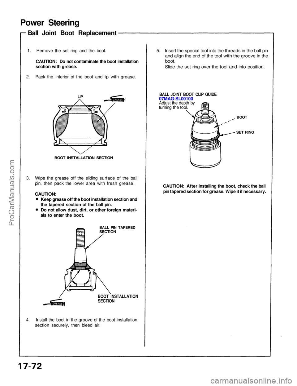
Ball Joint Boot Replacement
1. Remove the set ring and the boot. CAUTION: Do not contaminate the boot installation
section with grease.
2. Pack the interior of the boot and lip with grease.
5. Insert the special tool into the threads in the ball pin
and align the end of the tool with the groove in the
boot.
Slide the set ring over the tool and into position.
CAUTION: After installing the boot, check the ball pin tapered section for grease. Wipe it if necessary.
3. Wipe the grease off the sliding surface of the ball
pin, then pack the lower area with fresh grease.
CAUTION:
BOOT INSTALLATION SECTION
BALL PIN TAPERED
SECTION
4. Install the boot in the groove of the boot installation section securely, then bleed air.
BOOT INSTALLATION
SECTION
LIP
BALL JOINT BOOT CLIP GUIDE
07MAG-SL00100
Adjust the depth by
turning the tool.
BOOT
SET RING
Keep grease off the boot installation section and
the tapered section of the ball pin.
Do not allow dust, dirt, or other foreign materi-
als to enter the boot.ProCarManuals.com
Page 1362 of 1640
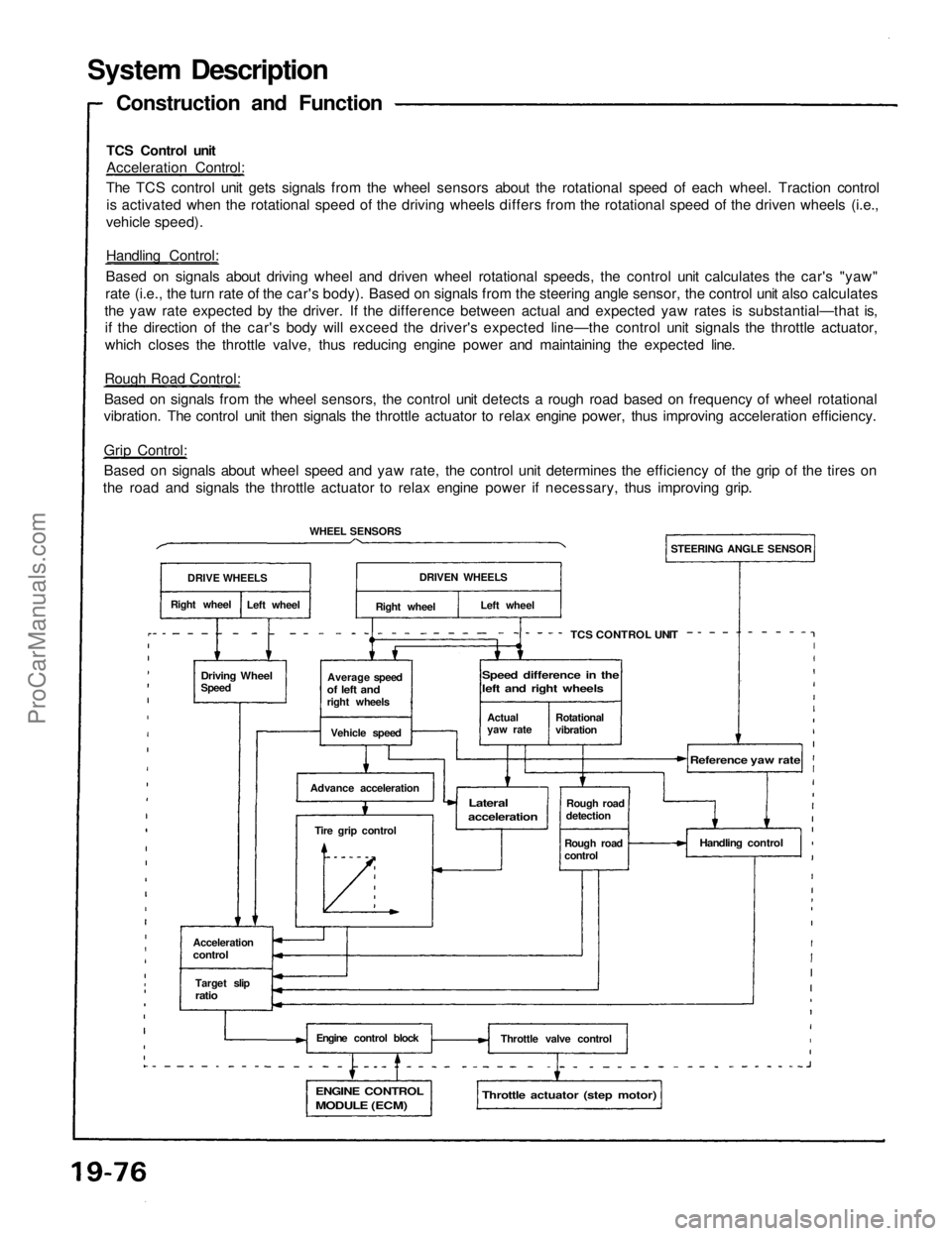
System Description
TCS Control unit
Acceleration Control:
The TCS control unit gets signals from the wheel sensors about the rotational speed of each wheel. Traction control
is activated when the rotational speed of the driving wheels differs from the rotational speed of the driven wheels (i.e.,
vehicle speed).
Handling Control:
Based on signals about driving wheel and driven wheel rotational speeds, the control unit calculates the car's "yaw"
rate (i.e., the turn rate of the car's body). Based on signals from the steering angle sensor, the control unit also calculates
the yaw rate expected by the driver. If the difference between actual and expected yaw rates is substantial—that is,
if the direction of the car's body will exceed the driver's expected line—the control unit signals the throttle actuator,
which closes the throttle valve, thus reducing engine power and maintaining the expected line.
Rough Road Control:
Based on signals from the wheel sensors, the control unit detects a rough road based on frequency of wheel rotational
vibration. The control unit then signals the throttle actuator to relax engine power, thus improving acceleration efficiency.
Grip Control:
Based on signals about wheel speed and yaw rate, the control unit determines the efficiency of the grip of the tires on
the road and signals the throttle actuator to relax engine power if necessary, thus improving grip.
Construction and Function
DRIVE WHEELS
Right wheel
Left wheel
WHEEL SENSORS
Driving Wheel
Speed
Average speed
of left and
right wheels
Vehicle speed
Advance acceleration
Tire grip control
Acceleration
control
Target slip
ratio
Engine control block
ENGINE CONTROL
MODULE (ECM)
Throttle actuator (step motor)
Throttle valve control
Handling control
Rough road
detection
Rough road
control
Reference yaw rate
Lateral
acceleration
TCS CONTROL UNIT
STEERING ANGLE SENSOR
DRIVEN WHEELS
Right wheel
Left wheel
Actual
yaw rate
Rotational
vibration
Speed difference in the
left and right wheelsProCarManuals.com
Page 1431 of 1640
Rear Window Defogger
Switch Light Bulb Replacement
1. Remove the steering column lower and upper covers.
2. Remove the four screws from the combination
switch.
3. Remove the rear window defogger switch (see previous page).
4. Remove the rear window defogger switch bulbs.
BULBS (0.91 W)
REAR WINDOW
DEFOGGER SWITCH Relay Test
1. Remove the defogger relay in the engine compart- ment fuse/relay box.
2. There should be continuity between the C and D terminals.
3. There should be continuity between the A and B terminals when power and ground are connected to
the C and D terminals.
There should be no continuity when power isdisconnected.ProCarManuals.com