1991 ACURA NSX engine oil
[x] Cancel search: engine oilPage 72 of 1640
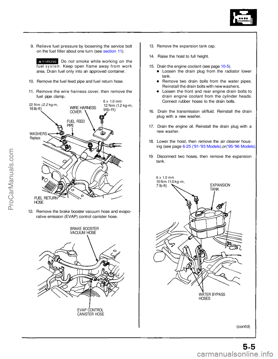
9. Relieve fuel pressure by loosening the service bolt
on the fuel filter about one turn (see section 11).
Do not smoke while working on the
fuel
system.
Keep open flame away from work
area. Drain fuel only into an approved container.
10. Remove the fuel feed pipe and fuel return hose.
11. Remove the wire harness cover, then remove the fuel pipe clamp.
22 N·m
(2.2 kg-m,
16 Ib-ft)
WIRE HARNESS
COVER
6 x 1.0 mm
12 N·m
(1.2 kg-m,
9 lb-ft)
FUEL FEED
PIPE
WASHERS
Replace.
FUEL RETURN
HOSE
12. Remove the brake booster vacuum hose and evapo- rative emission (EVAP) control canister hose.
BRAKE BOOSTER
VACUUM HOSE
EVAP CONTROL
CANISTER HOSE
13. Remove the expansion tank cap.
14. Raise the hoist to full height.
15. Drain the engine coolant (see page
10-5).
Loosen the drain plug from the radiator lower
tank. Remove two drain bolls from the water pipes.
Reinstall the drain bolts with new washers.
Loosen the front and rear engine drain bolts to
drain engine coolant from the cylinder heads.
Connect rubber hoses to the drain bolts.
16. Drain the transmission oil/fluid. Reinstall the drain plug with a new washer.
17. Drain the engine oil. Reinstall the drain plug with a
new washer.
18. Lower the hoist, then remove the air cleaner hous-
ing (see page 6-25 ('91-'93 Mode ls),or('95-'96 Models).
19. Disconnect two hoses, then remove the expansion
tank.
6 x 1.0 mm
10 N·m
11.0 kg-m,
7 lb-ft)
EXPANSION
TANK
WATER BYPASS
HOSES
(cont'd)ProCarManuals.com
Page 77 of 1640
Engine Removal/Installatio n
Removal
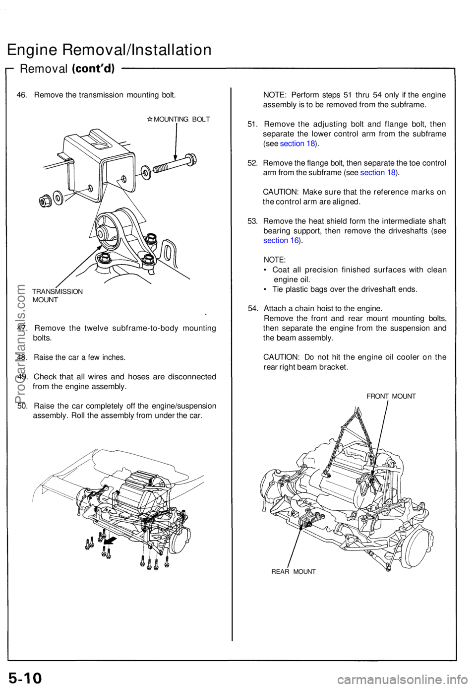
46. Remov e th e transmissio n mountin g bolt .
MOUNTIN G BOL T
TRANSMISSIO NMOUNT
47. Remov e th e twelv e subframe-to-bod y mountin g
bolts.
48. Rais e th e ca r a fe w inches .
49. Chec k tha t al l wire s an d hose s ar e disconnecte d
from th e engin e assembly .
50 . Rais e th e ca r completel y of f th e engine/suspensio n
assembly . Rol l th e assembl y fro m unde r th e car . NOTE
: Perfor m step s 5 1 thr u 5 4 onl y i f th e engin e
assembl y is t o b e remove d fro m th e subframe .
51 . Remov e th e adjustin g bol t an d flang e bolt , the n
separat e th e lowe r contro l ar m fro m th e subfram e
(se e sectio n 18 ).
52 . Remov e th e flang e bolt , the n separat e th e to e contro l
ar m fro m th e subfram e (se e sectio n 18 ).
CAUTION : Mak e sur e tha t th e referenc e mark s o n
th e contro l ar m ar e aligned .
53 . Remov e th e hea t shiel d for m th e intermediat e shaf t
bearin g support , the n remov e th e driveshaft s (se e
sectio n 16 ).
NOTE :
• Coa t al l precisio n finishe d surface s wit h clea n
engin e oil .
• Ti e plasti c bag s ove r th e driveshaf t ends .
54 . Attac h a chai n hois t t o th e engine .
Remov e th e fron t an d rea r moun t mountin g bolts ,
the n separat e th e engine from th e suspensio n an d
th e bea m assembly .
CAUTION : D o no t hi t th e engin e oi l coole r o n th e
rea r righ t bea m bracket .
FRONT MOUN T
REAR MOUN T
ProCarManuals.com
Page 80 of 1640
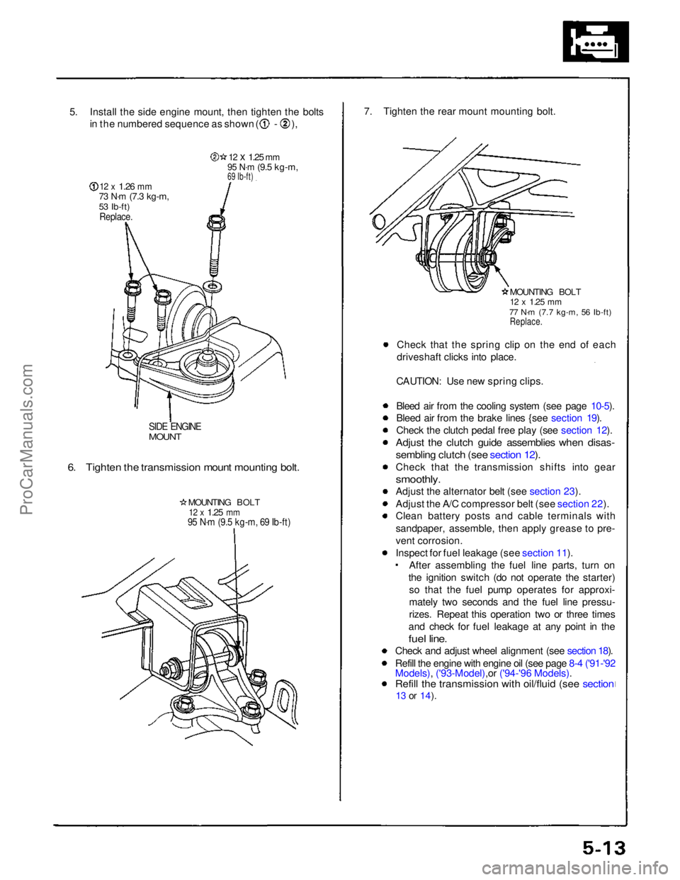
5. Install the side engine mount, then tighten the bolts
in the numbered sequence as shown ( - ),
12 x
1.26
mm
73 N·m
(7.3 kg-m,
53 Ib-ft)
Replace.
12 x
1.25
mm
95 N·m
(9.5 kg-m,
69 Ib-ft)
SIDE ENGINE
MOUNT
6. Tighten the transmission mount mounting bolt.
MOUNTING BOLT
12 x
1.25
mm
95 N·m (9.5 kg-m, 69 Ib-ft)
7. Tighten the rear mount mounting bolt.
MOUNTING BOLT
12 x
1.25
mm
77 N·m (7.7 kg-m, 56 Ib-ft)
Replace.
Check that the spring clip on the end of each
driveshaft clicks into place.
CAUTION: Use new spring clips.
Bleed air from the cooling system (see page 10-5).
Bleed air from the brake lines {see section 19).
Check the clutch pedal free play (see section 12).
Adjust the clutch guide assemblies when disas-
sembling clutch (see section 12).
Check that the transmission shifts into gear
smoothly.
Adjust the alternator belt (see section 23).
Adjust the A/C compressor belt (see section 22).
Clean battery posts and cable terminals with
sandpaper, assemble, then apply grease to pre-
vent corrosion.
Inspect for fuel leakage (see section 11). After assembling the fuel line parts, turn on
the ignition switch (do not operate the starter) so that the fuel pump operates for approxi-
mately two seconds and the fuel line pressu-
rizes. Repeat this operation two or three times
and check for fuel leakage at any point in the
fuel line.
Check and adjust wheel alignment (see section 18).
Refill the engine with engine oil (see page 8-4 ('91-'92
Models), ('93-Model),or ('94-'96 Models).
Refill the transmission with oil/fluid (see section
13 or
14).ProCarManuals.com
Page 89 of 1640

Timing Belt
Inspection
1. Remove the ignition coil covers and harness clamps.
2. Disconnect the connectors, then remove the ignition
coils.
3. Remove the cylinder head covers,
4. Inspect the timing belt for cracks and coolant or oil soaking.
NOTE:
Replace the belt if coolant or oil soaked.
Remove any oil or solvent that gets on the belt.
Inspect this area
for wear.
Rotate pulley and
Inspect belt.
Tension Adjustment
CAUTION:
Always adjust timing belt tension with the engine cold
Do not rotate the crankshaft when the adjusting bolt
is loose (the timing belt will skid over the teeth of
the rear intake caimshaft pulley).
Adjust the belt tension only when the belt has been
removed and reinstalled or replaced.
NOTE:
Tensioner is spring-loaded to apply proper tension to
the belt automatically after making the following ad-
justment. Inspect the timing belt before adjusting the belt
tension.
Always rotate the crankshaft clockwise. Rotating it
counterclockwise may result in improper adjustment
of the belt tension or cause the belt to jump a tooth
on the camshaft pulleys.
Install the timing beIt with the No. 1 piston at TDC
(see pages 6-18 ('91-'93) or ('94-'96),19 ('91-'93)
or ('94-'96) Remove the slack in the sequence of , and
by turning each camshaft pulley slightly.
Loosen the timing belt adjusting bolt 180° (the slack
at should be eliminated).
Then, tighten the timing belt adjusting bolt.
Verify that No. 1 piston is at TDC (see page 6-19).
Rotate the crankshaft clockwise nine teeth on the
camshaft pulley (The blue mark on the crankshaft pul- ley should line up with the pointer on lower cover).
Loosen
the
timing
belt
adjusting
bolt.
Retighten the adjusting bolt, torque to 43 N·m (4.3
kg-m, 31 Ib-fl).
Direction
of rotation
POINTER ON
LOWER COVER
ADJUSTING BOLT
43N·m (4.3 kg-m,
31 Ib-ft)
BLUE MARK
TDC MARK
ProCarManuals.com
Page 90 of 1640
Removal
NOTE:
Before removing the belt, turn the crankshaft pulley
so the No. 8 piston is at top dead center (TDC) (see
page 6-19 ('91-'93) or ('94-'96)
Inspect the water pump after removing the timing
belt (see page 10-11).
If it is to be reused, mark the direction of rotation on
the belt.
1. Disconnect the battery negative terminal first, then the positive terminal,
2. Remove the right rear wheel/tire.
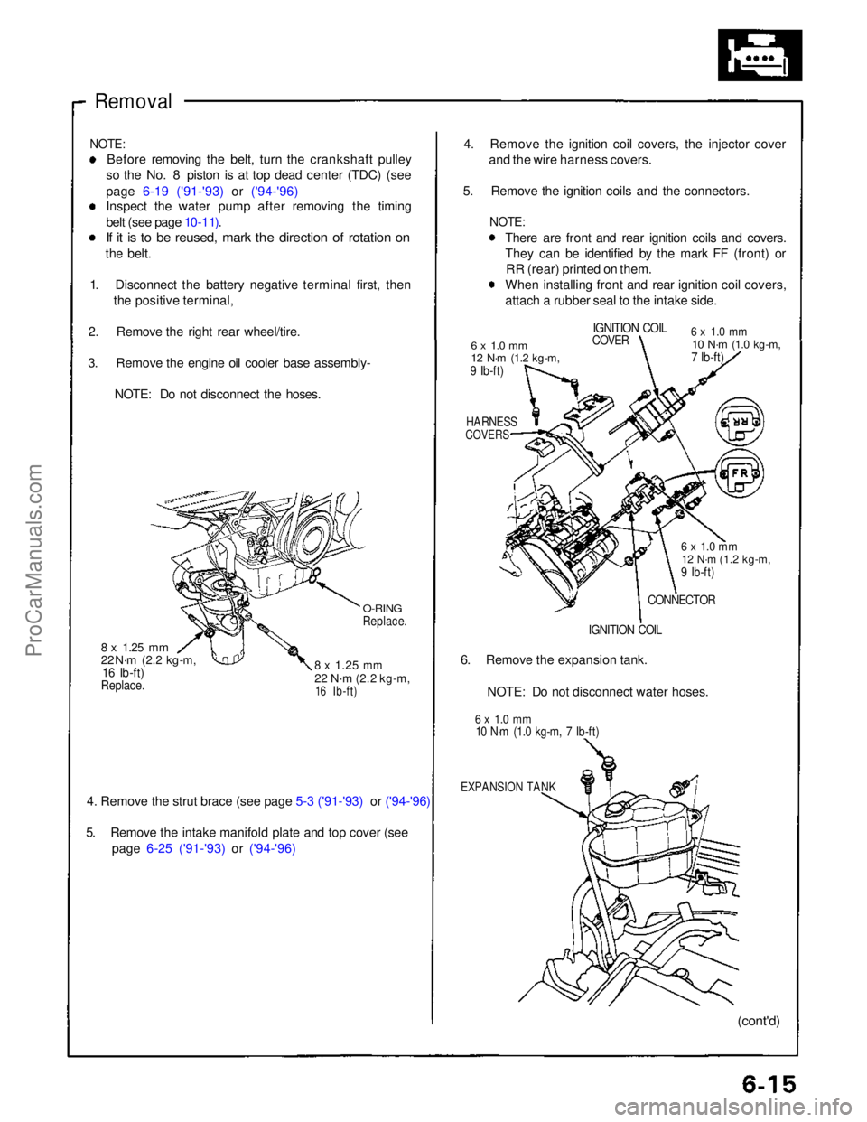
3. Remove the engine oil cooler base assembly- NOTE: Do not disconnect the hoses.
O-RING
Replace.
8 x
1.25
mm
22 N·m
(2.2 kg-m,
16 Ib-ft)
8 x
1.25
mm
22 N·m
(2.2 kg-m,
16 Ib-ft)
Replace.
4. Remove the strut brace (see page 5-3 ('91-'93) or ('94-'96)
5. Remove the intake manifold plate and top cover (see
page 6-25 ('91-'93) or ('94-'96)
4. Remove the ignition coil covers, the injector cover
and the wire harness covers.
5. Remove the ignition coils and the connectors.
NOTE:
There are front and rear ignition coils and covers.
They can be identified by the mark FF (front) orRR (rear) printed on them.
When installing front and rear ignition coil covers,
attach a rubber seal to the intake side.
6 x 1.0 mm
12 N·m
(1.2 kg-m,
9 Ib-ft)
IGNITION COIL
COVER
6 x 1.0 mm
10 N·m
(1.0 kg-m,
7 Ib-ft)
HARNESS
COVERS
6 x 1.0 mm
12 N·m
(1.2 kg-m,
9 Ib-ft)
CONNECTOR
IGNITION COIL
6. Remove the expansion tank.
NOTE: Do not disconnect water hoses.
6 x 1.0 mm
10 N·m (1.0 kg-m, 7 Ib-ft)
EXPANSION TANK
(cont'd)ProCarManuals.com
Page 91 of 1640
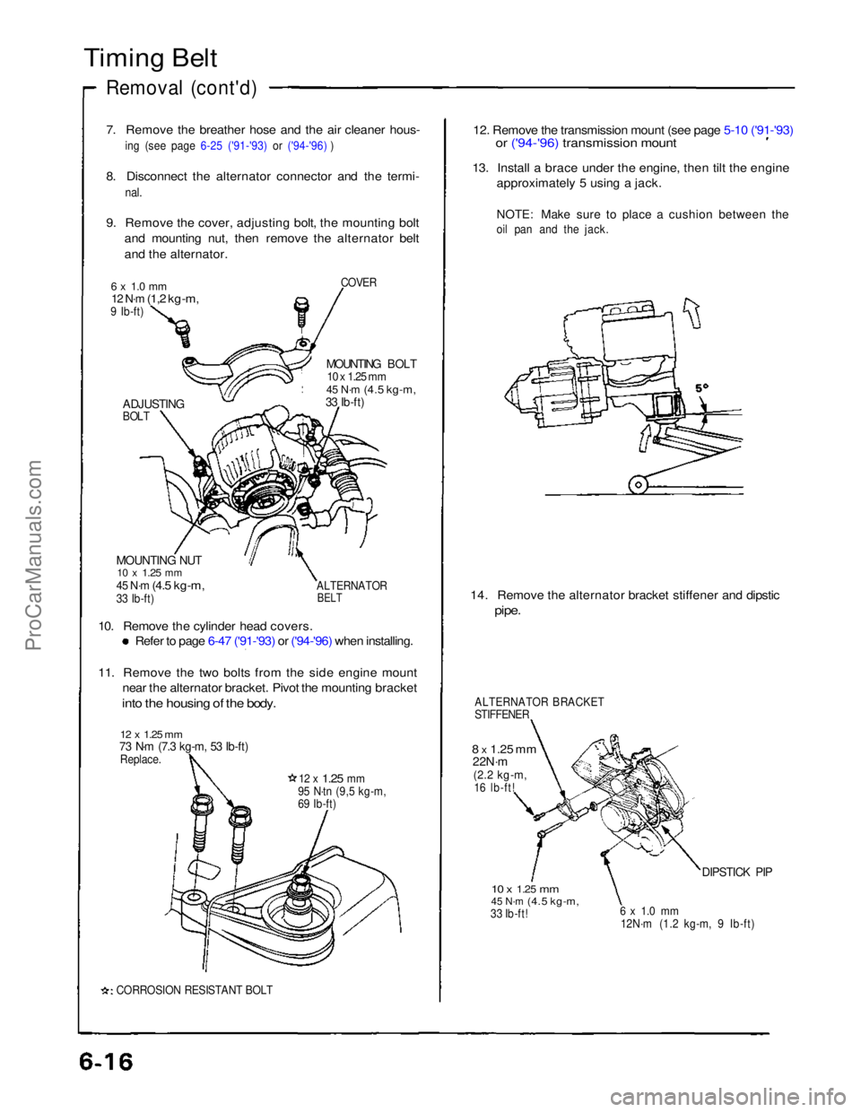
Timing Belt
Removal (cont'd)
7. Remove the breather hose and the air cleaner hous-
in
g
(see page 6-25 ('91-'93) or ('94-'96) )
8. Disconnect the alternator connector and the termi-
nal.
9. Remove the cover, adjusting bolt, the mounting bolt and mounting nut, then remove the alternator belt
and the alternator.
COVER
6 x 1.0 mm
12 N·m
(1,2 kg-m,
9 Ib-ft)
MOUNTING BOLT
10 x 1.25 mm
45 N·m
(4.5 kg-m,
33 Ib-ft)
ADJUSTING
BOLT
MOUNTING NUT
10 x
1.25
mm
45 N·m
(4.5 kg-m,
33 Ib-ft)
ALTERNATOR
BELT
10. Remove the cylinder head covers.
Refer to page 6-47 ('91-'93) or ('94-'96) when installing.
11. Remove the two bolts from the side engine mount
near the alternator bracket. Pivot the mounting bracket
into the housing of the body.
12 x 1.25 mm
73 N·m (7.3 kg-m, 53 Ib-ft)
Replace.
12 x
1.25
mm
95 N·tn (9,5 kg-m,
69 Ib-ft)
CORROSION RESISTANT BOLT
12. Remove the transmission mount (see page 5-10 ('91-'93)
or ('94-'96) transmission mount
13. Install a brace under the engine, then tilt the engine
approximately 5 using a jack.
NOTE: Make sure to place a cushion between the
oil pan and the jack.
14. Remove the alternator bracket stiffener and dipstic
pipe.
ALTERNATOR BRACKET
STIFFENER
8 x
1.25
mm
22N·m
(2.2 kg-m,
16 lb-ft!
10 x
1.25
mm
45 N·m
(4.5 kg-m,
33 Ib-ft!
6 x 1.0 mm
12N·m (1.2 kg-m, 9 Ib-ft)
DIPSTICK PIPProCarManuals.com
Page 97 of 1640
![ACURA NSX 1991 Service Repair Manual
Cylinder Heads
Illustrated Index (cont'd)
CAUTION:
To
avoid
damage,
wait
until
the
engine
coolant
temperature
drops
below
100°F
(39-C]
before
removing
the
cylin-
der head.
N](/manual-img/32/56988/w960_56988-96.png "ACURA NSX 1991 Service Repair Manual
Cylinder Heads
Illustrated Index (cont'd)
CAUTION:
To
avoid
damage,
wait
until
the
engine
coolant
temperature
drops
below
100°F
(39-C]
before
removing
the
cylin-
der head.
N")
Cylinder Heads
Illustrated Index (cont'd)
CAUTION:
To
avoid
damage,
wait
until
the
engine
coolant
temperature
drops
below
100°F
(39-C]
before
removing
the
cylin-
der head.
NOTE: Use new O-rings and gaskets when reassembling.
Prior to reassembling, clean all the parts in solvent, dry them, and apply lubricant to any contact parts.
REAR VARIABLE VALVE TIMING
AND VALVE LIFT ELECTRONIC CONTROL
SYSTEM (VTEC) SOLENOID VALVE
Troubleshooting, page 6-3 ('91-'93) or ('94-'96)
EXHAUST GAS
RECIRCULATI0N (EGR) VALVE
6 x 1 .0 mm
12 N·m
(1.2 kg-m.
9 Ib-ft)
8 x
1.25
mm
22 N·m
(2.2 kg-m,
16 Ib-ft)
ENGINE COOLANT
TEMPERATURE (ECT) SENSOR
18 N·m (1.8 kg-m, 13 Ib-ft)
8 x
1.25
mm
22 N·m (2.2 kg-m. 16 lb-ft)
FRONT VTEC SOLENOID VALVE
Troubleshooting. page 6-3
SEALING BOLTS
60 N·m
(6.0 kg-m,
43 lb-ft)
OIL PRESSURE
GAUSE SENDING
UNIT (section 23)
ROCKER
SHAFTS
WASHERS
Replace.
8 x
1.25
mm
22 N·m
(2.2 kg-m,16 Ib-ft)
DOWEL PIN
0-RING
Replace.
ECT SWITCH
28 N·m
12.8 kg-m.
20 lb-ft
O-RING
Replace.
O-RING
Replace.
ROCKER ARM ASSEMBLY[PRIMARY. MID, SECONDARY]
Inspection, page 6-32 ('91-'93) or ('94-'96)
ROCKER SHAFT
OIL CONTROL
ORIFICE
Remove with 5 mm
boit and clean.
FILTER
Replace.
GASKET
Replace.
O-RING
Replace.ProCarManuals.com
Page 99 of 1640
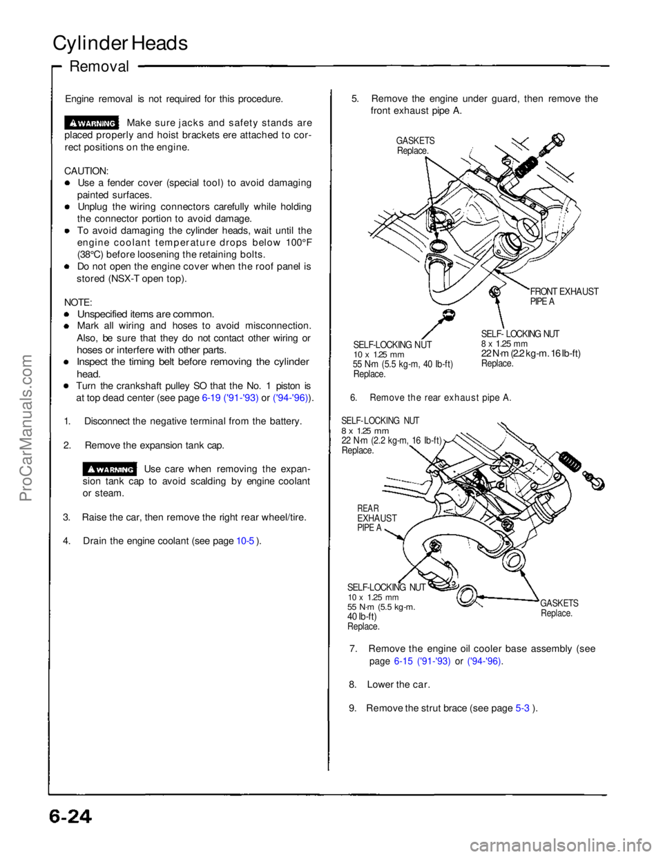
Cylinder Heads
Removal
Engine removal is not required for this procedure. Make sure jacks and safety stands are
placed properly and hoist brackets ere attached to cor- rect positions on the engine.
CAUTION: Use a fender cover (special tool) to avoid damaging
painted surfaces. Unplug the wiring connectors carefully while holding
the connector portion to avoid damage.
To avoid damaging the cylinder heads, wait until the
engine coolant temperature drops below 100°F
(38°C) before loosening the retaining bolts. Do not open the engine cover when the roof panel is
stored (NSX-T open top).
NOTE:
Unspecified items are common.
Mark all wiring and hoses to avoid misconnection.
Also, be sure that they do not contact other wiring or
hoses or interfere with other parts.
Inspect the timing belt before removing the cylinder
head.
Turn the crankshaft pulley SO that the No. 1 piston is at top dead center (see page 6-19 ('91-'93) or ('94-'96)).
1. Disconnect the negative terminal from the battery.
2. Remove the expansion tank cap. Use care when removing the expan-
sion tank cap to avoid scalding by engine coolant
or steam.
3. Raise the car, then remove the right rear wheel/tire.
4. Drain the engine coolant (see page 10-5 ). 5. Remove the engine under guard, then remove the
front exhaust pipe A.
GASKETS
Replace.
FRONT EXHAUST
PIPE A
SELF-LOCKING NUT
10 x
1.25
mm
55 N·m (5.5 kg-m, 40 Ib-ft)
Replace.
SELF- LOCKING NUT
8 x
1.25
mm
22 N·m (2.2 kg-m. 16 Ib-ft)
Replace.
6. Remove the rear exhaust pipe A.
SELF- LOCKING NUT
8 x
1.25
mm
22 N·m (2.2 kg-m, 16 Ib-ft)
Replace.
REAR
EXHAUST
PIPE A
SELF-LOCKING NUT
10 x
1.25
mm
55 N·m (5.5 kg-m.
40 Ib-ft)
Replace.
GASKETS
Replace.
7. Remove the engine oil cooler base assembly (see
page 6-15 ('91-'93) or ('94-'96).
8. Lower the car.
9. Remove the strut brace (see page 5-3 ).ProCarManuals.com