Page 437 of 1640

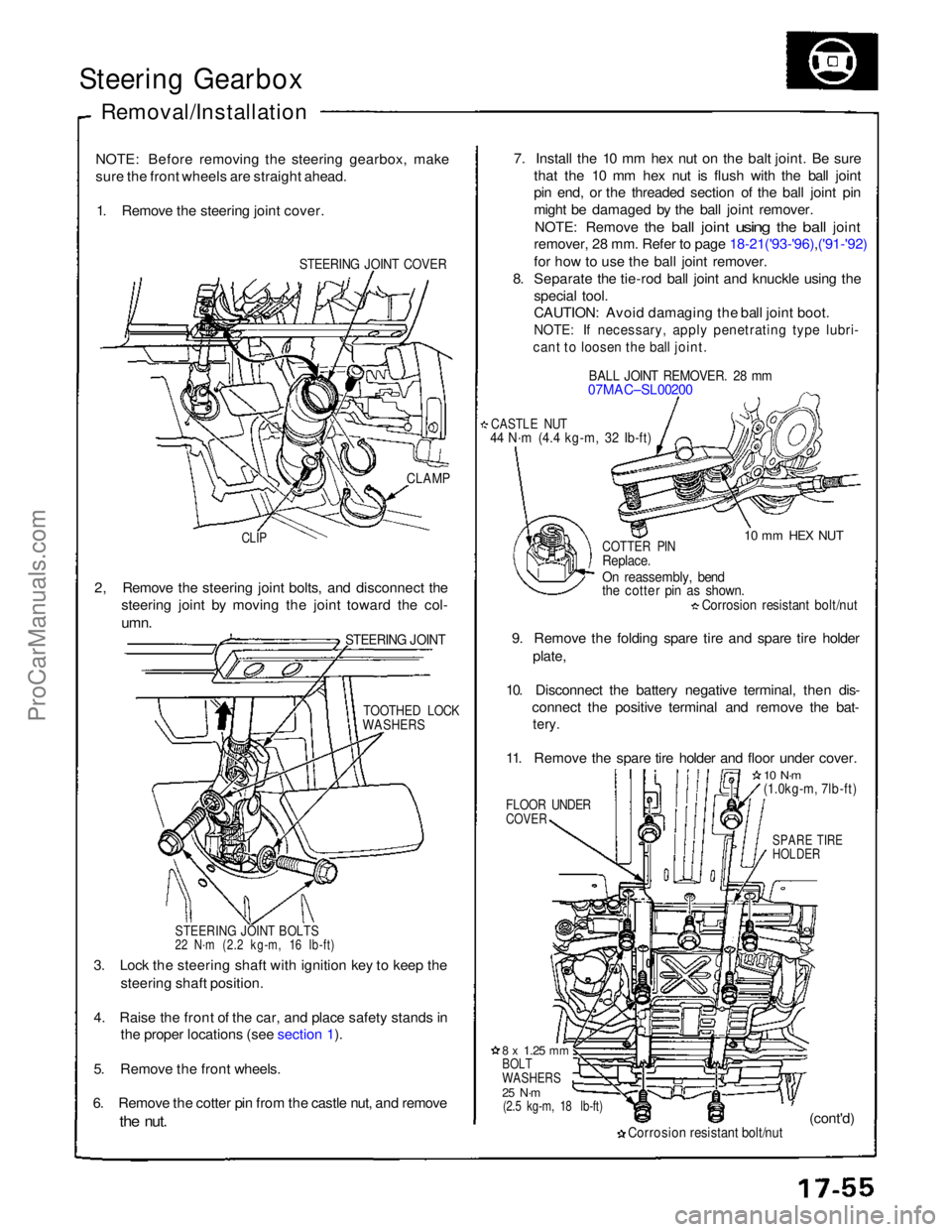
Steering Gearbox
Removal/Installation
NOTE: Before removing the steering gearbox, make
sure the front wheels are straight ahead. 1. Remove the steering joint cover.
STEERING JOINT COVER
7. Install the 10 mm hex nut on the balt joint. Be sure
that the 10 mm hex nut is flush with the ball joint
pin end, or the threaded section of the ball joint pin
might be damaged by the ball joint remover.
NOTE: Remove
the
ball
joint
using
the
ball
joint
remover, 28 mm. Refer to page 18-21('93-'96),('91-'92)
for how to use the ball joint remover.
8. Separate the tie-rod ball joint and knuckle using the
special tool.
CAUTION: Avoid damaging the ball joint boot.
NOTE: If necessary, apply penetrating type lubri-
cant to loosen the ball joint.
BALL JOINT REMOVER. 28 mm
07MAC–SL00200
CASTLE NUT
44 N·m (4.4 kg-m, 32 Ib-ft)
10 mm HEX NUT
CLAMP
CLIP
COTTER PIN
Replace.
On reassembly, bend
the cotter pin as shown.
Corrosion resistant bolt/nut
9. Remove the folding spare tire and spare tire holder plate,
10. Disconnect the battery negative terminal, then dis- connect the positive terminal and remove the bat-
tery.
11. Remove the spare tire holder and floor under cover.
FLOOR UNDER
COVER
10 N·m
(1.0kg-m, 7lb-ft)
SPARE TIRE
HOLDER
2, Remove the steering joint bolts, and disconnect the
steering joint by moving the joint toward the col-
umn.
STEERING JOINT
TOOTHED LOCK
WASHERS
STEERING JOINT BOLTS
22 N·m (2.2 kg-m, 16 Ib-ft)
3. Lock the steering shaft with ignition key to keep the steering shaft position.
4. Raise the front of the car, and place safety stands in the proper locations (see section 1).
5. Remove the front wheels.
6. Remove the cotter pin from the castle nut, and remove
the
nut.
8 x
1.25
mm
BOLT
WASHERS
25 N·m
(2.5 kg-m, 18 lb-ft)
Corrosion resistant bolt/nut
(cont'd)ProCarManuals.com
Page 1312 of 1640

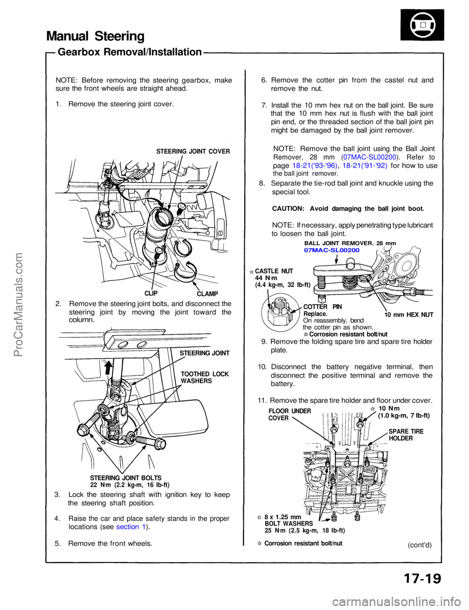
Manual Steering
Gearbox Removal/Installation
NOTE: Before removing the steering gearbox, make
sure the front wheels are straight ahead.
1. Remove the steering joint cover.
STEERING JOINT COVER
CLAMP
CLIP
2. Remove the steering joint bolts, and disconnect the steering joint by moving the joint toward the
column.
STEERING JOINT
STEERING JOINT BOLTS
22 N .
m (2.2 kg-m, 16 Ib-ft)
3. Lock the steering shaft with ignition key to keep the steering shaft position.
4. Raise the car and place safety stands in the proper
locations (see section 1).
5. Remove the front wheels.
8 x
1.25
mm
BOLT WASHERS
25 N .
m (2.5 kg-m, 18 Ib-ft)
Corrosion resistant bolt/nut
FLOOR UNDER
COVER
9. Remove the folding spare tire and spare tire holder
plate.
10. Disconnect the battery negative terminal, then disconnect the positive terminal and remove the
battery.
11. Remove the spare tire holder and floor under cover.
10 N·
m
(1.0 kg-m, 7 Ib-ft)
SPARE TIRE
HOLDER
(cont'd)
COTTER PIN
Replace.
On reassembly, bend
the cotter pin as shown.
Corrosion resistant bolt/nut
CASTLE NUT
44 N
·
m
(4.4 kg-m, 32 Ib-ft)
10 mm HEX NUT
NOTE: If necessary, apply penetrating type lubricant
to loosen the ball joint.
BALL JOINT REMOVER. 28 mm
07MAC-SL00200
6. Remove the cotter pin from the castel nut and
remove the nut.
7. Install the 10 mm hex nut on the ball joint. Be sure that the 10 mm hex nut is flush with the ball joint
pin end, or the threaded section of the ball joint pin
might be damaged by the ball joint remover.
NOTE: Remove the ball joint using the Ball Joint
Remover, 28 mm (07MAC-SL00200). Refer to
page 18-21('93-'96), 18-21('91-'92) for how to use
8. Separate the tie-rod ball joint and knuckle using the special tool.
CAUTION: Avoid damaging the ball joint boot.
TOOTHED LOCK
WASHERSProCarManuals.com
Page 1340 of 1640

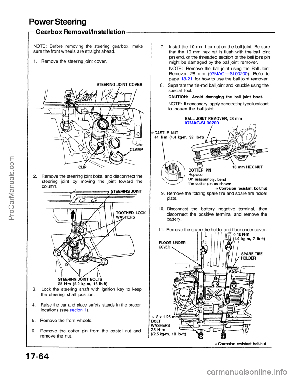
Power Steering
Gearbox Removal/Installation
NOTE: Before removing the steering gearbox, make
sure the front wheels are straight ahead.
1. Remove the steering joint cover.
STEERING JOINT COVER
CLAMP
CLIP
2. Remove the steering joint bolts, and disconnect the steering joint by moving the joint toward the
STEERING JOINT
column.
STEERING JOINT BOLTS
22 N.
m (2.2 kg-m, 16 Ib-ft)
3. Lock the steering shaft with ignition key to keep the steering shaft position.
4. Raise the car and place safety stands in the proper
locations (see secion 1).
5. Remove the front wheels.
6. Remove the cotter pin from the castel nut and remove the nut. 7. Install the 10 mm hex nut on the ball joint. Be sure
that the 10 mm hex nut is flush with the ball joint
pin end, or the threaded section of the ball joint pin
might be damaged by the ball joint remover.
NOTE: Remove the ball joint using the Ball Joint
Remover, 28 mm (07MAC —SL00200). Refer to
page 18-21 for how to use the ball joint remover.
8. Separate the tie-rod ball joint and knuckle using the special tool.
CAUTION: Avoid damaging the ball joint boot.
NOTE: If necessary, apply penetrating type lubricant
to loosen the ball joint.
BALL JOINT REMOVER, 28 mm
07MAC-SL00200
CASTLE NUT
44 N .
m (4.4 kg-m, 32 Ib-ft)
COTTER PIN
Replace.
10 mm HEX NUT
Corrosion resistant bolt/nut
9. Remove the folding spare tire and spare tire holder plate.
10. Disconnect the battery negative terminal, then disconnect the positive terminal and remove the
battery.
11. Remove the spare tire holder and floor under cover.
10 N·m
SPARE TIRE
HOLDER
FLOOR UNDER
COVER
8 x
1.25
mm
BOLT
WASHERS
25 N .
m
(2.5 kg-m, 18 Ib-ft)
Corrosion resistant bolt/nut
TOOTHED LOCK
WASHERS
(1.0 kg-m, 7 Ib-ft)ProCarManuals.com