Page 45 of 1640
Service Precaution s
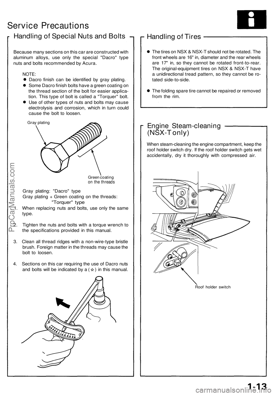
Handling o f Specia l Nut s an d Bolt s
Becaus e man y section s o n thi s ca r ar e constructe d wit h
aluminu m alloys , us e onl y th e specia l "Dacro " typ e
nut s an d bolt s recommende d b y Acura .
NOTE:
Dacro finis h ca n b e identifie d b y gra y plating .
Som e Dacr o finis h bolt s hav e a gree n coatin g o n
th e threa d sectio n of the bol t fo r easie r applica -
tion . Thi s typ e of bol t i s calle d a "Torquer " bolt .
Us e o f othe r type s of nut s an d bolt s ma y caus e
electrolysi s an d corrosion , whic h in tur n coul d
caus e th e bol t t o loosen .
Gray platin g
Green coatin g
on th e thread s
Gray plating : "Dacro " typ e
Gra y platin g + Gree n coatin g o n th e threads :
"Torquer " typ e
1. Whe n replacin g nut s an d bolts , us e onl y th e sam e
type.
2. Tighte n th e nut s an d bolt s with a torqu e wrenc h t o
th e specification s provide d i n thi s manual .
3 . Clea n al l threa d ridge s wit h a non-wire-typ e bristl e
brush . Foreig n matte r i n th e thread s ma y caus e th e
bol t t o loosen .
4 . Section s o n thi s ca r requirin g th e us e o f Dacr o nut s
and bolt s wil l b e indicate d b y a ( ) in thi s manual .
Handling o f Tire s
The tire s o n NS X & NSX- T shoul d no t b e rotated . Th e
fron t wheel s ar e 16 " in , diamete r an d th e rea r wheel s
ar e 17 " in , s o the y canno t b e rotate d front-to-rear .
Th e original-equipmen t tire s o n NS X & NSX- T hav e
a unidirectiona l trea d pattern , s o the y canno t b e ro -
tate d side-to-side .
Th e foldin g spar e tir e canno t b e repaire d o r remove d
fro m th e rim .
Engin e Steam-cleanin g
(NSX-T only )
When steam-cleanin g th e engin e compartment , kee p th e
roo f holde r switc h dry . I f th e roo f holde r switc h get s we t
accidentally , dr y i t thoroughl y wit h compresse d air .
Roo f holde r switc h
ProCarManuals.com
Page 156 of 1640
28. Tighten bolts and nuts finger tight at six points as
shown below.
29. Starting with nut torque all bolts and nuts, in a
clockwise pattern in three steps.
NOTE: Excessive tightening can cause distortion of
oil pan gasket and oil leakage.
Torque: 14 N-m (1.4 kg-m, 10 lb-ft)ProCarManuals.com
Page 299 of 1640
6. Install the release bearing on the pressure plate.
7. Install the pressure plate.
NOTE:
Align the mark on the mid plate with the mark onthe pressure plate.
After installing, make sure the release bearing is
secure.
Align the marks.
PRESSURE PLATE
RELEASE BEARING
PRESSURE PLATE
(P/N 08798-9002)
RELEASE
BEARING
Place the diaphragm spring fingers
in the groove of the release bearing.
9. Remove the special tools.
10. Initialize the mid plate guides (see page 12-14
('93-'96), 12-16 ('91-'92 Models).
MOUNTING BOLT
8 x
1.25
mm
22 N·m (2.2 kg-m, 16 Ib-ft)
8. Torque the mounting bolts in a crisscross pattern
as shown. Tighten them several steps to prevent
warping the diaphragm spring.
NOTE: Place the diaphragm spring fingers in the
groove of the release bearing.ProCarManuals.com
Page 310 of 1640
Transmission Housing
Removal
NOTE: Place the clutch housing on two pieces of wood
thick enough to keep the mainshaft from hitting the
workbench.
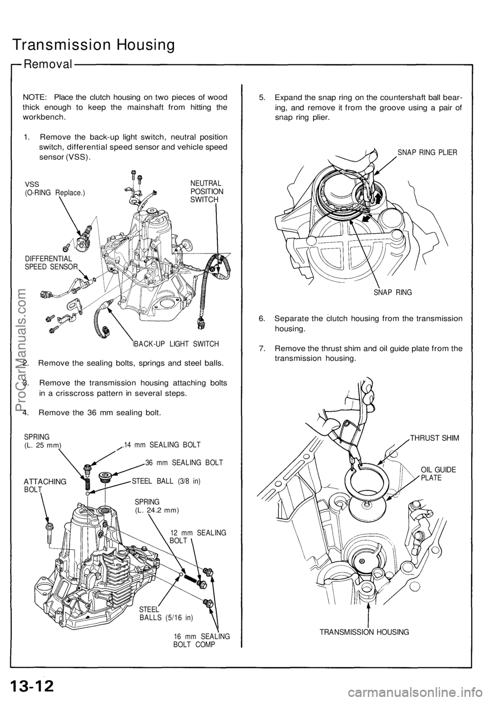
1. Remove the back-up light switch, neutral position
switch, differential speed sensor and vehicle speed
sensor (VSS).
VSS
(O-RING Replace.)
NEUTRAL
POSITION
SWITCH
DIFFERENTIAL
SPEED SENSOR
BACK-UP LIGHT SWITCH
2. Remove the sealing bolts, springs and steel balls.
3. Remove the transmission housing attaching bolts
in a crisscross pattern in several steps.
4. Remove the 36 mm sealing bolt.
SPRING
(L. 25 mm)
ATTACHING
BOLT
.14 mm SEALING BOLT
36 mm SEALING BOLT
STEEL BALL (3/8 in)
12 mm SEALING
BOLT
16 mm SEALING
BOLT COMP
5. Expand the snap ring on the countershaft ball bear-
ing, and remove it from the groove using a pair of
snap ring plier.
SNAP RING PLIER
SNAP RING
6. Separate the clutch housing from the transmission
housing.
7. Remove the thrust shim and oil guide plate from the
transmission housing.
THRUST SHIM
OIL GUIDE
PLATE
TRANSMISSION HOUSING
SPRING
(L.
24.2
mm)
STEEL
BALLS (5/16 in)ProCarManuals.com
Page 367 of 1640
I
Oil Seal
Removal
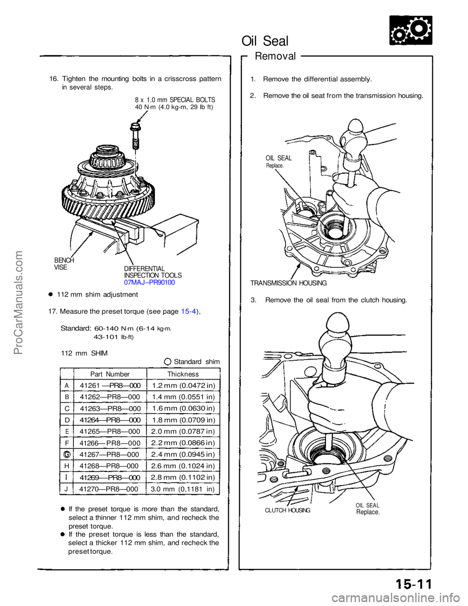
16. Tighten the mounting bolts in a crisscross pattern
in several steps.
8 x 1.0 mm SPECIAL BOLTS
40 N·m
(4.0 kg-m,
29 Ib ft)
1. Remove the differential assembly.
2. Remove the oil seat from the transmission housing.
OIL SEAL
Replace.
DIFFERENTIAL
INSPECTION TOOLS
07MAJ–PR90100
BENCH
VISE
TRANSMISSION HOUSING
112 mm shim adjustment
17. Measure the preset torque (see page 15-4),
Standard:
60-140
N·m
(6-14
kg-m.
43-101
Ib-ft)
112 mm SHIM Standard shim3. Remove the oil seal from the clutch housing.
A
B
C
D
E
F
H
J
Part Number
41261
—PR8—000
41262—PR8—000
41263—PR8—000
41264—PR8—-000
41265—PR8—000
41266— PR8—000
41267—PR8—000
41268—PR8—000
41269—-PR8—000
41270—PR8—000
Thickness
1.2 mm (0.0472 in)
1.4 mm (0.0551 in)
1.6 mm (0.0630 in)
1.8 mm (0.0709 in)
2.0 mm (0.0787 in)
2.2 mm (0.0866 in)
2.4 mm (0.0945 in)
2.6 mm (0.1024 in)
2.8 mm (0.1102 in)
3.0 mm (0,1181 in)
If the preset torque is more than the standard,
select a thinner 112 mm shim, and recheck the
preset torque.
If the preset torque is less than the standard,
select a thicker 112 mm shim, and recheck the
preset torque.
CLUTCH HOUSING
OIL SEAL
Replace.
ProCarManuals.com
Page 377 of 1640
\
I
Clutch Disc, Clutch Plate
Replacement
NOTE: The clutch discs and clutch plates should be
replaced as a set.
1. Remove the clutch discs and clutch plates (see
page15-20).
2. Soak the clutch discs for five minutes in transmis-
sion oil.
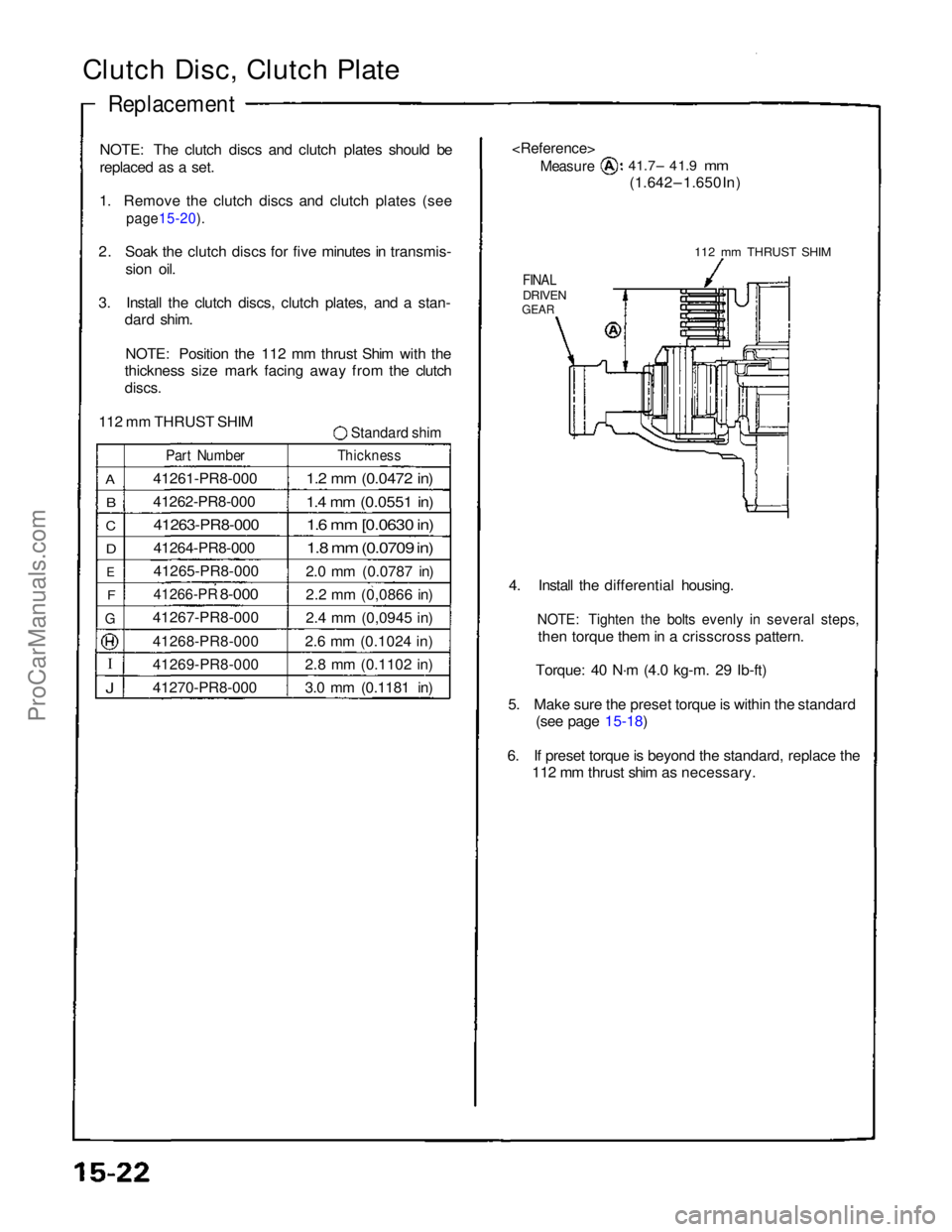
3. Install the clutch discs, clutch plates, and a stan- dard shim.
NOTE: Position the 112 mm thrust Shim with the
thickness size mark facing away from the clutch
discs.
112 mm THRUST SHIM
Standard shim
A
B
C
D
E
F
G
J
Part Number
41261-PR8-000
41262-PR8-000
41263-PR8-000
41264-PR8-000
41265-PR8-000
41266-PR
8-000
41267-PR8-000
41268-PR8-000
41269-PR8-000
41270-PR8-000
Thickness
1.2 mm (0.0472 in)
1.4 mm (0.0551 in)
1.6 mm [0.0630 in)
1.8 mm (0.0709 in)
2.0 mm (0.0787 in)
2.2 mm (0,0866 in)
2.4 mm (0,0945 in)
2.6 mm (0.1024 in)
2.8 mm (0.1102 in)
3.0 mm (0.1181 in)
Measure
41.7– 41.9
mm
(1.642 – 1.650 In)
112 mm THRUST SHIM
FINAL
DRIVEN
GEAR
4. Install the differential housing.
NOTE: Tighten the bolts evenly in several steps,
then torque them in a crisscross pattern.
Torque: 40 N·m (4.0 kg-m. 29 Ib-ft)
5. Make sure the preset torque is within the standard (see page 15-18)
6. If preset torque is beyond the standard, replace the 112 mm thrust shim as necessary.ProCarManuals.com
Page 1154 of 1640
SEALING
BOLT
STEEL
BALLS (5/16 in)
Transmission Housing
Removal
NOTE: Place the clutch housing on two pieces of wood
thick enough to keep the mainshaft from hitting the
workbench.
1. Remove the back-up light switch, neutral position
switch and vehicle speed sensor (VSS).
NEUTRAL
POSITION
SWITCH
VSS
(O-RING Replace .)
BACK-UP LIGHT SWITCH36 mm SEALING BOLT
SPRING
(L. 25 mm)
ATTACHING BOLTS
2. Remove the sealing bolts, springs and steel balls.
3. Remove the transmission housing attaching bolts in a criss-cross pattern in several steps.
4. Remove the 36 mm sealing bolt.
STEEL BALL (3/8 in)
SPRING
(L.
25.1
mm)
SPRING
(L. 30 mm)
TRANSMISSION HOUSINGTHRUST SHIM
OIL GUIDE
PLATE
6. Separate the clutch housing from the transmission
housing. SNAP RINGSNAP RING PLIER
5. Expand the snap ring on the countershaft ball bear-
ing and remove it from the groove using a pair of
snap ring plier.
7. Remove the thrust shim and oil guide plate from the transmission housing.ProCarManuals.com
Page 1159 of 1640
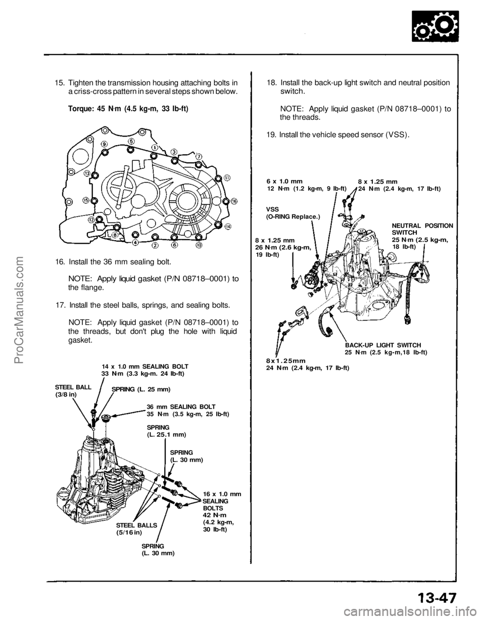
15. Tighten the transmission housing attaching bolts in
a criss-cross pattern in several steps shown below.
Torque: 45 N .
m (4.5 kg-m, 33 Ib-ft)
16. Install the 36 mm sealing bolt.
NOTE: Apply liquid gasket (P/N 08718–0001) to
the flange.
17. Install the steel balls, springs, and sealing bolts. NOTE: Apply liquid gasket (P/N 08718–0001) to
the threads, but don't plug the hole with liquid
gasket.
14 x 1.0 mm SEALING BOLT
33 N .
m (3.3 kg-m. 24 Ib-ft)
STEEL BALL
(3/8
in)
SPRING (L. 25 mm)
36 mm SEALING BOLT
35 N.
m (3.5 kg-m, 25 Ib-ft)
SPRING
(L.
25.1
mm)
SPRING
(L. 30 mm)
16 x 1.0 mm
SEALING BOLTS
42 N .
m
(4.2 kg-m,
30 Ib-ft)
STEEL BALLS
(5/16
in)
SPRING
(L. 30 mm)
18. Install the back-up light switch and neutral position
switch.
NOTE: Apply liquid gasket (P/N 08718–0001) to
the threads.
19. Install the vehicle speed sensor (VSS).
6 x 1.0 mm
12 N .
m (1.2 kg-m, 9 Ib-ft)
VSS
(O-RING Replace.)
8 x
1.25
mm
24 N .
m (2.4 kg-m, 17 Ib-ft)
NEUTRAL POSITION
SWITCH
25 N.
m
(2.5 kg-m,
18 Ib-ft)
BACK-UP LIGHT SWITCH
25 N .
m (2.5 kg-m,18 Ib-ft)
8x1.25 mm
24 N .
m (2.4 kg-m, 17 Ib-ft)
8 x
1.25
mm
26 N
.
m
(2.6 kg-m,
19 Ib-ft)ProCarManuals.com