1991 ACURA NSX wheel bolts
[x] Cancel search: wheel boltsPage 45 of 1640
Service Precaution s
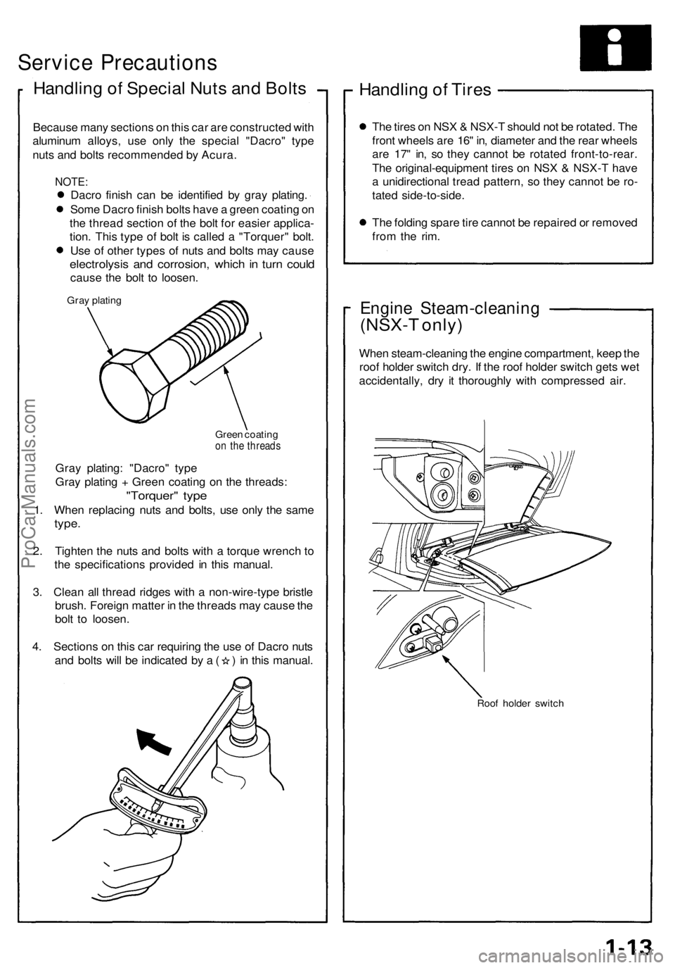
Handling o f Specia l Nut s an d Bolt s
Becaus e man y section s o n thi s ca r ar e constructe d wit h
aluminu m alloys , us e onl y th e specia l "Dacro " typ e
nut s an d bolt s recommende d b y Acura .
NOTE:
Dacro finis h ca n b e identifie d b y gra y plating .
Som e Dacr o finis h bolt s hav e a gree n coatin g o n
th e threa d sectio n of the bol t fo r easie r applica -
tion . Thi s typ e of bol t i s calle d a "Torquer " bolt .
Us e o f othe r type s of nut s an d bolt s ma y caus e
electrolysi s an d corrosion , whic h in tur n coul d
caus e th e bol t t o loosen .
Gray platin g
Green coatin g
on th e thread s
Gray plating : "Dacro " typ e
Gra y platin g + Gree n coatin g o n th e threads :
"Torquer " typ e
1. Whe n replacin g nut s an d bolts , us e onl y th e sam e
type.
2. Tighte n th e nut s an d bolt s with a torqu e wrenc h t o
th e specification s provide d i n thi s manual .
3 . Clea n al l threa d ridge s wit h a non-wire-typ e bristl e
brush . Foreig n matte r i n th e thread s ma y caus e th e
bol t t o loosen .
4 . Section s o n thi s ca r requirin g th e us e o f Dacr o nut s
and bolt s wil l b e indicate d b y a ( ) in thi s manual .
Handling o f Tire s
The tire s o n NS X & NSX- T shoul d no t b e rotated . Th e
fron t wheel s ar e 16 " in , diamete r an d th e rea r wheel s
ar e 17 " in , s o the y canno t b e rotate d front-to-rear .
Th e original-equipmen t tire s o n NS X & NSX- T hav e
a unidirectiona l trea d pattern , s o the y canno t b e ro -
tate d side-to-side .
Th e foldin g spar e tir e canno t b e repaire d o r remove d
fro m th e rim .
Engin e Steam-cleanin g
(NSX-T only )
When steam-cleanin g th e engin e compartment , kee p th e
roo f holde r switc h dry . I f th e roo f holde r switc h get s we t
accidentally , dr y i t thoroughl y wit h compresse d air .
Roo f holde r switc h
ProCarManuals.com
Page 80 of 1640
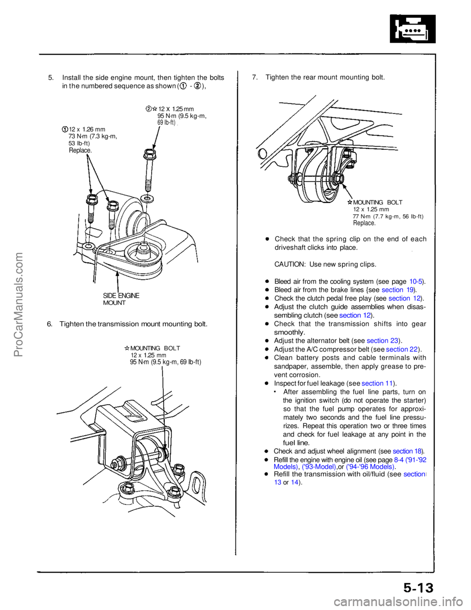
5. Install the side engine mount, then tighten the bolts
in the numbered sequence as shown ( - ),
12 x
1.26
mm
73 N·m
(7.3 kg-m,
53 Ib-ft)
Replace.
12 x
1.25
mm
95 N·m
(9.5 kg-m,
69 Ib-ft)
SIDE ENGINE
MOUNT
6. Tighten the transmission mount mounting bolt.
MOUNTING BOLT
12 x
1.25
mm
95 N·m (9.5 kg-m, 69 Ib-ft)
7. Tighten the rear mount mounting bolt.
MOUNTING BOLT
12 x
1.25
mm
77 N·m (7.7 kg-m, 56 Ib-ft)
Replace.
Check that the spring clip on the end of each
driveshaft clicks into place.
CAUTION: Use new spring clips.
Bleed air from the cooling system (see page 10-5).
Bleed air from the brake lines {see section 19).
Check the clutch pedal free play (see section 12).
Adjust the clutch guide assemblies when disas-
sembling clutch (see section 12).
Check that the transmission shifts into gear
smoothly.
Adjust the alternator belt (see section 23).
Adjust the A/C compressor belt (see section 22).
Clean battery posts and cable terminals with
sandpaper, assemble, then apply grease to pre-
vent corrosion.
Inspect for fuel leakage (see section 11). After assembling the fuel line parts, turn on
the ignition switch (do not operate the starter) so that the fuel pump operates for approxi-
mately two seconds and the fuel line pressu-
rizes. Repeat this operation two or three times
and check for fuel leakage at any point in the
fuel line.
Check and adjust wheel alignment (see section 18).
Refill the engine with engine oil (see page 8-4 ('91-'92
Models), ('93-Model),or ('94-'96 Models).
Refill the transmission with oil/fluid (see section
13 or
14).ProCarManuals.com
Page 99 of 1640
Cylinder Heads
Removal
Engine removal is not required for this procedure. Make sure jacks and safety stands are
placed properly and hoist brackets ere attached to cor- rect positions on the engine.
CAUTION: Use a fender cover (special tool) to avoid damaging
painted surfaces. Unplug the wiring connectors carefully while holding
the connector portion to avoid damage.
To avoid damaging the cylinder heads, wait until the
engine coolant temperature drops below 100°F
(38°C) before loosening the retaining bolts. Do not open the engine cover when the roof panel is
stored (NSX-T open top).
NOTE:
Unspecified items are common.
Mark all wiring and hoses to avoid misconnection.
Also, be sure that they do not contact other wiring or
hoses or interfere with other parts.
Inspect the timing belt before removing the cylinder
head.
Turn the crankshaft pulley SO that the No. 1 piston is at top dead center (see page 6-19 ('91-'93) or ('94-'96)).
1. Disconnect the negative terminal from the battery.
2. Remove the expansion tank cap. Use care when removing the expan-
sion tank cap to avoid scalding by engine coolant
or steam.
3. Raise the car, then remove the right rear wheel/tire.
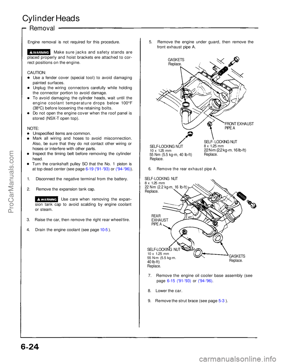
4. Drain the engine coolant (see page 10-5 ). 5. Remove the engine under guard, then remove the
front exhaust pipe A.
GASKETS
Replace.
FRONT EXHAUST
PIPE A
SELF-LOCKING NUT
10 x
1.25
mm
55 N·m (5.5 kg-m, 40 Ib-ft)
Replace.
SELF- LOCKING NUT
8 x
1.25
mm
22 N·m (2.2 kg-m. 16 Ib-ft)
Replace.
6. Remove the rear exhaust pipe A.
SELF- LOCKING NUT
8 x
1.25
mm
22 N·m (2.2 kg-m, 16 Ib-ft)
Replace.
REAR
EXHAUST
PIPE A
SELF-LOCKING NUT
10 x
1.25
mm
55 N·m (5.5 kg-m.
40 Ib-ft)
Replace.
GASKETS
Replace.
7. Remove the engine oil cooler base assembly (see
page 6-15 ('91-'93) or ('94-'96).
8. Lower the car.
9. Remove the strut brace (see page 5-3 ).ProCarManuals.com
Page 130 of 1640
Flywheel an d Driv e Plat e
Replacemen t
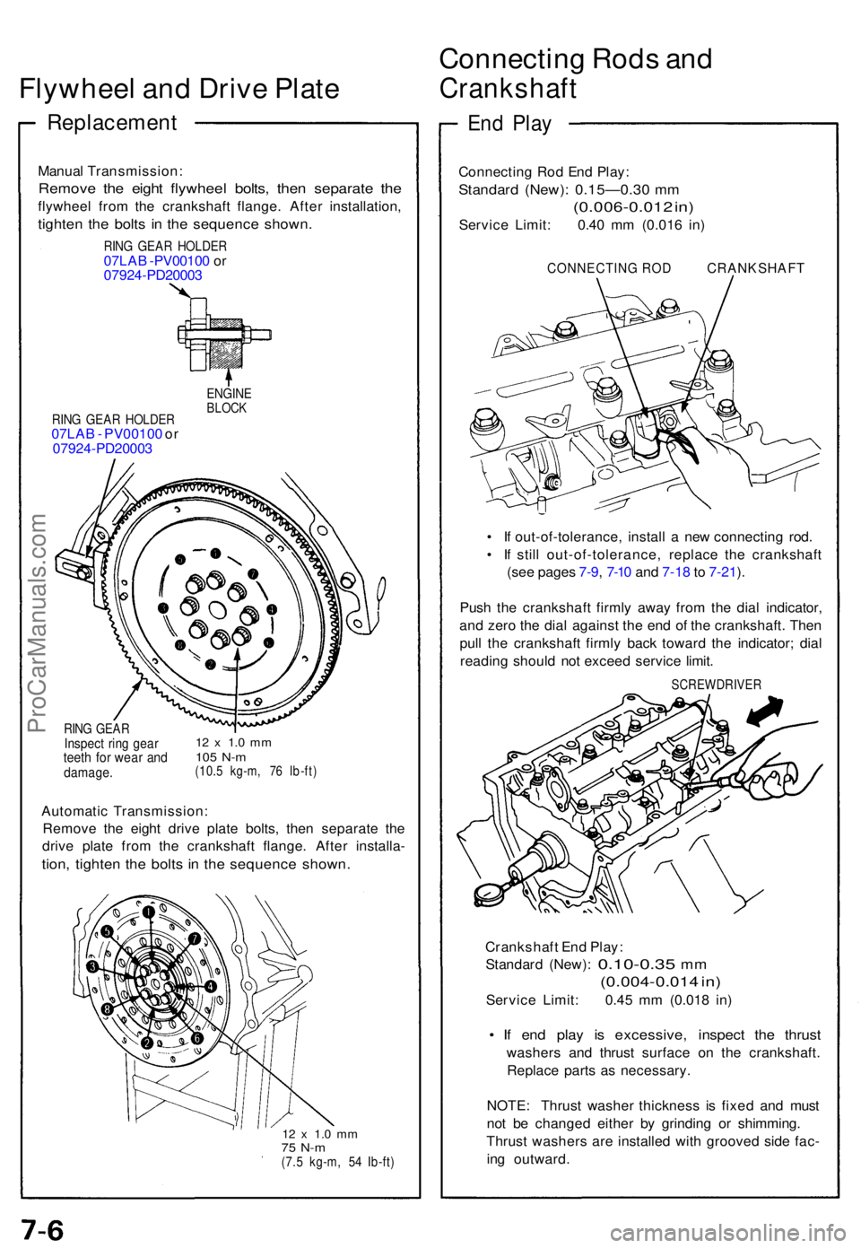
Manual Transmission :
Remove th e eigh t flywhee l bolts , the n separat e th e
flywhee l fro m th e crankshaf t flange . Afte r installation ,
tighten th e bolt s i n th e sequenc e shown .
RING GEA R HOLDE R07LAB -PV0010 0 o r
0792 4-PD2000 3
RING GEA R HOLDE R07LAB - PV00100 or
0792 4-PD2000 3
ENGINEBLOCK
RING GEA RInspec t rin g gea rteeth fo r wea r an ddamage .
12 x 1. 0 m m105 N- m(10. 5 kg-m , 7 6 Ib-ft )
Automati c Transmission :
Remov e th e eigh t driv e plat e bolts , the n separat e th e
driv e plat e fro m th e crankshaf t flange . Afte r installa -
tion, tighte n th e bolt s i n th e sequenc e shown .
12 x 1. 0 m m75 N- m(7.5 kg-m , 5 4 Ib-ft )
Connectin g Rod s an d
Crankshaf t
End Pla y
Connectin g Ro d En d Play :
Standar d (New) : 0.15—0.3 0 m m
(0.006-0.01 2 in )
Servic e Limit : 0.4 0 m m (0.01 6 in )
CONNECTIN G RO D CRANKSHAF T
• I f out-of-tolerance , instal l a ne w connectin g rod .
• I f stil l out-of-tolerance , replac e th e crankshaf t
(se e page s 7-9 , 7-1 0 an d 7-1 8 to 7-21 ).
Pus h th e crankshaf t firml y awa y fro m th e dia l indicator ,
an d zer o th e dia l agains t th e en d o f th e crankshaft . The n
pul l th e crankshaf t firml y bac k towar d th e indicator ; dia l
readin g shoul d no t excee d servic e limit .
SCREWDRIVE R
Crankshaft En d Play :
Standar d (New) :
0.10-0.3 5 mm
(0.004-0.01 4 in )
Servic e Limit : 0.4 5 m m (0.01 8 in )
• I f en d pla y i s excessive , inspec t th e thrus t
washer s an d thrus t surfac e o n th e crankshaft .
Replac e part s a s necessary .
NOTE : Thrus t washe r thicknes s i s fixe d an d mus t
no t b e change d eithe r b y grindin g o r shimming .
Thrus t washer s ar e installe d wit h groove d sid e fac -
in g outward .
ProCarManuals.com
Page 306 of 1640
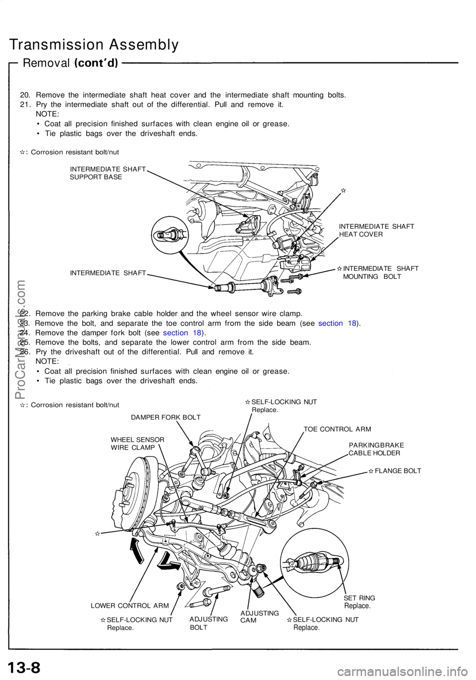
Transmission Assembly
Removal
20. Remove the intermediate shaft heat cover and the intermediate shaft mounting bolts.
21. Pry the intermediate shaft out of the differential. Pull and remove it. NOTE:
• Coat all precision finished surfaces with clean engine oil or grease.
• Tie plastic bags over the driveshaft ends.
Corrosion resistant bolt/nut
INTERMEDIATE SHAFT
SUPPORT BASE
INTERMEDIATE SHAFT INTERMEDIATE SHAFT
HEAT COVER
INTERMEDIATE SHAFT
MOUNTING BOLT
22. Remove the parking brake cable holder and the wheel sensor wire clamp.
23. Remove the bolt, and separate the toe control arm from the side beam (see section 18).
24. Remove the damper fork bolt (see section 18).
25. Remove the bolts, and separate the lower control arm from the side beam. 26. Pry the driveshaft out of the differential. Pull and remove it. NOTE:
• Coat all precision finished surfaces with clean engine oil or grease.
• Tie plastic bags over the driveshaft ends.
Corrosion resistant bolt/nut
DAMPER FORK BOLT SELF-LOCKING NUT
Replace.
TOE CONTROL ARM
WHEEL SENSOR WIRE CLAMP PARKING BRAKE
CABLE HOLDER
FLANGE BOLT
LOWER CONTROL ARM SELF-LOCKING NUTReplace. ADJUSTING
BOLT
ADJUSTING
CAM
SELF-LOCKING NUT
Replace.
SET RING
Replace.ProCarManuals.com
Page 404 of 1640
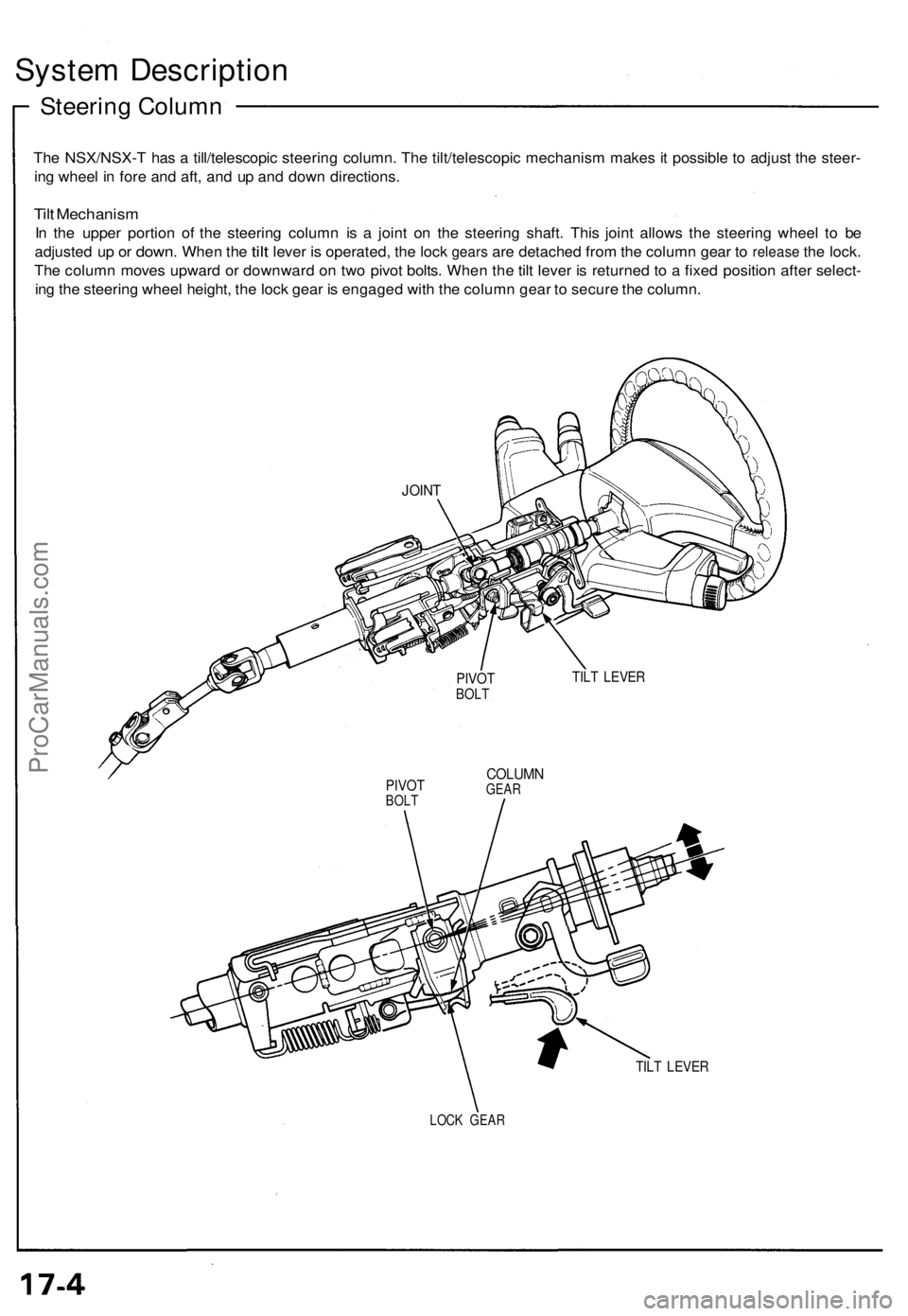
System Description
Steering Column
The NSX/NSX-T has a till/telescopic steering column. The tilt/telescopic mechanism makes it possible to adjust the steer-
ing wheel in fore and aft, and up and down directions.
Tilt Mechanism
In the upper portion of the steering column is a joint on the steering shaft. This joint allows the steering wheel to be
adjusted
up or
down.
When
the
tilt
lever
is
operated,
the
lock
gears
are
detached from
the
column gear
to
release
the
lock.
The column moves upward or downward on two pivot bolts. When the tilt lever is returned to a fixed position after select-
ing the steering wheel height, the lock gear is engaged with the column gear to secure the column.
TILT LEVER
PIVOT
BOLT
COLUMN
GEAR
TILT LEVER
LOCK GEAR
JOINT
PIVOT
BOLTProCarManuals.com
Page 430 of 1640
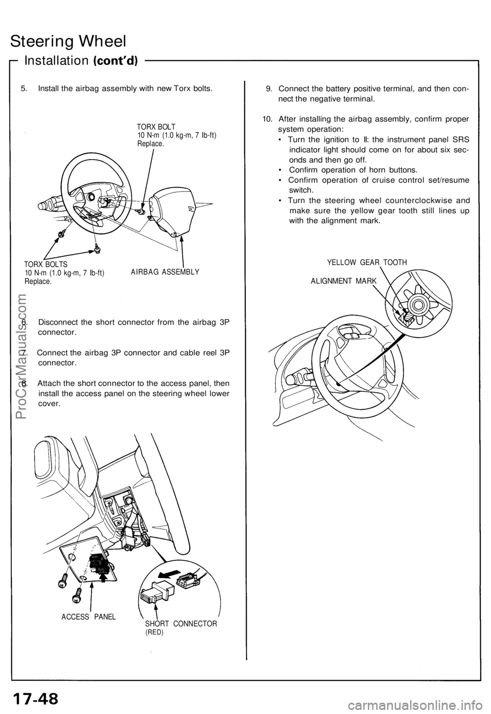
Steering Wheel
Installation
5. Install the airbag assembly with new Torx bolts.
TORX BOLT
10 N-m (1.0 kg-m, 7 Ib-ft)
Replace.
TORX BOLTS
10 N-m (1.0 kg-m, 7 Ib-ft)
Replace.
AIRBAG ASSEMBLY
6. Disconnect the short connector from the airbag 3P
connector.
7. Connect the airbag 3P connector and cable reel 3P
connector.
8. Attach the short connector to the access panel, then
install the access panel on the steering wheel lower
cover.
ACCESS PANEL
SHORT CONNECTOR
(RED)
9. Connect the battery positive terminal, and then con-
nect the negative terminal.
10. After installing the airbag assembly, confirm proper
system operation:
• Turn the ignition to II: the instrument panel SRS
indicator light should come on for about six sec-
onds and then go off.
• Confirm operation of horn buttons.
• Confirm operation of cruise control set/resume
switch.
• Turn the steering wheel counterclockwise and
make sure the yellow gear tooth still lines up
with the alignment mark.
YELLOW GEAR TOOTH
ALIGNMENT MARKProCarManuals.com
Page 437 of 1640
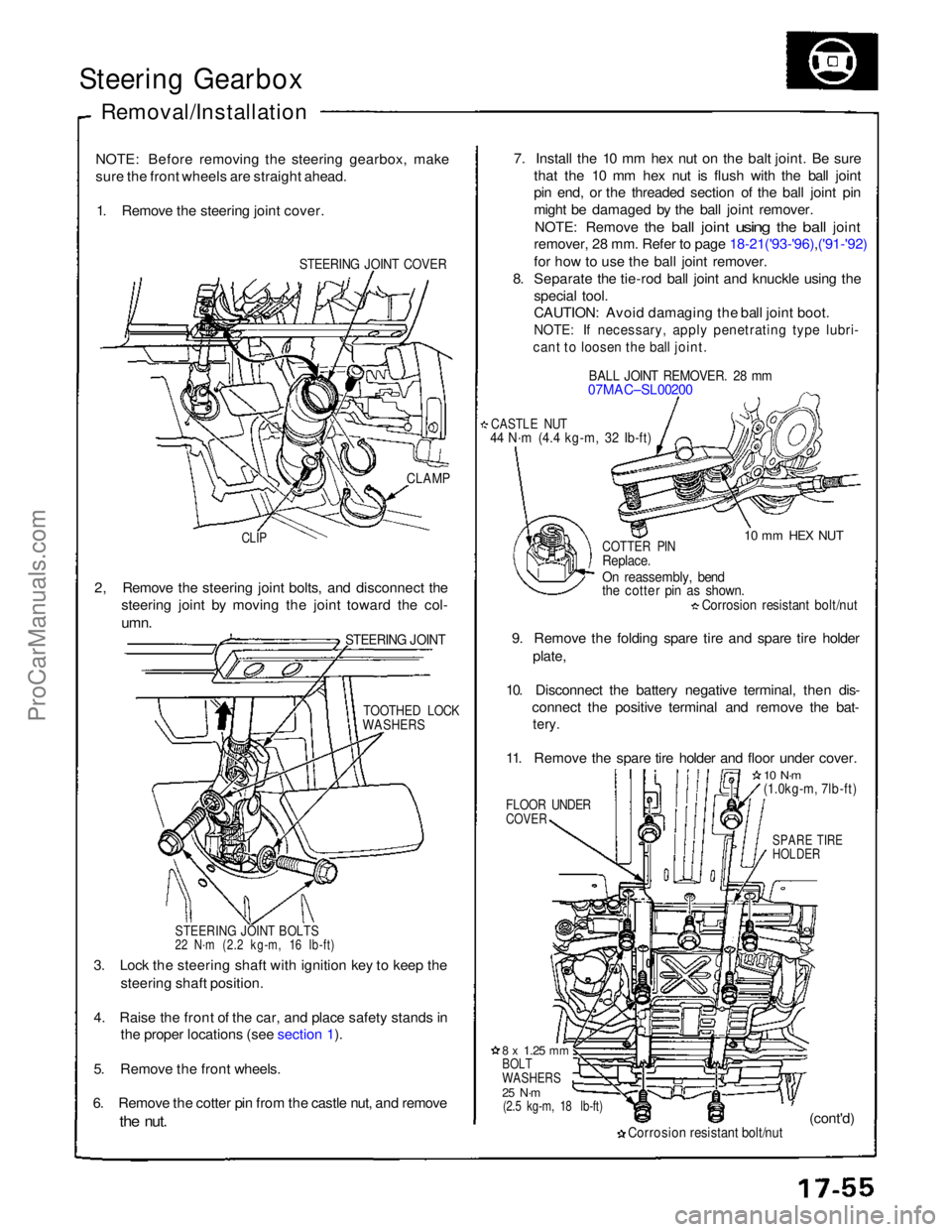
Steering Gearbox
Removal/Installation
NOTE: Before removing the steering gearbox, make
sure the front wheels are straight ahead. 1. Remove the steering joint cover.
STEERING JOINT COVER
7. Install the 10 mm hex nut on the balt joint. Be sure
that the 10 mm hex nut is flush with the ball joint
pin end, or the threaded section of the ball joint pin
might be damaged by the ball joint remover.
NOTE: Remove
the
ball
joint
using
the
ball
joint
remover, 28 mm. Refer to page 18-21('93-'96),('91-'92)
for how to use the ball joint remover.
8. Separate the tie-rod ball joint and knuckle using the
special tool.
CAUTION: Avoid damaging the ball joint boot.
NOTE: If necessary, apply penetrating type lubri-
cant to loosen the ball joint.
BALL JOINT REMOVER. 28 mm
07MAC–SL00200
CASTLE NUT
44 N·m (4.4 kg-m, 32 Ib-ft)
10 mm HEX NUT
CLAMP
CLIP
COTTER PIN
Replace.
On reassembly, bend
the cotter pin as shown.
Corrosion resistant bolt/nut
9. Remove the folding spare tire and spare tire holder plate,
10. Disconnect the battery negative terminal, then dis- connect the positive terminal and remove the bat-
tery.
11. Remove the spare tire holder and floor under cover.
FLOOR UNDER
COVER
10 N·m
(1.0kg-m, 7lb-ft)
SPARE TIRE
HOLDER
2, Remove the steering joint bolts, and disconnect the
steering joint by moving the joint toward the col-
umn.
STEERING JOINT
TOOTHED LOCK
WASHERS
STEERING JOINT BOLTS
22 N·m (2.2 kg-m, 16 Ib-ft)
3. Lock the steering shaft with ignition key to keep the steering shaft position.
4. Raise the front of the car, and place safety stands in the proper locations (see section 1).
5. Remove the front wheels.
6. Remove the cotter pin from the castle nut, and remove
the
nut.
8 x
1.25
mm
BOLT
WASHERS
25 N·m
(2.5 kg-m, 18 lb-ft)
Corrosion resistant bolt/nut
(cont'd)ProCarManuals.com