Page 1300 of 1640
Steering Wheel
Removal
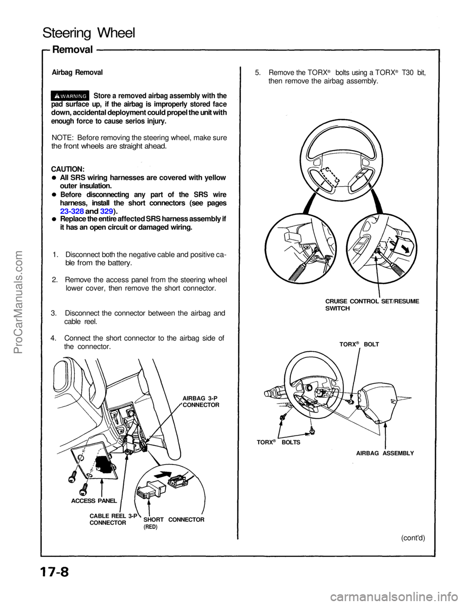
Airbag Removal
Store a removed airbag assembly with the
pad surface up, if the airbag is improperly stored face
down, accidental deployment could propel the unit with
enough force to cause serios injury.
NOTE: Before removing the steering wheel, make sure
the front wheels are straight ahead.
CAUTION:
All SRS wiring harnesses are covered with yellow
outer insulation.
Before disconnecting any part of the SRS wire
harness, install the short connectors (see pages
23-328 and 329).
Replace the entire affected SRS harness assembly if
it has an open circuit or damaged wiring.
1. Disconnect both the negative cable and positive ca-
ble from the battery.
2. Remove the access panel from the steering wheel lower cover, then remove the short connector.
3. Disconnect the connector between the airbag and cable reel.
4. Connect the short connector to the airbag side of the connector.
AIRBAG 3-PCONNECTOR
SHORT CONNECTOR
(RED)
CABLE REEL 3-P
CONNECTOR
ACCESS PANEL
CRUISE CONTROL SET/RESUME
SWITCH
TORX ®
BOLT
AIRBAG ASSEMBLY (cont'd)
5. Remove the TORX
®
bolts using a TORX ®
T30 bit,
then remove the airbag assembly.
TORX ®
BOLTSProCarManuals.com
Page 1304 of 1640
5.
Install
the
airbag assembly
with
new
TORX
®
bolts.
TORX ®
BOLT
10 N ·
m (1.0 kg-m, 7 Ib-ft)
Replace
TORX ®
BOLTS
10 N ·
m (1.0 kg-m, 7 Ib-ft)
Replace
AIRBAG ASSEMBLY
7. Disconnect the short connector from the airbag 3-P connector.
8. Connect the airbag 3-P connector and cable reel 3-P
connector.
9. Attach the short connector to the access panel, and install the access panel on the steering wheel
lower cover.
ACCESS PANEL SHORT CONNECTOR
(RED)
10. Connect the battery positive terminal and then con-
nect the negative terminal.
11. After installing the airbag assembly, confirm proper system operation:
Turn the ignition to II: the instrument panel SRSindicator light should come on for about 6
seconds and then go off.
Confirm operation of horn buttons.
Confirm operation of cruise control set/resume
switch.
Turn the steering wheel counterclockwise and
make sure the yellow gear tooth still lines up with
the alignment mark.
YELLOW GEAR TOOTH
ALIGNMENT MARKProCarManuals.com
Page 1312 of 1640
Manual Steering
Gearbox Removal/Installation
NOTE: Before removing the steering gearbox, make
sure the front wheels are straight ahead.
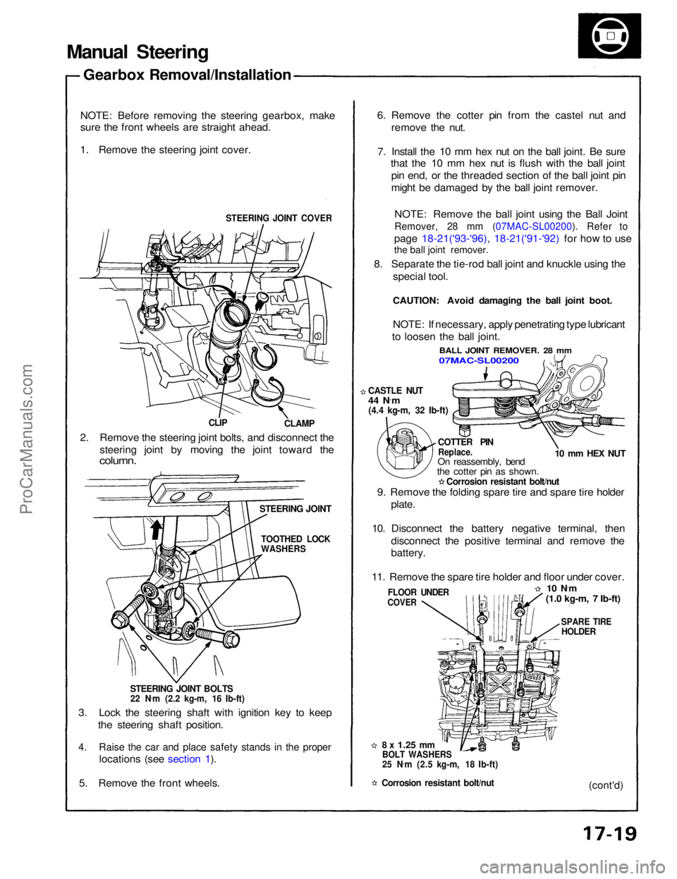
1. Remove the steering joint cover.
STEERING JOINT COVER
CLAMP
CLIP
2. Remove the steering joint bolts, and disconnect the steering joint by moving the joint toward the
column.
STEERING JOINT
STEERING JOINT BOLTS
22 N .
m (2.2 kg-m, 16 Ib-ft)
3. Lock the steering shaft with ignition key to keep the steering shaft position.
4. Raise the car and place safety stands in the proper
locations (see section 1).
5. Remove the front wheels.
8 x
1.25
mm
BOLT WASHERS
25 N .
m (2.5 kg-m, 18 Ib-ft)
Corrosion resistant bolt/nut
FLOOR UNDER
COVER
9. Remove the folding spare tire and spare tire holder
plate.
10. Disconnect the battery negative terminal, then disconnect the positive terminal and remove the
battery.
11. Remove the spare tire holder and floor under cover.
10 N·
m
(1.0 kg-m, 7 Ib-ft)
SPARE TIRE
HOLDER
(cont'd)
COTTER PIN
Replace.
On reassembly, bend
the cotter pin as shown.
Corrosion resistant bolt/nut
CASTLE NUT
44 N
·
m
(4.4 kg-m, 32 Ib-ft)
10 mm HEX NUT
NOTE: If necessary, apply penetrating type lubricant
to loosen the ball joint.
BALL JOINT REMOVER. 28 mm
07MAC-SL00200
6. Remove the cotter pin from the castel nut and
remove the nut.
7. Install the 10 mm hex nut on the ball joint. Be sure that the 10 mm hex nut is flush with the ball joint
pin end, or the threaded section of the ball joint pin
might be damaged by the ball joint remover.
NOTE: Remove the ball joint using the Ball Joint
Remover, 28 mm (07MAC-SL00200). Refer to
page 18-21('93-'96), 18-21('91-'92) for how to use
8. Separate the tie-rod ball joint and knuckle using the special tool.
CAUTION: Avoid damaging the ball joint boot.
TOOTHED LOCK
WASHERSProCarManuals.com
Page 1313 of 1640
Manual Steering
Gearbox Removal/Installation (Cont'd)
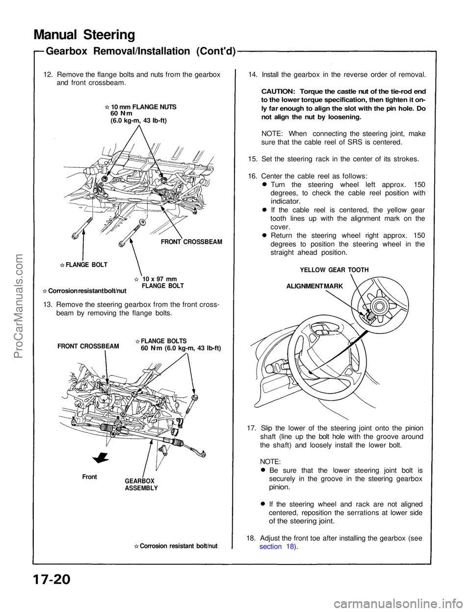
12. Remove the flange bolts and nuts from the gearbox and front crossbeam.
10 mm FLANGE NUTS
60 N ·
m
(6.0 kg-m, 43 Ib-ft)
FRONT CROSSBEAM
10 x 97 mm
FLANGE BOLT
FLANGE BOLT
Corrosion resistant bolt/nut
13. Remove the steering gearbox from the front cross- beam by removing the flange bolts.
FLANGE BOLTS
60 N.
m (6.0 kg-m, 43 Ib-ft)
FRONT CROSSBEAM
Front
GEARBOX
ASSEMBLY
Corrosion resistant bolt/nut
14. Install the gearbox in the reverse order of removal.
CAUTION: Torque the castle nut of the tie-rod end
to the lower torque specification, then tighten it on-
ly far enough to align the slot with the pin hole. Do
not align the nut by loosening.
NOTE: When connecting the steering joint, make
sure that the cable reel of SRS is centered.
15. Set the steering rack in the center of its strokes.
16. Center the cable reel as follows: Turn the steering wheel left approx. 150
degrees, to check the cable reel position with
indicator.
If the cable reel is centered, the yellow gear
tooth lines up with the alignment mark on the
cover.
Return the steering wheel right approx. 150
degrees to position the steering wheel in the
straight ahead position.
YELLOW GEAR TOOTH
ALIGNMENT MARK
17. Slip the lower of the steering joint onto the pinion shaft (line up the bolt hole with the groove around
the shaft) and loosely install the lower bolt.
NOTE:
Be sure that the lower steering joint bolt is
securely in the groove in the steering gearbox
pinion.
If the steering wheel and rack are not aligned
centered, reposition the serrations at lower side
of the steering joint.
18. Adjust the front toe after installing the gearbox (see section 18).ProCarManuals.com
Page 1340 of 1640
Power Steering
Gearbox Removal/Installation
NOTE: Before removing the steering gearbox, make
sure the front wheels are straight ahead.
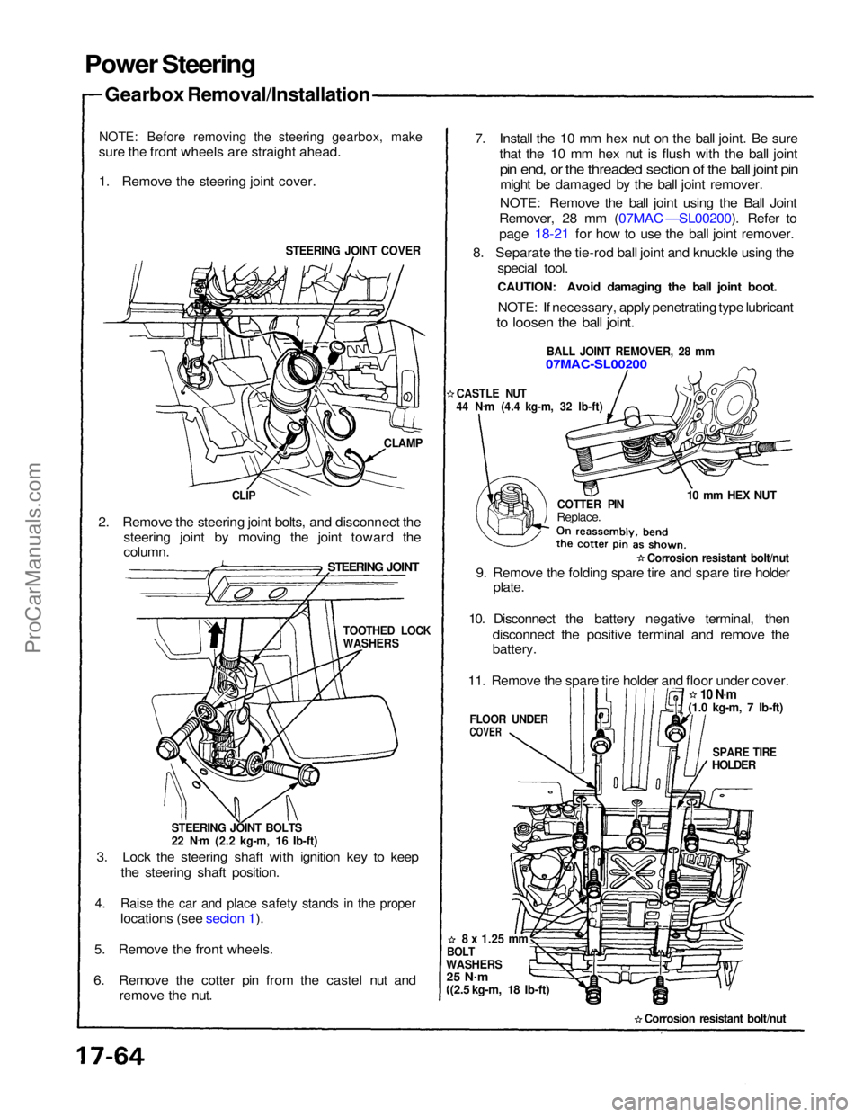
1. Remove the steering joint cover.
STEERING JOINT COVER
CLAMP
CLIP
2. Remove the steering joint bolts, and disconnect the steering joint by moving the joint toward the
STEERING JOINT
column.
STEERING JOINT BOLTS
22 N.
m (2.2 kg-m, 16 Ib-ft)
3. Lock the steering shaft with ignition key to keep the steering shaft position.
4. Raise the car and place safety stands in the proper
locations (see secion 1).
5. Remove the front wheels.
6. Remove the cotter pin from the castel nut and remove the nut. 7. Install the 10 mm hex nut on the ball joint. Be sure
that the 10 mm hex nut is flush with the ball joint
pin end, or the threaded section of the ball joint pin
might be damaged by the ball joint remover.
NOTE: Remove the ball joint using the Ball Joint
Remover, 28 mm (07MAC —SL00200). Refer to
page 18-21 for how to use the ball joint remover.
8. Separate the tie-rod ball joint and knuckle using the special tool.
CAUTION: Avoid damaging the ball joint boot.
NOTE: If necessary, apply penetrating type lubricant
to loosen the ball joint.
BALL JOINT REMOVER, 28 mm
07MAC-SL00200
CASTLE NUT
44 N .
m (4.4 kg-m, 32 Ib-ft)
COTTER PIN
Replace.
10 mm HEX NUT
Corrosion resistant bolt/nut
9. Remove the folding spare tire and spare tire holder plate.
10. Disconnect the battery negative terminal, then disconnect the positive terminal and remove the
battery.
11. Remove the spare tire holder and floor under cover.
10 N·m
SPARE TIRE
HOLDER
FLOOR UNDER
COVER
8 x
1.25
mm
BOLT
WASHERS
25 N .
m
(2.5 kg-m, 18 Ib-ft)
Corrosion resistant bolt/nut
TOOTHED LOCK
WASHERS
(1.0 kg-m, 7 Ib-ft)ProCarManuals.com
Page 1352 of 1640
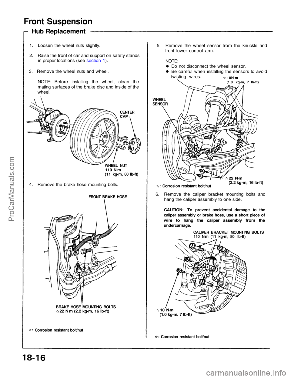
Front Suspension
Hub Replacement
1. Loosen the wheel nuts slightly.
2. Raise the front of car and support on safety stands in proper locations (see section 1).
3. Remove the wheel nuts and wheel. NOTE: Before installing the wheel, clean the
mating surfaces of the brake disc and inside of the
wheel.
CENTER
CAP
WHEEL NUT
110 N .
m
(11 kg-m, 80 lb-ft)
4. Remove the brake hose mounting bolts.
FRONT BRAKE HOSE
BRAKE HOSE MOUNTING BOLTS
Corrosion resistant bolt/nut
5. Remove the wheel sensor from the knuckle and
front lower control arm.
Do not disconnect the wheel sensor.
Be careful when installing the sensors to avoid
twisting wires. 10N.
m
(1.0 kg-m, 7 lb-ft)
WHEEL
SENSOR
22 N.
m
(2.2 kg-m, 16 Ib-ft)
Corrosion resistant bolt/nut
6. Remove the caliper bracket mounting bolts and hang the caliper assembly to one side.
CAUTION: To prevent accidental damage to the
caliper assembly or brake hose, use a short piece of
wire to hang the caliper assembly from the
undercarriage.
CALIPER BRACKET MOUNTING BOLTS
110 N .
m (11 kg-m, 80 Ib-ft)
10 N .
m
(1.0 kg-m. 7 Ib-ft)
Corrosion resistant bolt/nut
22 N
.
m (2.2 kg-m, 16 Ib-ft)
NOTE:ProCarManuals.com
Page 1353 of 1640
7. Remove the flat head screws.
Screw two 8x12 mm bolts into the disc to push it
away from the hub.
NOTE: Turn each bolt two turns at a time to pre-
vent cocking the disc excessively.
FLAT HEAD SCREW
6 x 1.0 mm
10N .
m (1.0 kg-m, 7 Ib-ft)
BRAKE DISC 8x12
mm
BOLTS
8. Remove the hub unit from the knuckle.
SELF-LOCKING NUT
10 x
1.25
mm
Replace.
65 N .
m (6.5 kg-m, 47 Ib-ft)
FRONT HUB UNIT
Corrosion resistant bolt/nut
Front Wheel Bearing Replacement:
1. Pry the spindle nut stake away from the spindle,
then remove the spindle nut.
SPINDLE NUT
26 x 1.5 mm
Replace. Unstake
2. Remove the pulser using a commercially available bearing puller.
PULSER
(cont'd)ProCarManuals.com
Page 1357 of 1640
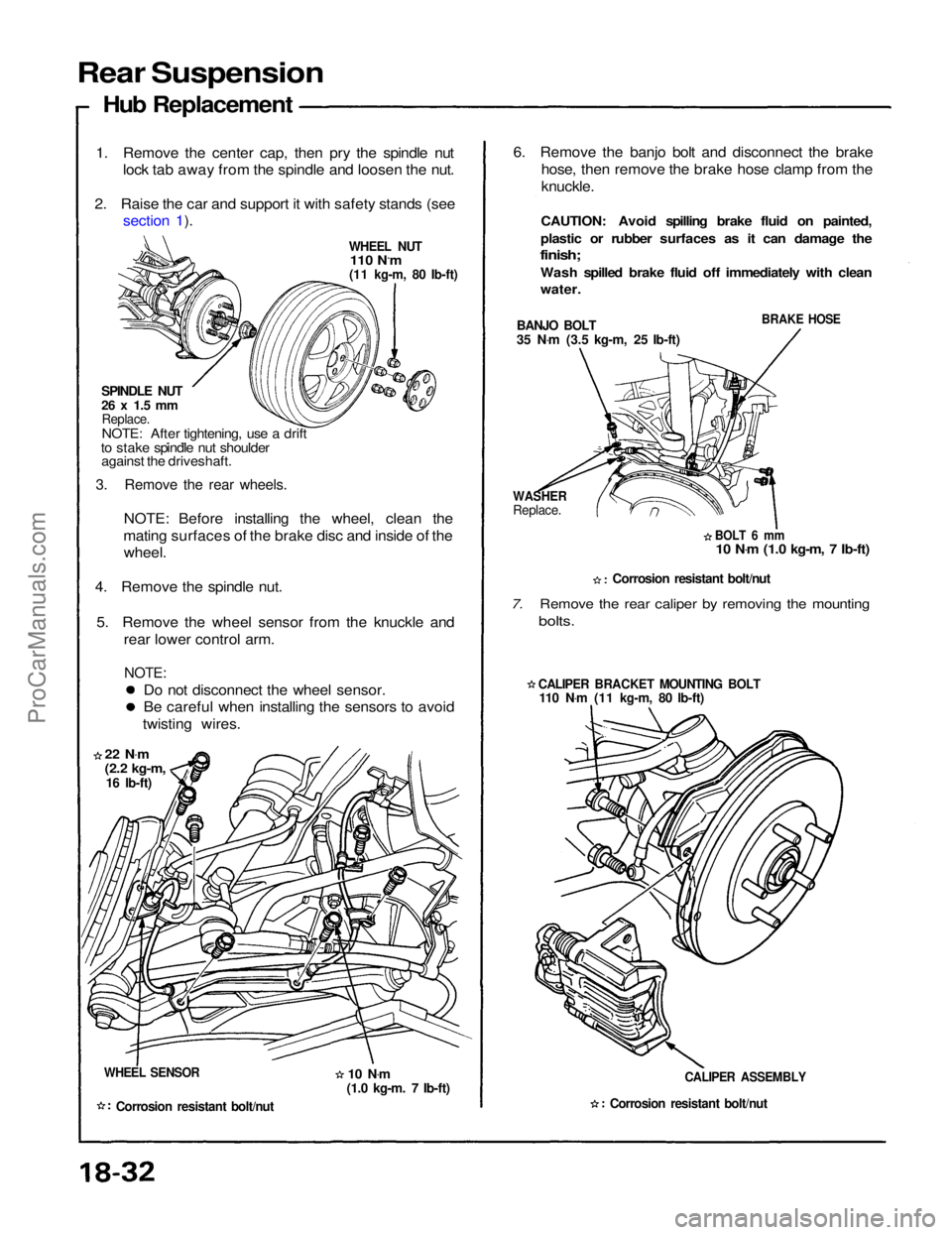
Rear Suspension
Hub Replacement
1. Remove the center cap, then pry the spindle nut
lock tab away from the spindle and loosen the nut.
2. Raise the car and support it with safety stands (see section 1).
WHEEL NUT
110 N.m
(11 kg-m, 80 Ib-ft)
SPINDLE NUT
26 x 1.5 mm
Replace.
NOTE: After tightening, use a drift
to stake spindle nut shoulder against the driveshaft.
3. Remove the rear wheels.
NOTE: Before installing the wheel, clean the
mating surfaces of the brake disc and inside of the wheel.
4. Remove the spindle nut.
5. Remove the wheel sensor from the knuckle and rear lower control arm.
NOTE:
Do not disconnect the wheel sensor.
Be careful when installing the sensors to avoid
twisting wires.
22 N .
m
(2.2 kg-m,
16 Ib-ft)
WHEEL SENSOR
Corrosion resistant bolt/nut
6. Remove the banjo bolt and disconnect the brake
hose, then remove the brake hose clamp from the
knuckle.
CAUTION: Avoid spilling brake fluid on painted,
plastic or rubber surfaces as it can damage the
finish;
Wash spilled brake fluid off immediately with clean
water.
BANJO BOLT
35 N .
m (3.5 kg-m, 25 Ib-ft)
BRAKE HOSE
WASHER
Replace.
BOLT 6 mm
10 N .
m (1.0 kg-m, 7 Ib-ft)
Corrosion resistant bolt/nut
7. Remove the rear caliper by removing the mounting
bolts.
CALIPER BRACKET MOUNTING BOLT
110 N .
m (11 kg-m, 80 Ib-ft)
CALIPER ASSEMBLY
Corrosion resistant bolt/nut
10 N
.
m
(1.0 kg-m. 7 Ib-ft)ProCarManuals.com