1991 ACURA NSX key battery
[x] Cancel search: key batteryPage 437 of 1640
Steering Gearbox
Removal/Installation
NOTE: Before removing the steering gearbox, make
sure the front wheels are straight ahead. 1. Remove the steering joint cover.
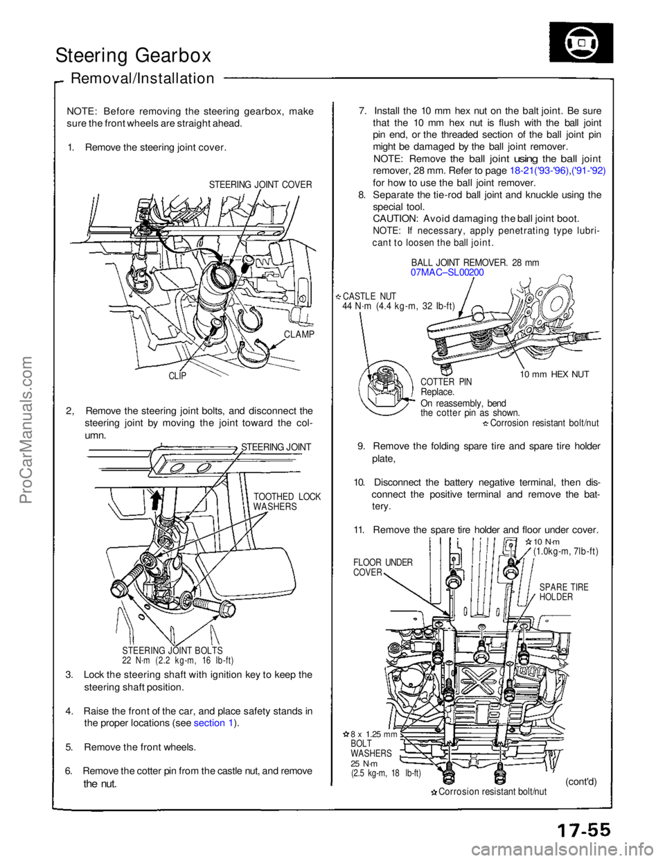
STEERING JOINT COVER
7. Install the 10 mm hex nut on the balt joint. Be sure
that the 10 mm hex nut is flush with the ball joint
pin end, or the threaded section of the ball joint pin
might be damaged by the ball joint remover.
NOTE: Remove
the
ball
joint
using
the
ball
joint
remover, 28 mm. Refer to page 18-21('93-'96),('91-'92)
for how to use the ball joint remover.
8. Separate the tie-rod ball joint and knuckle using the
special tool.
CAUTION: Avoid damaging the ball joint boot.
NOTE: If necessary, apply penetrating type lubri-
cant to loosen the ball joint.
BALL JOINT REMOVER. 28 mm
07MAC–SL00200
CASTLE NUT
44 N·m (4.4 kg-m, 32 Ib-ft)
10 mm HEX NUT
CLAMP
CLIP
COTTER PIN
Replace.
On reassembly, bend
the cotter pin as shown.
Corrosion resistant bolt/nut
9. Remove the folding spare tire and spare tire holder plate,
10. Disconnect the battery negative terminal, then dis- connect the positive terminal and remove the bat-
tery.
11. Remove the spare tire holder and floor under cover.
FLOOR UNDER
COVER
10 N·m
(1.0kg-m, 7lb-ft)
SPARE TIRE
HOLDER
2, Remove the steering joint bolts, and disconnect the
steering joint by moving the joint toward the col-
umn.
STEERING JOINT
TOOTHED LOCK
WASHERS
STEERING JOINT BOLTS
22 N·m (2.2 kg-m, 16 Ib-ft)
3. Lock the steering shaft with ignition key to keep the steering shaft position.
4. Raise the front of the car, and place safety stands in the proper locations (see section 1).
5. Remove the front wheels.
6. Remove the cotter pin from the castle nut, and remove
the
nut.
8 x
1.25
mm
BOLT
WASHERS
25 N·m
(2.5 kg-m, 18 lb-ft)
Corrosion resistant bolt/nut
(cont'd)ProCarManuals.com
Page 823 of 1640
Lights-on Reminder Systen.
Chime Test
NOTE: Refer to page 23-158 ('93-'96) ('91-'92) for a dia-
gram of the lights-o
n
reminder circuit, and page 23-166
for the input test of the circuit.
When the ignition key is turned off and removed with
the lights on, voltage is applied to the reminder circuit in
the integrated control unit. When you open the driver's
door, the circuit senses ground through the closed door
switch. With voltage at the "A6" terminal, ground at the "GRN/BLU 2
" terminal, and no voltage at the "A5" termi-
nal, the chime sounds to remind the driver to turn off
the lights.
1. Remove the dashboard lower cover, and disconnect the connectors.
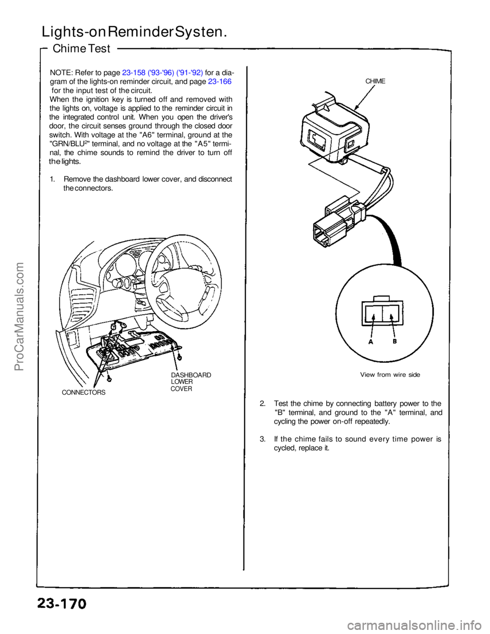
DASHBOARD
LOWER
COVER
CONNECTORS
CHIME
View from wire side
2. Test the chime by connecting battery power to the "B" terminal, and ground to the "A" terminal, and
cycling the power on-off repeatedly.
3. If the chime fails to sound every time power is cycled, replace it.ProCarManuals.com
Page 945 of 1640
Security Alarm System
Component Location Index
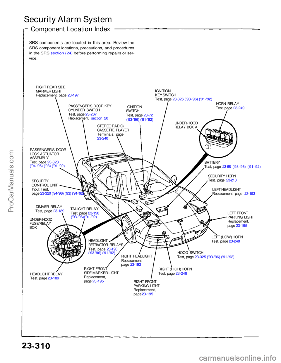
SRS components are located in this area. Review the
SRS component locations, precautions, and procedures
i
n
the SRS section (24) before performing repairs or ser-
vice.
RIGHT REAR SIDE
MARKER LIGHT
Replacement, page 23-197 PASSENGER'S DOOR KEY
CYLINDER SWITCH
Test, page 23-267
Replacement, section 20
STEREO RADIO/
CASSETTE PLAYER
Terminals, page
23-240
IGNITION
SWITCH
Test, page 23-72
('93-'96) ('91-'92)
IGNITION
KEY SWITCH
Test, page 23-326 ('93-'96) ('91-'92)
UNDER-HOOD
RELAY BOX A
HORN RELAY
Test, page 23-249
BATTERY
Teat, page 23-68 ('93-'96) ('91-'92)
SECURITY HORN
Test, page 23-218 LEFT HEADLIGHT
Replacement page 23-193
LEFT FRONT
PARKING LIGHT
Replacement,
page 23-195
LEFT (LOW) HORN
Test, page 23-248
HOOD SWITCH
Test, page 23-325 ('93-'96) ('91-'92)
RIGHT (HIGH) HORN
Test, page 23-248
RIGHT FRONT
PARKING LIGHT
Replacement,
page 23-195
RIGHT HEADLIGHT
Replacement,
page 23-193
RIGHT FRONT
SIDE MARKER LIGHT
Replacement,
page 23-195 HEADLIGHT
RETRACTOR RELAYS
Test, page 23-190
('93-'96) ('91-'92)
HEADLIGHT RELAY
Test, page 23-189 TAILIGHT RELAY
Test, page 23-190
('93-'96)('91-'92)
UNDER-HOOD
FUSE/RELAY
BOX
DIMMER RELAY
Test, page 23-189
SECURITY
CONTROL UNIT
Input Test,
page 23-320 ('94-'96) ('93) ('91-'92)
PASSENGER'S DOOR
LOCK ACTUATOR
ASSEMBLY
Test, page 23-323
('94-'96) ('93) ('91-'92)ProCarManuals.com
Page 1312 of 1640
Manual Steering
Gearbox Removal/Installation
NOTE: Before removing the steering gearbox, make
sure the front wheels are straight ahead.
1. Remove the steering joint cover.
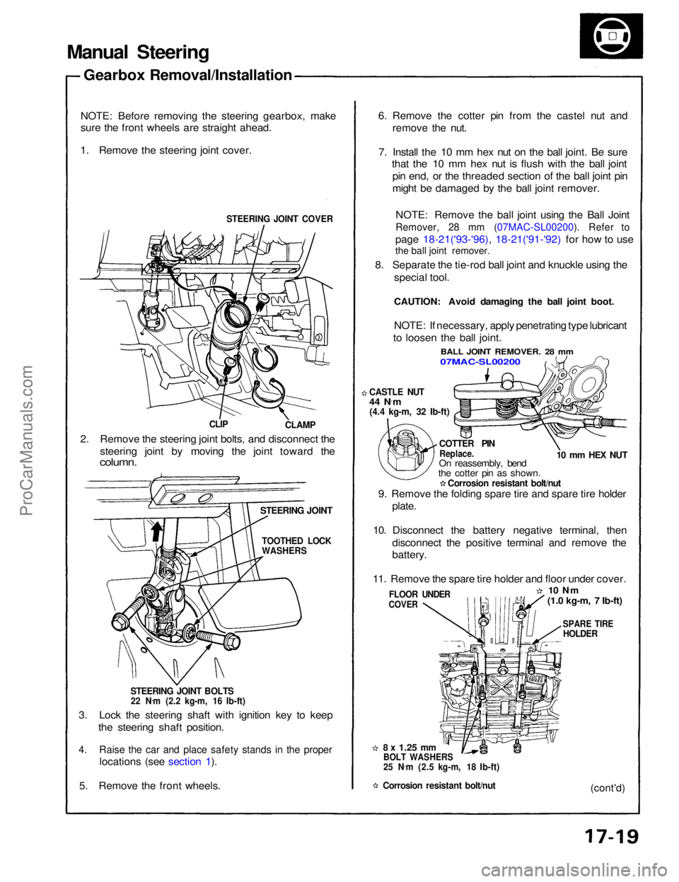
STEERING JOINT COVER
CLAMP
CLIP
2. Remove the steering joint bolts, and disconnect the steering joint by moving the joint toward the
column.
STEERING JOINT
STEERING JOINT BOLTS
22 N .
m (2.2 kg-m, 16 Ib-ft)
3. Lock the steering shaft with ignition key to keep the steering shaft position.
4. Raise the car and place safety stands in the proper
locations (see section 1).
5. Remove the front wheels.
8 x
1.25
mm
BOLT WASHERS
25 N .
m (2.5 kg-m, 18 Ib-ft)
Corrosion resistant bolt/nut
FLOOR UNDER
COVER
9. Remove the folding spare tire and spare tire holder
plate.
10. Disconnect the battery negative terminal, then disconnect the positive terminal and remove the
battery.
11. Remove the spare tire holder and floor under cover.
10 N·
m
(1.0 kg-m, 7 Ib-ft)
SPARE TIRE
HOLDER
(cont'd)
COTTER PIN
Replace.
On reassembly, bend
the cotter pin as shown.
Corrosion resistant bolt/nut
CASTLE NUT
44 N
·
m
(4.4 kg-m, 32 Ib-ft)
10 mm HEX NUT
NOTE: If necessary, apply penetrating type lubricant
to loosen the ball joint.
BALL JOINT REMOVER. 28 mm
07MAC-SL00200
6. Remove the cotter pin from the castel nut and
remove the nut.
7. Install the 10 mm hex nut on the ball joint. Be sure that the 10 mm hex nut is flush with the ball joint
pin end, or the threaded section of the ball joint pin
might be damaged by the ball joint remover.
NOTE: Remove the ball joint using the Ball Joint
Remover, 28 mm (07MAC-SL00200). Refer to
page 18-21('93-'96), 18-21('91-'92) for how to use
8. Separate the tie-rod ball joint and knuckle using the special tool.
CAUTION: Avoid damaging the ball joint boot.
TOOTHED LOCK
WASHERSProCarManuals.com
Page 1340 of 1640
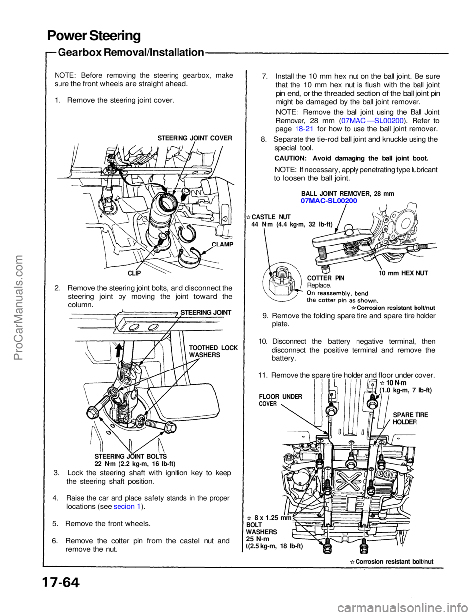
Power Steering
Gearbox Removal/Installation
NOTE: Before removing the steering gearbox, make
sure the front wheels are straight ahead.
1. Remove the steering joint cover.
STEERING JOINT COVER
CLAMP
CLIP
2. Remove the steering joint bolts, and disconnect the steering joint by moving the joint toward the
STEERING JOINT
column.
STEERING JOINT BOLTS
22 N.
m (2.2 kg-m, 16 Ib-ft)
3. Lock the steering shaft with ignition key to keep the steering shaft position.
4. Raise the car and place safety stands in the proper
locations (see secion 1).
5. Remove the front wheels.
6. Remove the cotter pin from the castel nut and remove the nut. 7. Install the 10 mm hex nut on the ball joint. Be sure
that the 10 mm hex nut is flush with the ball joint
pin end, or the threaded section of the ball joint pin
might be damaged by the ball joint remover.
NOTE: Remove the ball joint using the Ball Joint
Remover, 28 mm (07MAC —SL00200). Refer to
page 18-21 for how to use the ball joint remover.
8. Separate the tie-rod ball joint and knuckle using the special tool.
CAUTION: Avoid damaging the ball joint boot.
NOTE: If necessary, apply penetrating type lubricant
to loosen the ball joint.
BALL JOINT REMOVER, 28 mm
07MAC-SL00200
CASTLE NUT
44 N .
m (4.4 kg-m, 32 Ib-ft)
COTTER PIN
Replace.
10 mm HEX NUT
Corrosion resistant bolt/nut
9. Remove the folding spare tire and spare tire holder plate.
10. Disconnect the battery negative terminal, then disconnect the positive terminal and remove the
battery.
11. Remove the spare tire holder and floor under cover.
10 N·m
SPARE TIRE
HOLDER
FLOOR UNDER
COVER
8 x
1.25
mm
BOLT
WASHERS
25 N .
m
(2.5 kg-m, 18 Ib-ft)
Corrosion resistant bolt/nut
TOOTHED LOCK
WASHERS
(1.0 kg-m, 7 Ib-ft)ProCarManuals.com
Page 1426 of 1640
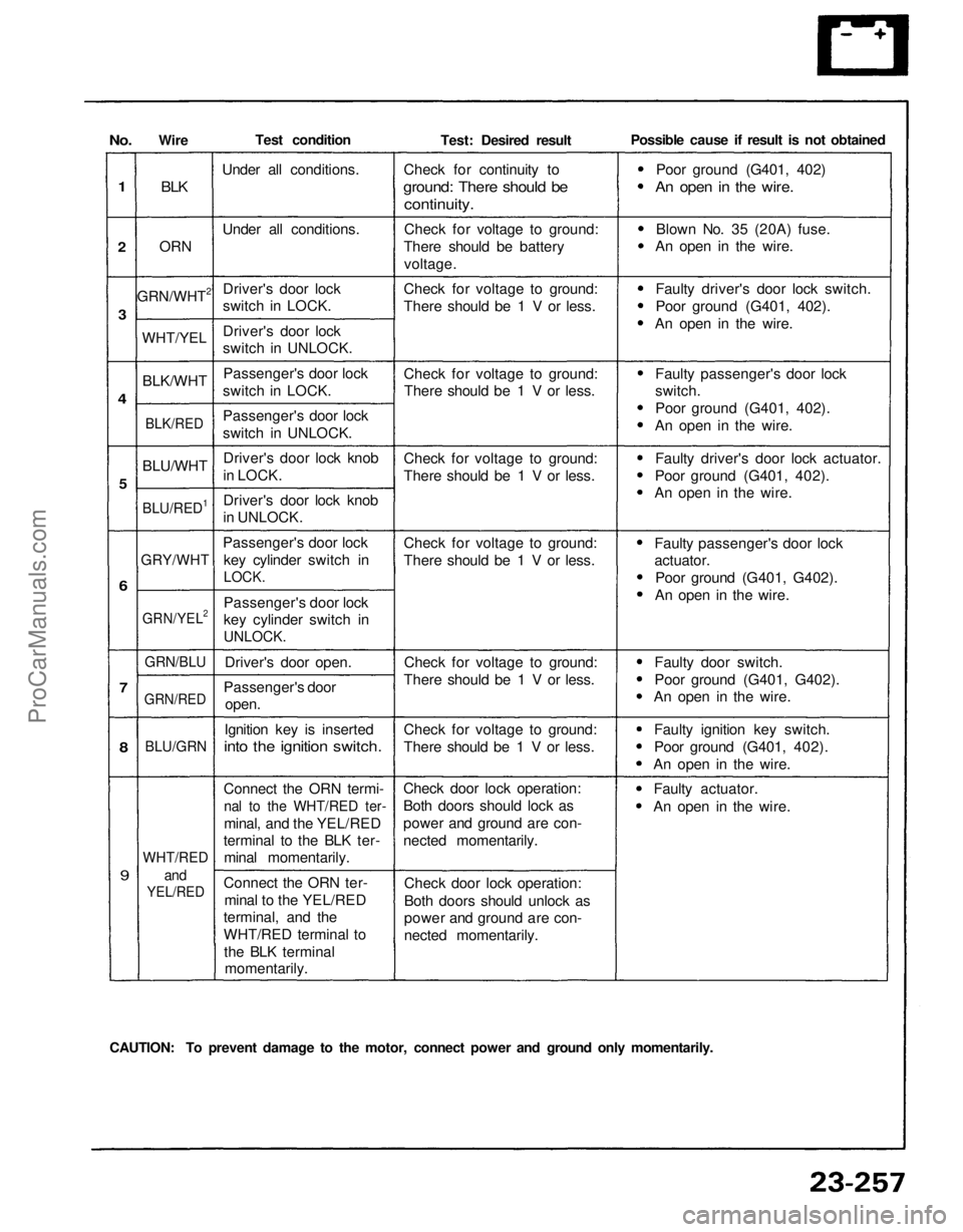
No.
1
2
3
4
5
6
7
8
9
Wire
BLK
ORN
GRN/WHT2
WHT/YEL
BLK/WHT
BLK/RED
BLU/WHT
BLU/RED1
GRY/WHT
GRN/YEL2
GRN/BLU
GRN/RED
BLU/GRN
WHT/RED
and
YEL/RED
Test condition
Under all conditions.
Under all conditions.Driver's door lock
switch in LOCK.
Driver's door lock
switch in UNLOCK.Passenger's door lock
switch in LOCK.
Passenger's door lock
switch in UNLOCK.
Driver's door lock knob
in LOCK.
Driver's door lock knob
in UNLOCK.
Passenger's door lock key cylinder switch in
LOCK.
Passenger's door lock
key cylinder switch in
UNLOCK.
Driver's door open.
Passenger's door open.
Ignition key is inserted
into the ignition switch.
Connect the ORN termi-
nal to the WHT/RED ter-
minal, and the YEL/RED
terminal to the BLK ter- minal momentarily.
Connect the ORN ter- minal to the YEL/RED
terminal, and the
WHT/RED terminal to
the BLK terminal momentarily. Test: Desired result
Check for continuity to
ground: There should be
continuity.
Check for voltage to ground:
There should be battery
voltage.
Check for voltage to ground:
There should be 1 V or less.
Check for voltage to ground: There should be 1 V or less.
Check for voltage to ground:
There should be 1 V or less.
Check for voltage to ground:
There should be 1 V or less.
Check for voltage to ground:
There should be 1 V or less.
Check for voltage to ground:
There should be 1 V or less.
Check door lock operation:
Both doors should lock as
power and ground are con-
nected momentarily.
Check door lock operation:
Both doors should unlock as
power and ground are con-
nected momentarily. Possible cause if result is not obtained
Poor ground (G401, 402)
An open in the wire.
Blown No. 35 (20A) fuse.
An open in the wire.
Faulty driver's door lock switch.
Poor ground (G401, 402).
An open in the wire.
Faulty passenger's door lock
switch.
Poor ground (G401, 402).
An open in the wire.
Faulty driver's door lock actuator.
Poor ground (G401, 402).
An open in the wire.
Faulty passenger's door lock
actuator.
Poor ground (G401, G402).
An open in the wire.
Faulty door switch.
Poor ground (G401, G402).
An open in the wire.
Faulty ignition key switch.
Poor ground (G401, 402).
An open in the wire.
Faulty actuator.
An open in the wire.
CAUTION: To prevent damage to the motor, connect power and ground only momentarily.ProCarManuals.com