Page 461 of 1640
Front Suspensio n
Hub Replacemen t
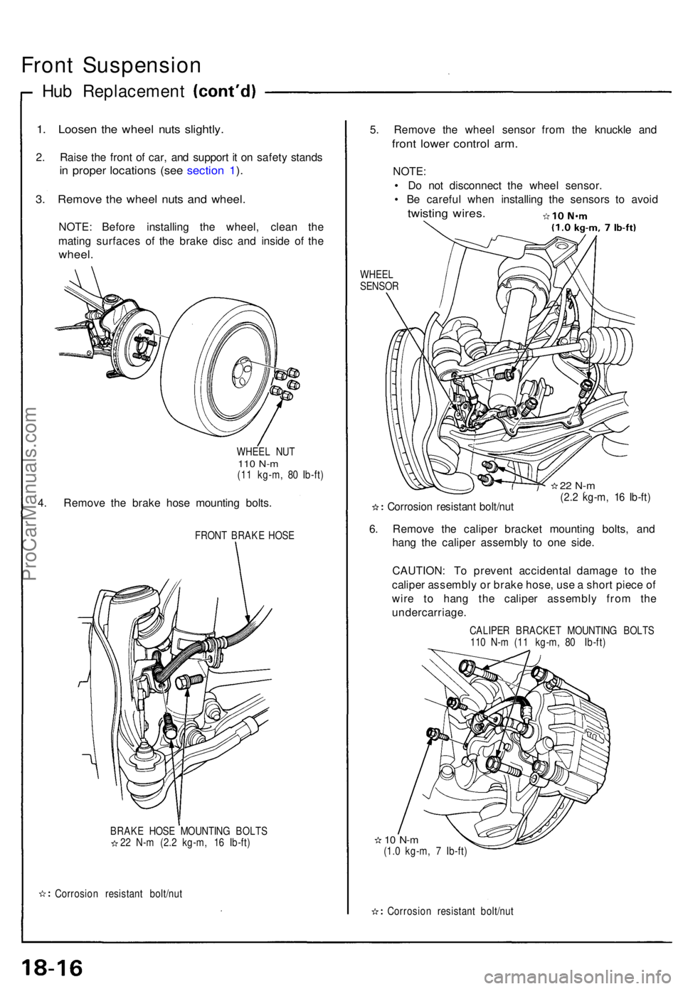
1. Loose n th e whee l nut s slightly .
2. Rais e th e fron t o f car , an d suppor t i t o n safet y stand s
in prope r location s (se e sectio n 1 ).
3 . Remov e th e whee l nut s an d wheel .
NOTE: Befor e installin g th e wheel , clea n th e
matin g surface s o f th e brak e dis c an d insid e o f th e
wheel .
WHEE L NU T110 N- m(11 kg-m , 8 0 Ib-ft )
4. Remov e th e brak e hos e mountin g bolts .
FRON T BRAK E HOS E
BRAK E HOS E MOUNTIN G BOLT S
2 2 N- m (2. 2 kg-m , 1 6 Ib-ft )
Corrosio n resistan t bolt/nu t
5. Remov e th e whee l senso r fro m th e knuckl e an d
fron t lowe r contro l arm .
NOTE :
• D o no t disconnec t th e whee l sensor .
• B e carefu l whe n installin g th e sensor s t o avoi d
twistin g wires .
WHEE L
SENSO R
Corrosio n resistan t bolt/nu t
22 N- m(2.2 kg-m , 1 6 Ib-ft )
6. Remov e th e calipe r bracke t mountin g bolts , an d
han g th e calipe r assembl y t o on e side .
CAUTION : T o preven t accidenta l damag e t o th e
calipe r assembl y o r brak e hose , us e a shor t piec e o f
wir e t o han g th e calipe r assembl y fro m th e
undercarriage .
CALIPER BRACKE T MOUNTIN G BOLT S
11 0 N- m (1 1 kg-m , 8 0 Ib-ft )
10 N- m(1.0 kg-m , 7 Ib-ft )
Corrosio n resistan t bolt/nu t
ProCarManuals.com
Page 462 of 1640
7. Remove the flat head screws.
Screw two 8 x 12 mm bolts into the disc to push it
away from the hub.
NOTE: Turn each bolt two turns at a time to pre-
vent cocking the disc excessively.
FLAT HEAD SCREW
6 x 1.0 mm
10 N-m (1.0 kg-m, 7 Ib-ft)
BRAKE DISC
8. Remove the hub unit from the knuckle.
8 x 12 mm
BOLTS
SELF-LOCKING NUT
10 x
1.25
mm
Replace.
65 N-m (6.5 kg-m, 47 Ib-ft)
FRONT HUB UNIT
Corrosion resistant bolt/nut
Front Wheel Bearing Replacement:
1. Raise the locking tab on the spindle nut, then remove
the
nut.
SPINDLE NUT
26 x 1.5 mm
Replace.
Unstake
2. Remove the pulser using a commercially-available
bearing puller.
PULSER
TWO-JAW
PULLER
(Commercially
available)ProCarManuals.com
Page 477 of 1640
Rear Suspensio n
Hub Replacemen t
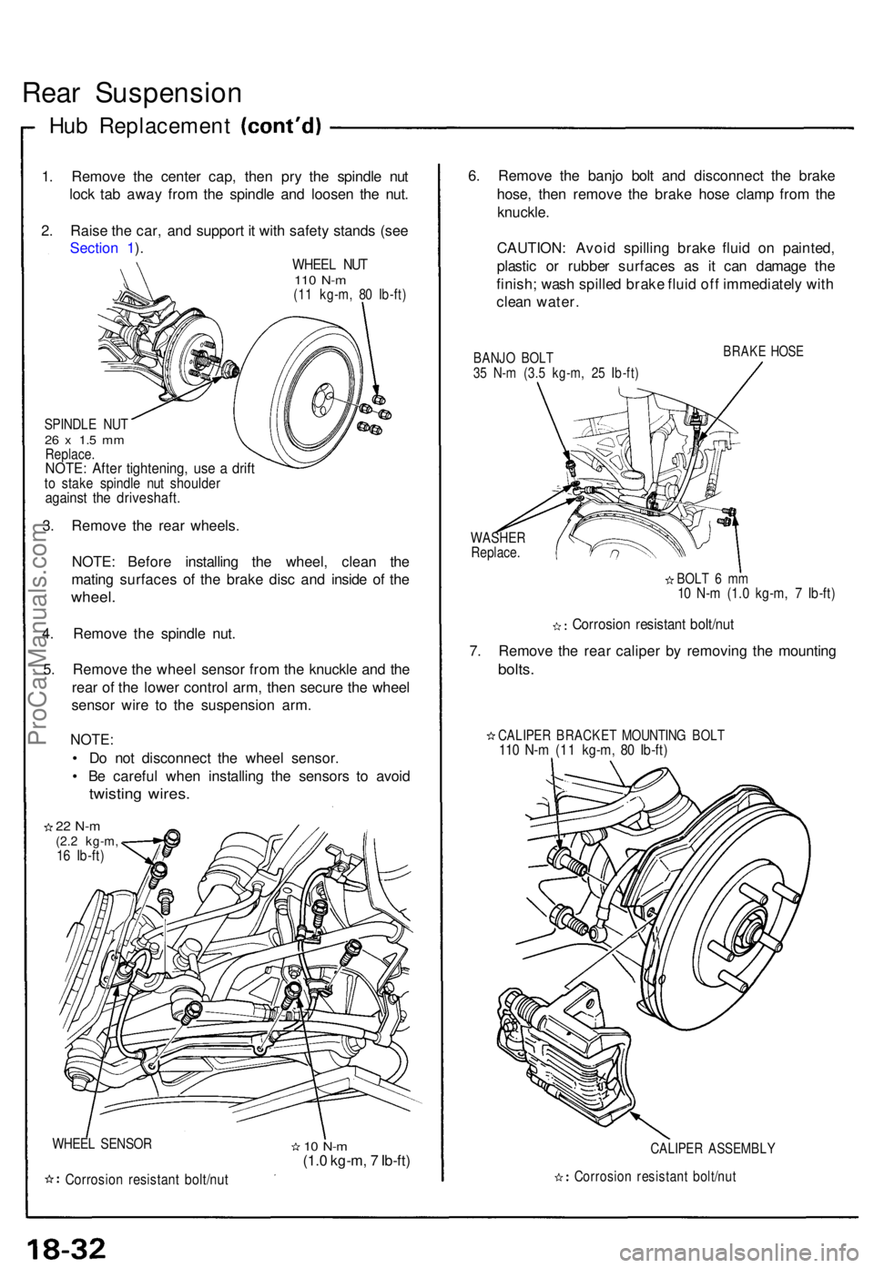
1. Remov e th e cente r cap , the n pr y th e spindl e nu t
loc k ta b awa y fro m th e spindl e an d loose n th e nut .
2 . Rais e th e car , an d suppor t i t wit h safet y stand s (se e
Sectio n 1 ).
WHEE L NU T110 N- m(11 kg-m , 8 0 Ib-ft )
SPINDL E NU T26 x 1. 5 m mReplace .NOTE: Afte r tightening , us e a drif tto stak e spindl e nu t shoulde ragainst th e driveshaft .
3. Remov e th e rea r wheels .
NOTE : Befor e installin g th e wheel, clean th e
matin g surface s o f th e brak e dis c an d insid e o f th e
wheel .
4. Remov e th e spindl e nut .
5 . Remov e th e whee l senso r fro m th e knuckl e an d th e
rea r o f th e lowe r contro l arm , the n secur e th e whee l
senso r wir e t o th e suspensio n arm .
NOTE :
• D o no t disconnec t th e whee l sensor .
• B e carefu l whe n installin g th e sensor s t o avoi d
twistin g wires .
22 N- m(2.2 kg-m ,16 Ib-ft )
WHEE L SENSO R
Corrosio n resistan t bolt/nu t
10 N- m(1.0 kg-m , 7 Ib-ft ) 6
. Remov e th e banj o bol t an d disconnec t th e brak e
hose , the n remov e th e brak e hos e clam p fro m th e
knuckle .
CAUTION : Avoi d spillin g brak e flui d o n painted ,
plasti c o r rubbe r surface s a s i t ca n damag e th e
finish ; was h spille d brak e flui d of f immediatel y wit h
clea n water .
BANJO BOL T35 N- m (3. 5 kg-m , 2 5 Ib-ft )
BRAK E HOS E
WASHE RReplace.
BOLT 6 m m10 N- m (1. 0 kg-m , 7 Ib-ft )
Corrosio n resistan t bolt/nu t
7. Remov e th e rea r calipe r b y removin g th e mountin g
bolts.
CALIPE R BRACKE T MOUNTIN G BOL T110 N- m (1 1 kg-m , 8 0 Ib-ft )
CALIPE R ASSEMBL Y
Corrosion resistan t bolt/nu t
ProCarManuals.com
Page 495 of 1640
Front Brak e Pad s
Inspection/Replacemen t
• Neve r us e a n ai r hos e o r dr y brus h t o clea n brak e
assemblies .
• Us e a n OSHA-approve d vacuu m cleane r t o avoi d
breathin g brak e dust .
1 . Loose n th e fron t whee l nut s slightly , the n rais e eac h
sid e o f th e ca r an d suppor t i t o n safet y stand s (se e
pag e 1-9 throug h 1-11 ). Remov e th e fron t wheels .
2 . I f th e brak e pa d thicknes s i s les s tha n servic e limi t
a t ste p 5 , replac e th e fron t pad s a s a set . 3
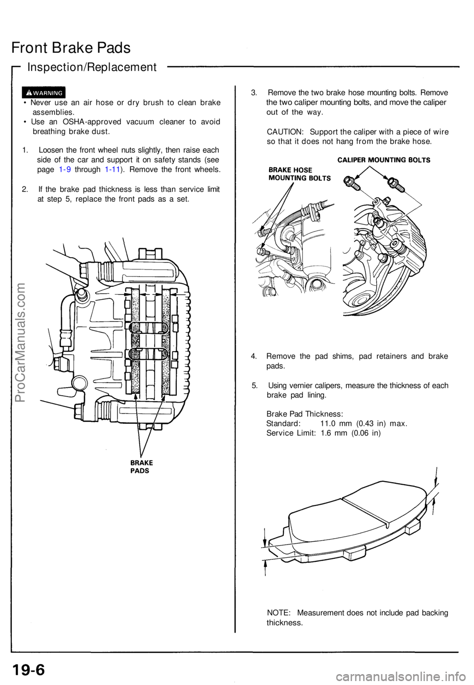
. Remov e th e tw o brak e hos e mountin g bolts . Remov e
the tw o calipe r mountin g bolts , an d mov e th e calipe r
out o f th e way .
CAUTION : Suppor t th e calipe r wit h a piec e o f wir e
s o tha t i t doe s no t han g fro m th e brak e hose .
4 . Remov e th e pa d shims , pa d retainer s an d brak e
pads .
5 . Usin g vernie r calipers , measur e th e thicknes s o f eac h
brak e pa d lining .
Brak e Pa d Thickness :
Standard : 11. 0 m m (0.4 3 in ) max .
Servic e Limit : 1. 6 m m (0.0 6 in )
NOTE : Measuremen t doe s no t includ e pa d backin g
thickness .
ProCarManuals.com
Page 496 of 1640
6. Clea n th e calipe r thoroughly ; remov e an y rust , an d
chec k fo r groove s an d cracks .
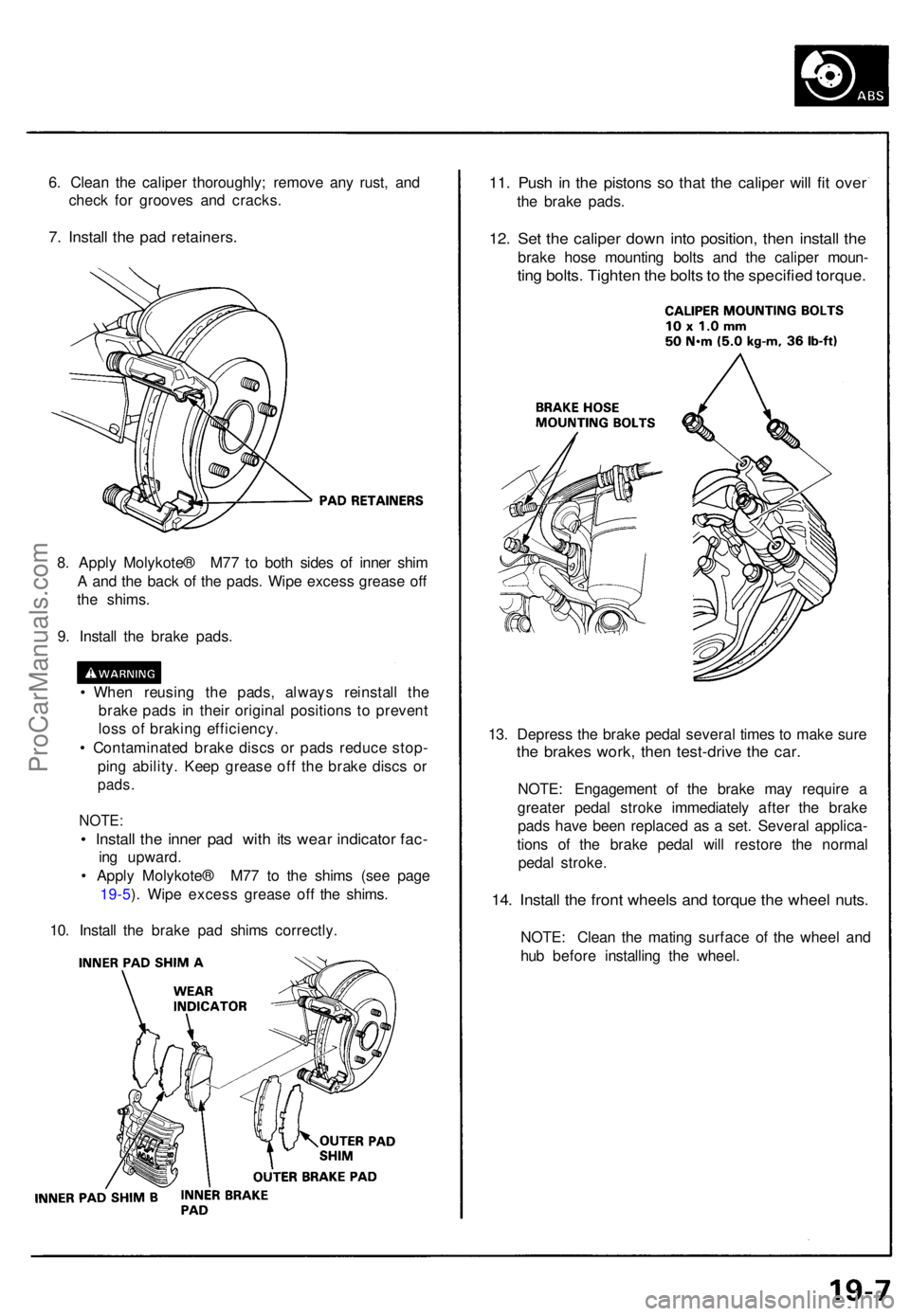
7. Instal l th e pa d retainers .
11. Pus h i n th e piston s s o tha t th e calipe r wil l fi t ove r
the brak e pads .
12. Se t th e calipe r dow n int o position , the n instal l th e
brak e hos e mountin g bolt s an d th e calipe r moun -
ting bolts . Tighte n th e bolt s to th e specifie d torque .
8. Appl y Molykote ® M7 7 t o bot h side s o f inne r shi m
A an d th e bac k o f th e pads . Wip e exces s greas e of f
th e shims .
9 . Instal l th e brak e pads .
• Whe n reusin g th e pads , alway s reinstal l th e
brak e pad s i n thei r origina l position s t o preven t
los s o f brakin g efficiency .
• Contaminate d brak e disc s o r pad s reduc e stop -
pin g ability . Kee p greas e of f th e brak e disc s o r
pads .
NOTE :
• Instal l th e inne r pa d wit h it s wea r indicato r fac -
ing upward .
• Appl y Molykote ® M7 7 t o th e shim s (se e pag e
19-5 ). Wip e exces s greas e of f th e shims .
10 . Instal l th e brak e pa d shim s correctly . 13
. Depres s th e brak e peda l severa l time s t o mak e sur e
the brake s work , the n test-driv e th e car .
NOTE : Engagemen t of the brak e ma y requir e a
greate r peda l strok e immediatel y afte r th e brak e
pad s hav e bee n replace d a s a set . Severa l applica -
tion s of the brak e peda l wil l restor e th e norma l
peda l stroke .
14. Instal l th e fron t wheel s an d torqu e th e whee l nuts .
NOTE : Clea n th e matin g surfac e o f th e whee l an d
hu b befor e installin g th e wheel .
ProCarManuals.com
Page 507 of 1640
11. Install and tighten the two caliper mounting bolts.
12. Insert the cable through the arm, and connect the
cable to the lever with the clevis pin and new lock
pin.
Install the new cable clip securely.
13. Install the caliper shield.
14. Depress the brake pedal several times to make sure
the brakes work, then test-drive the car.
NOTE: Engagement of the brake may require a
greater pedal stroke immediately after the brake
pads have been replaced as a set. Several applica-
tions of the brake pedal will restore the normal
pedal stroke.
1 5. Install the rear wheels and torque the wheel nuts.
NOTE: Clean the mating surfaces of the wheel and
hub before installing the wheel.ProCarManuals.com
Page 745 of 1640
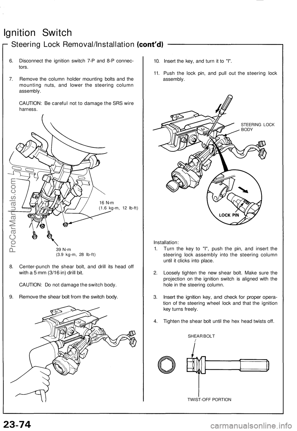
Ignition Switch
Steering Lock Removal/Installation
6. Disconnect the ignition switch 7-P and 8-P connec-
tors.
7. Remove the column holder mounting bolts and the
mounting nuts, and lower the steering column
assembly.
CAUTION: Be careful not to damage the SRS wire
harness.
16 N-m
(1.6 kg-m, 12 Ib-ft)
39 N-m
(3.9 kg-m, 28 Ib-ft)
8. Center-punch the shear bolt, and drill its head off
with a 5 mm (3/16 in) drill bit.
CAUTION: Do not damage the switch body.
9. Remove the shear bolt from the switch body.
10. Insert the key, and turn it to "I".
11. Push the lock pin, and pull out the steering lock
assembly.
STEERING LOCK
BODY
Installation:
1. Turn the key to "I", push the pin, and insert the
steering lock assembly into the steering column
until it clicks into place.
2. Loosely tighten the new shear bolt. Make sure the
projection on the ignition switch is aligned with the
hole in the steering column.
3. Insert the ignition key, and check for proper opera-
tion of the steering wheel lock and that the ignition
key turns freely.
4. Tighten the shear bolt until the hex head twists off.
SHEAR BOLT
/
TWIST-OFF PORTIONProCarManuals.com
Page 998 of 1640
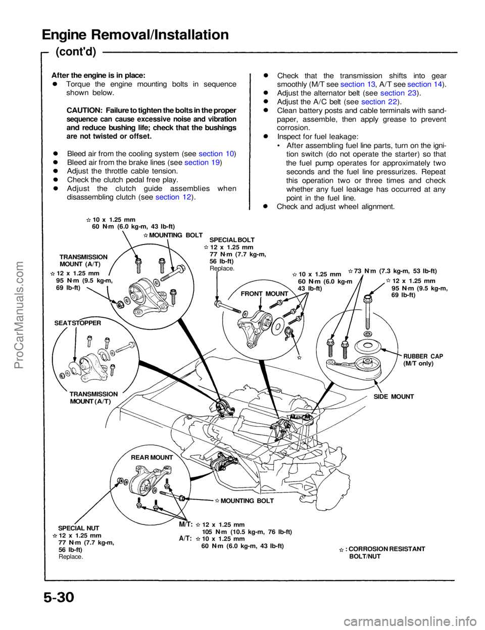
Engine Removal/Installation
(cont'd)
Torque the engine mounting bolts in sequenceshown below.
CAUTION: Failure to tighten the bolts in the proper
sequence can cause excessive noise and vibration
and reduce bushing life; check that the bushings
are not twisted or offset.
Bleed air from the cooling system (see section 10)
Bleed air from the brake lines (see section 19)
Adjust the throttle cable tension.
Check the clutch pedal free play.
Adjust the clutch guide assemblies when
disassembling clutch (see section 12). Check that the transmission shifts into gear
smoothly (M/T see section 13, A/T see section 14).
Adjust the alternator belt (see section 23).
Adjust the A/C belt (see section 22).
Clean battery posts and cable terminals with sand-
paper, assemble, then apply grease to prevent
corrosion.
Inspect for fuel leakage:
• After assembling fuel line parts, turn on the igni- tion switch (do not operate the starter) so that
the fuel pump operates for approximately two seconds and the fuel line pressurizes. Repeat
this operation two or three times and check whether any fuel leakage has occurred at any
point in the fuel line.
Check and adjust wheel alignment.
10 x
1.25
mm
60 N .
m (6.0 kg-m, 43 Ib-ft)
MOUNTING BOLT SPECIAL BOLT
12 x
1.25
mm
77 N .
m
(7.7 kg-m,
56 Ib-ft)
Replace.
10 x
1.25
mm
60 N .
m
(6.0 kg-m
43 Ib-ft) 73 N.m (7.3 kg-m, 53 Ib-ft)
12 x
1.25
mm
95 N .
m
(9.5 kg-m,
69 Ib-ft)
RUBBER CAP
(M/T only)
SIDE MOUNT
: CORROSION RESISTANT
BOLT/NUT
12 x
1.25
mm
105 N .
m (10.5 kg-m, 76 Ib-ft)
10 x
1.25
mm
60 N .
m (6.0 kg-m, 43 Ib-ft) MOUNTING BOLT FRONT MOUNT
TRANSMISSION
MOUNT (A/T)
12 x
1.25
mm
95 N .
m
(9.5 kg-m,
69 Ib-ft)
SEAT STOPPER
TRANSMISSION
MOUNT (A/T)
REAR MOUNT
SPECIAL NUT
12 x
1.25
mm
77 N .
m
(7.7 kg-m,
56 Ib-ft)
Replace.
M/T:
A/T:
After the engine is in place:ProCarManuals.com