Page 1014 of 1640
Cylinder Heads
Removal
Engine removal is not required in this procedure.
CAUTION: To avoid damaging the cylinder heads, wait until the engine coolant temperature drops below 100°F (38°C) before loosening the retaining bolts.
NOTE:
Inspect the timing belt before removing the cylinder
heads.
Turn the crankshaft so that the No. 1 piston is at top
dead center (TDC (page 6-25, 26). Mark all emission hoses before disconnecting them.
1. Disconnect the negative terminal from the battery.
2. Remove the expansion tank cap.
Use care when removing the expan-
sion tank cap to avoid scalding by engine coolant or
steam.
3. Raise the car.
4. Remove the right rear wheel/tire.
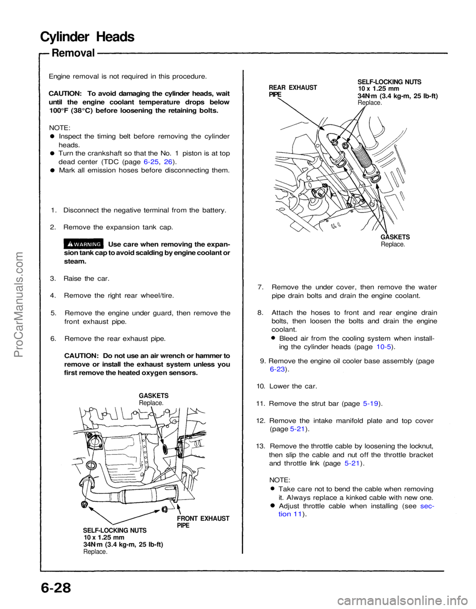
5. Remove the engine under guard, then remove the front exhaust pipe.
6. Remove the rear exhaust pipe.
CAUTION: Do not use an air wrench or hammer to
remove or install the exhaust system unless you
first remove the heated oxygen sensors.
GASKETS
Replace.
FRONT EXHAUST
PIPE
SELF-LOCKING NUTS
10 x
1.25
mm
34N .
m (3.4 kg-m, 25 Ib-ft)
Replace.
REAR EXHAUST
PIPE
SELF-LOCKING NUTS
10 x
1.25
mm
34N .
m (3.4 kg-m, 25 Ib-ft)
Replace.
GASKETS
Replace.
7. Remove the under cover, then remove the water pipe drain bolts and drain the engine coolant.
8. Attach the hoses to front and rear engine drain bolts, then loosen the bolts and drain the engine
coolant.
Bleed air from the cooling system when install-
ing the cylinder heads (page 10-5).
9. Remove the engine oil cooler base assembly (page
6-23).
10. Lower the car.
11. Remove the strut bar (page 5-19).
12. Remove the intake manifold plate and top cover (page 5-21).
13. Remove the throttle cable by loosening the locknut, then slip the cable and nut off the throttle bracketand throttle link (page 5-21).
NOTE:
Take care not to bend the cable when removingit. Always replace a kinked cable with new one.Adjust throttle cable when installing (see sec-
tion 11).ProCarManuals.com
Page 1148 of 1640
Transmission Assembly
Removal
CAUTION: Use fender covers to avoid damaging
painted surfaces.
1. Check and record the rear wheel alignment (see section 18).
2. Disconnect the battery negative (—), and positive (+) cables from the battery.
3. Drain transmission oil. Reinstall the drain plug with a new washer.
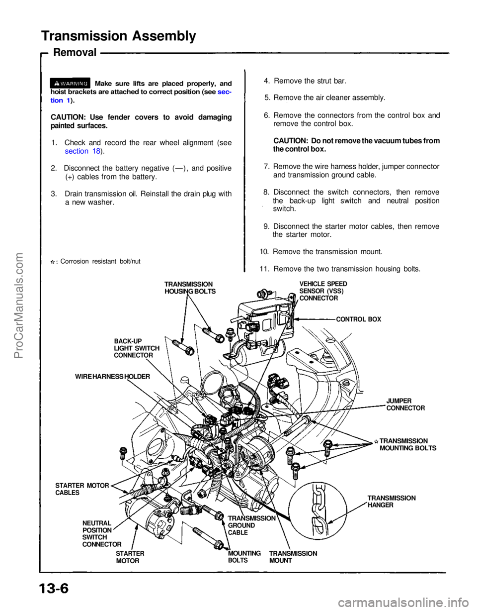
Corrosion resistant bolt/nut 4. Remove the strut bar.
5. Remove the air cleaner assembly.
6. Remove the connectors from the control box and remove the control box.
CAUTION: Do not remove the vacuum tubes from
the control box.
7. Remove the wire harness holder, jumper connector and transmission ground cable.
8. Disconnect the switch connectors, then remove the back-up light switch and neutral positionswitch.
9. Disconnect the starter motor cables, then remove the starter motor.
10. Remove the transmission mount.
11. Remove the two transmission housing bolts.
TRANSMISSION HOUSING BOLTS
BACK-UP
LIGHT SWITCH
CONNECTOR
WIRE HARNESS HOLDER
STARTER MOTOR
CABLES
NEUTRAL
POSITION
SWITCH
CONNECTOR
STARTER
MOTOR
TRANSMISSION
GROUND
CABLE
TRANSMISSION
MOUNT
MOUNTING
BOLTS
TRANSMISSION
HANGER
TRANSMISSION
MOUNTING BOLTS
JUMPER
CONNECTOR
VEHICLE SPEED
SENSOR (VSS)
CONNECTOR
CONTROL BOX
Make sure lifts are placed properly, and
hoist brackets are attached to correct position (see sec-
tion 1).ProCarManuals.com
Page 1149 of 1640
12. Remove the parking brake cable holders from the rear beam rod.
13. Remove the rear beam rod.
14. Remove the front exhaust pipe A.
Corrosion resistant bolt/nut
EXHAUST
PIPE ASELF-LOCKING NUT
Replace.
GASKET
Replace.
GASKET
Replace.
REAR BEAM ROD
1 5. Remove the parking brake cable holder and the wheel sensor wire clamp. 16. Remove the bolt and separate the toe control arm from the side beam (see section 18).
17. Remove the damper fork bolt (see section 18). 18. Remove the bolts and separate the lower control arm from the side beam (see section 18).
19. Pry the driveshaft out of the differential. Pull and remove it. SELF-LOCKING NUT
Replace.
PARKING BRAKE
CABLE HOLDERS
PARKING BRAKE
CABLE HOLDER
FLANGE BOLT
SIDE BEAM TOE CONTROL ARM
SELF-LOCKING NUT Replace. SELF-LOCKING NUT
Replace.
WHEEL SENSOR
WIRE CLAMP
DAMPER FORK BOLT
ADJUSTING
CAM
DRIVESHAFT
ADJUSTING BOLT SELF-LOCKING NUT
Replace.
LOWER CONTROL
ARM
(cont'd)
Corrosion resistant bolt/nutProCarManuals.com
Page 1150 of 1640
Transmission Assembly
Removal (cont'd)
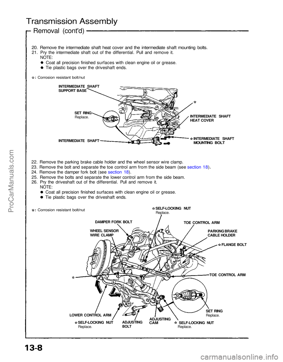
20. Remove the intermediate shaft heat cover and the intermediate shaft mounting bolts.
21. Pry the intermediate shaft out of the differential. Pull and remove it.
NOTE:
Coat all precision finished surfaces with clean engine oil or grease.
Tie plastic bags over the driveshaft ends.
Corrosion resistant bolt/nut
INTERMEDIATE SHAFT
SUPPORT BASE
SET RINGReplace.
INTERMEDIATE SHAFT
22. Remove the parking brake cable holder and the wheel sensor wire clamp.
23. Remove the bolt and separate the toe control arm from the side beam (see section 18).
24. Remove the damper fork bolt (see section 18). 25. Remove the bolts and separate the lower control arm from the side beam.
26. Pry the driveshaft out of the differential. Pull and remove it.
NOTE:
Coat all precision finished surfaces with clean engine oil or grease.
Tie plastic bags over the driveshaft ends.
Corrosion resistant bolt/nut
DAMPER FORK BOLT
WHEEL SENSOR WIRE CLAMP
LOWER CONTROL ARM SELF-LOCKING NUTReplace. ADJUSTING
BOLT
ADJUSTING
CAM
SELF-LOCKING NUT
Replace.SET RING
Replace.TOE CONTROL ARM
PARKING BRAKE
CABLE HOLDER
FLANGE BOLT
TOE CONTROL ARM
SELF-LOCKING NUT
Replace. INTERMEDIATE SHAFT
MOUNTING BOLT
INTERMEDIATE SHAFT
HEAT COVERProCarManuals.com
Page 1161 of 1640
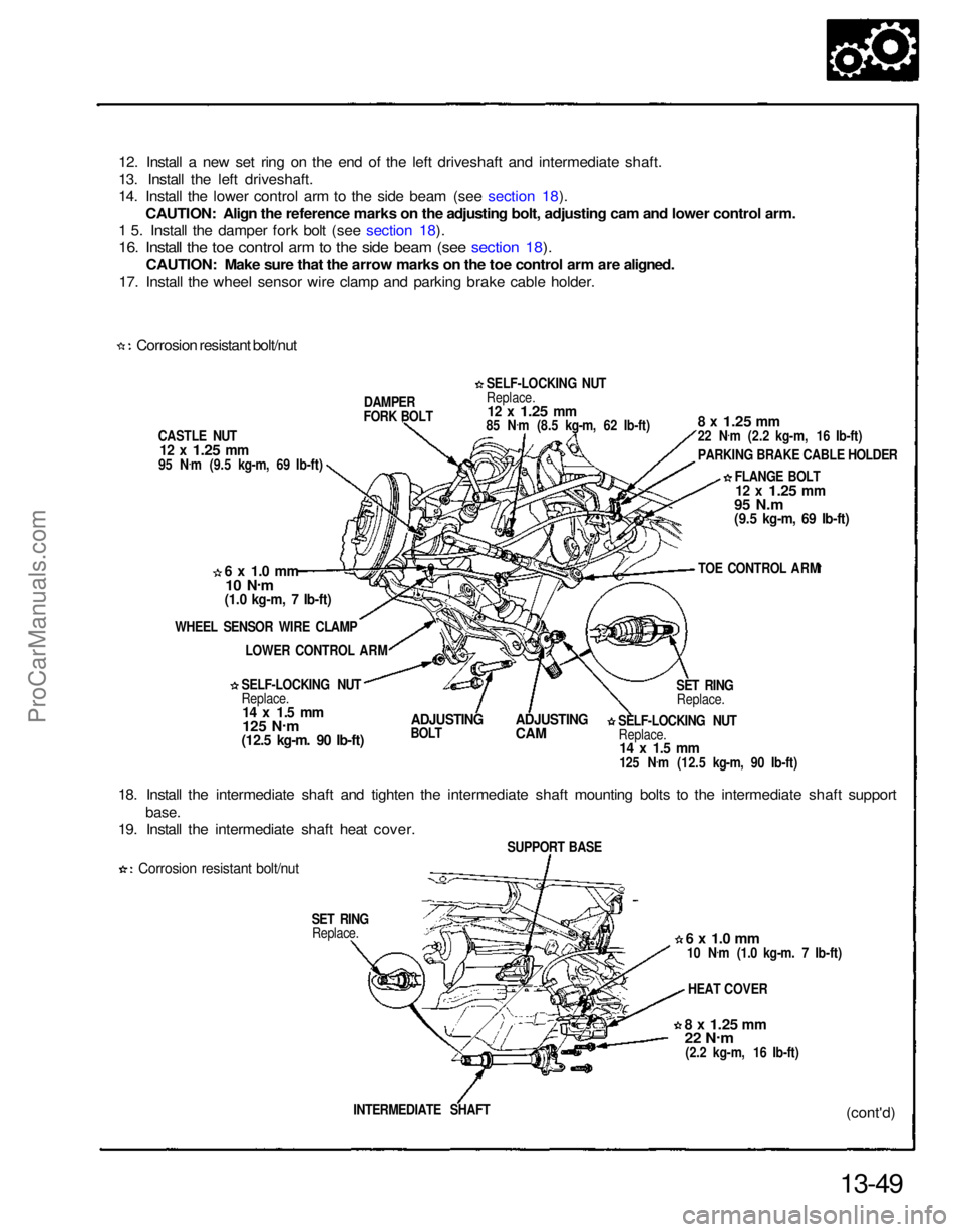
12. Install a new set ring on the end of the left driveshaft and intermediate shaft.
13. Install the left driveshaft.
14. Install the lower control arm to the side beam (see section 18).
CAUTION: Align the reference marks on the adjusting bolt, adjusting cam and lower control arm.
1 5. Install the damper fork bolt (see section 18).
16. Install the toe control arm to the side beam (see section 18).
CAUTION: Make sure that the arrow marks on the toe control arm are aligned.
17. Install the wheel sensor wire clamp and parking brake cable holder.
Corrosion resistant bolt/nut
CASTLE NUT
12 x
1.25
mm
95 N .
m (9.5 kg-m, 69 Ib-ft) DAMPER
FORK BOLT
6 x 1.0 mm
10 N .
m
(1.0 kg-m, 7 Ib-ft)
WHEEL SENSOR WIRE CLAMP LOWER CONTROL ARM
SELF-LOCKING NUT
Replace.
14 x 1.5 mm
125 N .
m
(12.5 kg-m. 90 Ib-ft)
ADJUSTING
BOLT
ADJUSTING
CAM
18. Install the intermediate shaft and tighten the intermediate shaft mounting bolts to the intermediate shaft support
base.
19. Install the intermediate shaft heat cover.
Corrosion resistant bolt/nut
SET RINGReplace.
13-49(cont'd)
INTERMEDIATE SHAFT
8 x
1.25
mm
22 N
.
m
(2.2 kg-m, 16 Ib-ft) HEAT COVER
6 x 1.0 mm
10 N .
m (1.0 kg-m. 7 Ib-ft)
SUPPORT BASE SELF-LOCKING NUT
Replace.
14 x 1.5 mm
125 N .
m (12.5 kg-m, 90 Ib-ft) SET RING
Replace. TOE CONTROL ARM
FLANGE BOLT
12 x
1.25
mm
95 N.m
(9.5 kg-m, 69 Ib-ft)
8 x
1.25
mm
22 N
.
m (2.2 kg-m, 16 Ib-ft)
PARKING BRAKE CABLE HOLDER
SELF-LOCKING NUT
Replace.
12 x
1.25
mm
85 N .
m (8.5 kg-m, 62 Ib-ft)ProCarManuals.com
Page 1231 of 1640
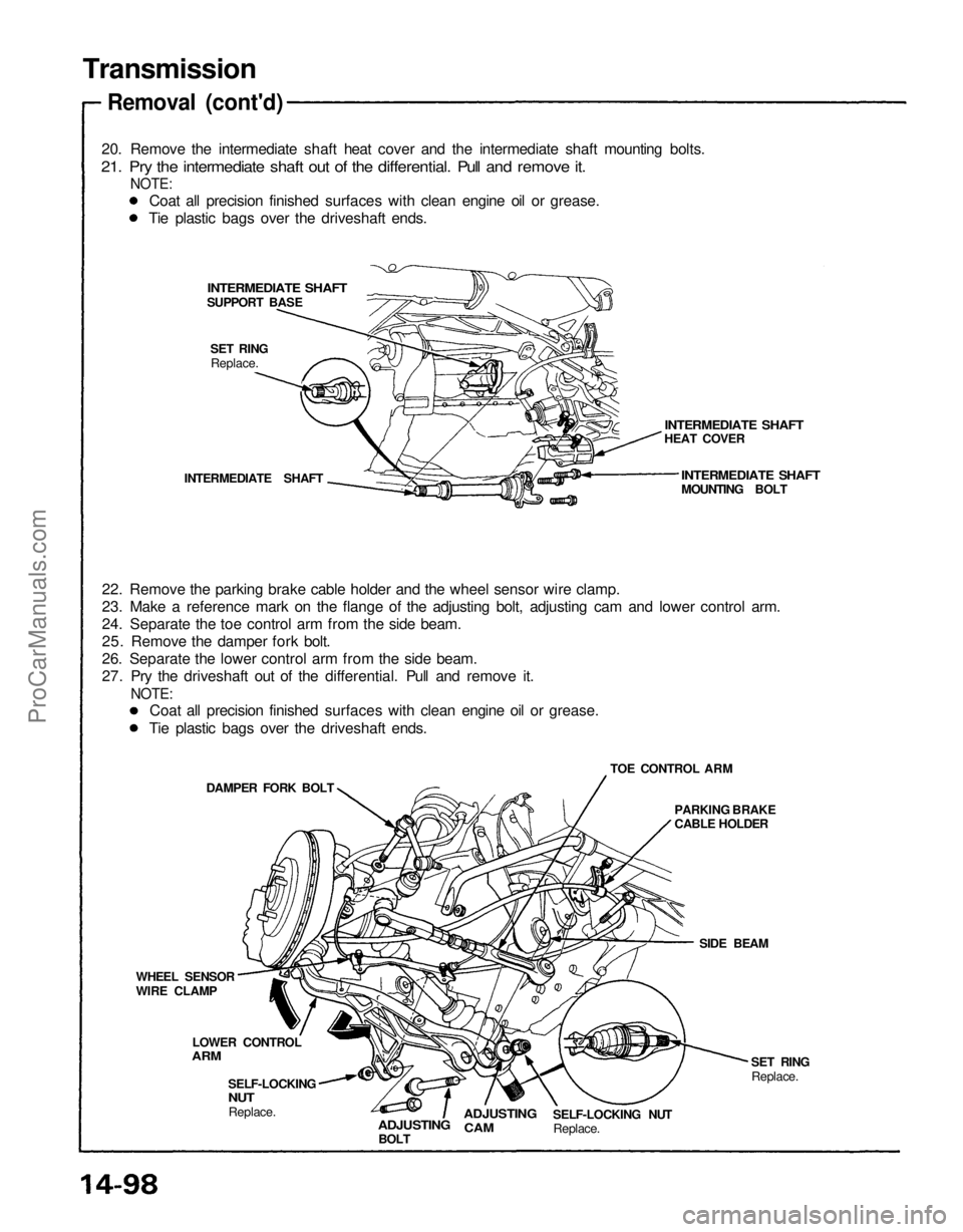
Transmission
Removal (cont'd)
20. Remove the intermediate shaft heat cover and the intermediate shaft mounting bolts.
21. Pry the intermediate shaft out of the differential. Pull and remove it.
NOTE:
INTERMEDIATE SHAFT
INTERMEDIATE SHAFT
HEAT COVER
INTERMEDIATE SHAFT
MOUNTING BOLT
SET RING
Replace.
INTERMEDIATE SHAFT
22. Remove the parking brake cable holder and the wheel sensor wire clamp.
23. Make a reference mark on the flange of the adjusting bolt, adjusting cam and lower control arm.
24. Separate the toe control arm from the side beam.
25. Remove the damper fork bolt.
26. Separate the lower control arm from the side beam.
27. Pry the driveshaft out of the differential. Pull and remove it.
NOTE:
TOE CONTROL ARM
DAMPER FORK BOLT
PARKING BRAKE
CABLE HOLDER
SIDE BEAM
SET RING
Replace.
SELF-LOCKING NUT
Replace.
ADJUSTING
CAM
ADJUSTING
BOLT
SELF-LOCKING
NUT
Replace.
LOWER CONTROL
ARM
WHEEL SENSOR
WIRE CLAMP
SUPPORT BASE
Coat all precision finished surfaces with clean engine oil or grease.
Tie plastic bags over the driveshaft ends.
Coat all precision finished surfaces with clean engine oil or grease.
Tie plastic bags over the driveshaft ends.ProCarManuals.com
Page 1287 of 1640
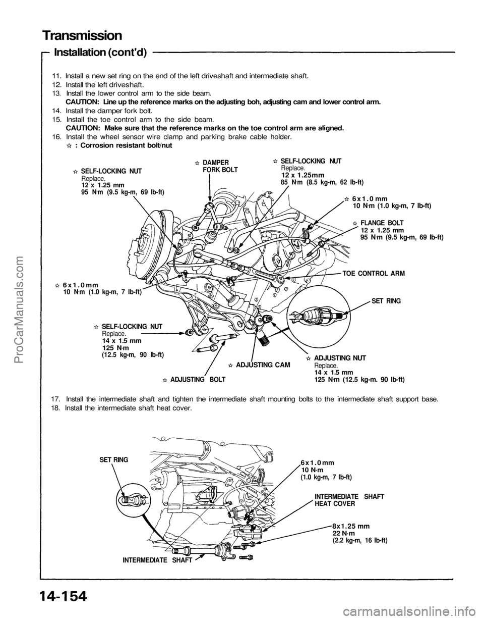
Transmission
Installation (cont'd)
11. Install a new set ring on the end of the left driveshaft and intermediate shaft.
12. Install the left driveshaft.
13. Install the lower control arm to the side beam. CAUTION: Line up the reference marks on the adjusting boh, adjusting cam and lower control arm.
14. Install the damper fork bolt.
15. Install the toe control arm to the side beam. CAUTION: Make sure that the reference marks on the toe control arm are aligned.
16. Install the wheel sensor wire clamp and parking brake cable holder.
SELF-LOCKING NUTReplace.
12 x
1.25
mm
95 N .
m (9.5 kg-m, 69 Ib-ft) DAMPER
FORK BOLT
SELF-LOCKING NUT
Replace.
12 x 1.25mm
85 N .
m (8.5 kg-m, 62 Ib-ft)
6x1.0
mm
10 N .
m (1.0 kg-m, 7 Ib-ft)
FLANGE BOLT
12 x
1.25
mm
95 N .
m (9.5 kg-m, 69 Ib-ft)
TOE CONTROL ARM SET RING
6x1.0
mm
Replace. SELF-LOCKING NUT
ADJUSTING NUT
Replace.
14 x 1.5 mm
125 N .
m (12.5 kg-m. 90 Ib-ft)
ADJUSTING CAM
ADJUSTING BOLT
17. Install the intermediate shaft and tighten the intermediate shaft mounting bolts to the intermediate shaft support base.
18. Install the intermediate shaft heat cover.
6x1.0
mm
10 N·m
(1.0 kg-m, 7 Ib-ft)
INTERMEDIATE SHAFT
HEAT COVER
8x1.25 mm
22 N·m
(2.2 kg-m, 16 Ib-ft)
INTERMEDIATE SHAFT
SET RING
Corrosion resistant bolt/nut
10 N .
m (1.0 kg-m, 7 Ib-ft)
14 x 1.5 mm
125 N .
m
(12.5 kg-m, 90 Ib-ft)ProCarManuals.com
Page 1295 of 1640
System Description
Steering Column
The NSX has a tilt/telescopic steering column. The tilt/telescopic mechanism makes it possible to adjust the steering
wheel in fore and aft, and up and down directions.
Tilt Mechanism
There is a joint on the upper steering shaft, and the portion of the column between the steering wheel and this joint
is
adjustable
up and
down. When
the
tilt
lever
is
operated,
the
lock
gears
are
detached from
the
column
gear
to
release
the
lock.
The
column
moves
upward
or
downward
on two
pivot bolts. When
the
tilt
lever
is
returned
to a
fixed position
after selecting the steering wheel height, the lock gear is engaged with the column gear to secure the column.
PIVOT
BOLT
TILT LEVER
COLUMN
GEAR
PIVOT
BOLT
LOCK GEAR
TILT LEVER
(cont'd)
JOINTProCarManuals.com