Page 99 of 1640

Cylinder Heads
Removal
Engine removal is not required for this procedure. Make sure jacks and safety stands are
placed properly and hoist brackets ere attached to cor- rect positions on the engine.
CAUTION: Use a fender cover (special tool) to avoid damaging
painted surfaces. Unplug the wiring connectors carefully while holding
the connector portion to avoid damage.
To avoid damaging the cylinder heads, wait until the
engine coolant temperature drops below 100°F
(38°C) before loosening the retaining bolts. Do not open the engine cover when the roof panel is
stored (NSX-T open top).
NOTE:
Unspecified items are common.
Mark all wiring and hoses to avoid misconnection.
Also, be sure that they do not contact other wiring or
hoses or interfere with other parts.
Inspect the timing belt before removing the cylinder
head.
Turn the crankshaft pulley SO that the No. 1 piston is at top dead center (see page 6-19 ('91-'93) or ('94-'96)).
1. Disconnect the negative terminal from the battery.
2. Remove the expansion tank cap. Use care when removing the expan-
sion tank cap to avoid scalding by engine coolant
or steam.
3. Raise the car, then remove the right rear wheel/tire.
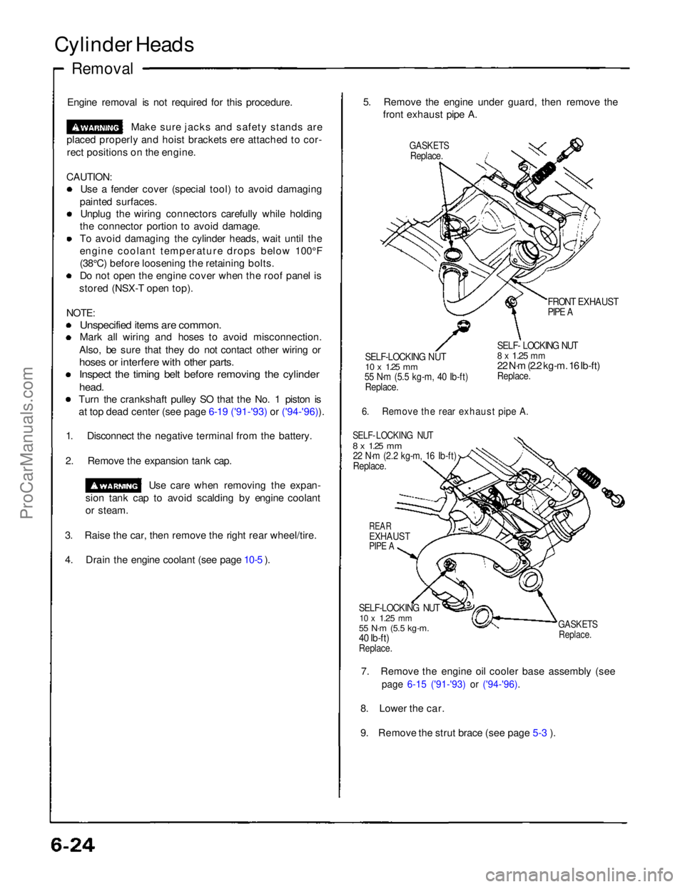
4. Drain the engine coolant (see page 10-5 ). 5. Remove the engine under guard, then remove the
front exhaust pipe A.
GASKETS
Replace.
FRONT EXHAUST
PIPE A
SELF-LOCKING NUT
10 x
1.25
mm
55 N·m (5.5 kg-m, 40 Ib-ft)
Replace.
SELF- LOCKING NUT
8 x
1.25
mm
22 N·m (2.2 kg-m. 16 Ib-ft)
Replace.
6. Remove the rear exhaust pipe A.
SELF- LOCKING NUT
8 x
1.25
mm
22 N·m (2.2 kg-m, 16 Ib-ft)
Replace.
REAR
EXHAUST
PIPE A
SELF-LOCKING NUT
10 x
1.25
mm
55 N·m (5.5 kg-m.
40 Ib-ft)
Replace.
GASKETS
Replace.
7. Remove the engine oil cooler base assembly (see
page 6-15 ('91-'93) or ('94-'96).
8. Lower the car.
9. Remove the strut brace (see page 5-3 ).ProCarManuals.com
Page 675 of 1640
Opener/Latch/Opener cable/Hook stop/Roof stop
bracket removal:
1. Open the engine cover. Remove the screws, then
remove the support rod bracket. Remove the push
nuts, then remove the engine cover insulator.
ENGINE
COVER
SUPPORT ROD
BRACKET
ENGINE COVER
INSULATOR
2. Remove the roof cover latch, roof cover opener and
roof cover opener cable from the engine cover.
NOTE: Take care not to bend the roof cover opener
cable.
6 x 1.0 mm
10 N-m
(1.0 kg-m,
7.2 Ib-ft)
ROOF COVER
OPENER
ENGINE COVER
SHIMS
Thickness: 1.0 mm
(0.039 in)
ROOF COVER
LATCH
ROOF COVER
OPENER CABLE
ROOF COVER
OPENER
R
OOF COVER
OPENER CABLE
KNOB
ROOF COVER
LATCH
ROOF COVER
OPENER CABLEProCarManuals.com
Page 676 of 1640
Engine Cover/Roo f Cove r
Replacemen t
3. Remov e th e roo f sto p bracket s an d hoo k stop s fro m
th e engin e cover .
LEFT ROO F STO P BRACKET /
ROO F HOLDE R SWITC H RIGH
T
ROO F STO PBRACKE T
ENGINECOVERHOOK STOP S
CONNECTO R
LEF T ROO F
STO P BRACKE T
This scre w o n th e righ troof sto p bracke t i sscre w A .
Nu t locations , 4
6 x 1. 0 m m10 N- m (1. 0 kg-m ,7.2 Ib-ft ) HOO
K STO P
4. Installatio n is th e revers e o f th e remova l procedure .
NOTE:
• Mak e sur e th e roo f cove r open s properl y an d
lock s securely .
• Mak e sur e th e roo f fit s o n th e engin e cove r
securely .
HOOK
STO P
ROO
F HOLDE R
SWITCHENGINECOVERROOF
ROO F SIDE .
HOO K
ROOF
ProCarManuals.com
Page 730 of 1640

Troubleshooting
Tips and Precautions
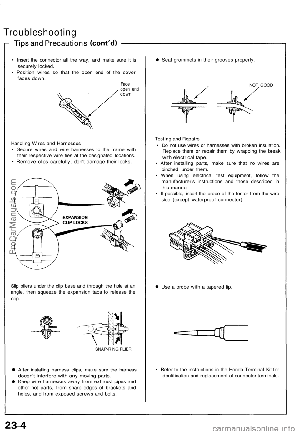
• Insert the connector all the way, and make sure it is
securely locked.
• Position wires so that the open end of the cover
faces down.
Face
open end
down
Handling Wires and Harnesses
• Secure wires and wire harnesses to the frame with
their respective wire ties at the designated locations.
• Remove clips carefully; don't damage their locks.
Slip pliers under the clip base and through the hole at an
angle, then squeeze the expansion tabs to release the
clip.
SNAP-RING PLIER
After installing harness clips, make sure the harness
doesn't interfere with any moving parts.
Keep wire harnesses away from exhaust pipes and
other hot parts, from sharp edges of brackets and
holes, and from exposed screws and bolts.
Seat grommets in their grooves properly.
NOT GOOD
Testing and Repairs
• Do not use wires or harnesses with broken insulation.
Replace them or repair them by wrapping the break
with electrical tape.
• After installing parts, make sure that no wires are
pinched under them.
• When using electrical test equipment, follow the
manufacturer's instructions and those described in
this manual.
• If possible, insert the probe of the tester from the wire
side (except waterproof connector).
Use a probe with a tapered tip.
• Refer to the instructions in the Honda Terminal Kit for
identification and replacement of connector terminals.ProCarManuals.com