Page 27 of 1640
Lubrication Points
For the details of lubrication points and types of lubricants to be applied, refer to the Illustrated Index and various work
procedures (such as Assembly/Reassembly, Replacement, Overhaul, Installation, etc.) contained in each section.
*1: If Honda MTF is not available, you may use an API service SG or SH-rated motor oil with a viscosity of SAE
10 W-30 or 10 W-40 temporarily. Motor oil can cause increased transmission wear and higher shifting effort, so you
should have the transmission drained and refilled with Honda MTF as soon as possible. The transmission should be
drained and refilled with new fluid according to the time and distance recommendations in the maintenance schedule.ProCarManuals.com
Page 72 of 1640
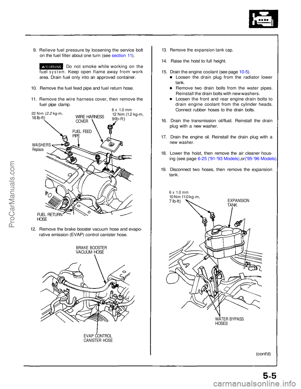
9. Relieve fuel pressure by loosening the service bolt
on the fuel filter about one turn (see section 11).
Do not smoke while working on the
fuel
system.
Keep open flame away from work
area. Drain fuel only into an approved container.
10. Remove the fuel feed pipe and fuel return hose.
11. Remove the wire harness cover, then remove the fuel pipe clamp.
22 N·m
(2.2 kg-m,
16 Ib-ft)
WIRE HARNESS
COVER
6 x 1.0 mm
12 N·m
(1.2 kg-m,
9 lb-ft)
FUEL FEED
PIPE
WASHERS
Replace.
FUEL RETURN
HOSE
12. Remove the brake booster vacuum hose and evapo- rative emission (EVAP) control canister hose.
BRAKE BOOSTER
VACUUM HOSE
EVAP CONTROL
CANISTER HOSE
13. Remove the expansion tank cap.
14. Raise the hoist to full height.
15. Drain the engine coolant (see page
10-5).
Loosen the drain plug from the radiator lower
tank. Remove two drain bolls from the water pipes.
Reinstall the drain bolts with new washers.
Loosen the front and rear engine drain bolts to
drain engine coolant from the cylinder heads.
Connect rubber hoses to the drain bolts.
16. Drain the transmission oil/fluid. Reinstall the drain plug with a new washer.
17. Drain the engine oil. Reinstall the drain plug with a
new washer.
18. Lower the hoist, then remove the air cleaner hous-
ing (see page 6-25 ('91-'93 Mode ls),or('95-'96 Models).
19. Disconnect two hoses, then remove the expansion
tank.
6 x 1.0 mm
10 N·m
11.0 kg-m,
7 lb-ft)
EXPANSION
TANK
WATER BYPASS
HOSES
(cont'd)ProCarManuals.com
Page 80 of 1640
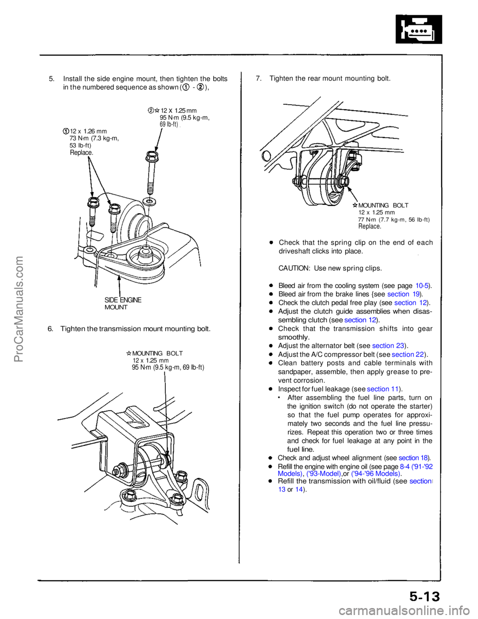
5. Install the side engine mount, then tighten the bolts
in the numbered sequence as shown ( - ),
12 x
1.26
mm
73 N·m
(7.3 kg-m,
53 Ib-ft)
Replace.
12 x
1.25
mm
95 N·m
(9.5 kg-m,
69 Ib-ft)
SIDE ENGINE
MOUNT
6. Tighten the transmission mount mounting bolt.
MOUNTING BOLT
12 x
1.25
mm
95 N·m (9.5 kg-m, 69 Ib-ft)
7. Tighten the rear mount mounting bolt.
MOUNTING BOLT
12 x
1.25
mm
77 N·m (7.7 kg-m, 56 Ib-ft)
Replace.
Check that the spring clip on the end of each
driveshaft clicks into place.
CAUTION: Use new spring clips.
Bleed air from the cooling system (see page 10-5).
Bleed air from the brake lines {see section 19).
Check the clutch pedal free play (see section 12).
Adjust the clutch guide assemblies when disas-
sembling clutch (see section 12).
Check that the transmission shifts into gear
smoothly.
Adjust the alternator belt (see section 23).
Adjust the A/C compressor belt (see section 22).
Clean battery posts and cable terminals with
sandpaper, assemble, then apply grease to pre-
vent corrosion.
Inspect for fuel leakage (see section 11). After assembling the fuel line parts, turn on
the ignition switch (do not operate the starter) so that the fuel pump operates for approxi-
mately two seconds and the fuel line pressu-
rizes. Repeat this operation two or three times
and check for fuel leakage at any point in the
fuel line.
Check and adjust wheel alignment (see section 18).
Refill the engine with engine oil (see page 8-4 ('91-'92
Models), ('93-Model),or ('94-'96 Models).
Refill the transmission with oil/fluid (see section
13 or
14).ProCarManuals.com
Page 91 of 1640
Timing Belt
Removal (cont'd)
7. Remove the breather hose and the air cleaner hous-
in
g
(see page 6-25 ('91-'93) or ('94-'96) )
8. Disconnect the alternator connector and the termi-
nal.
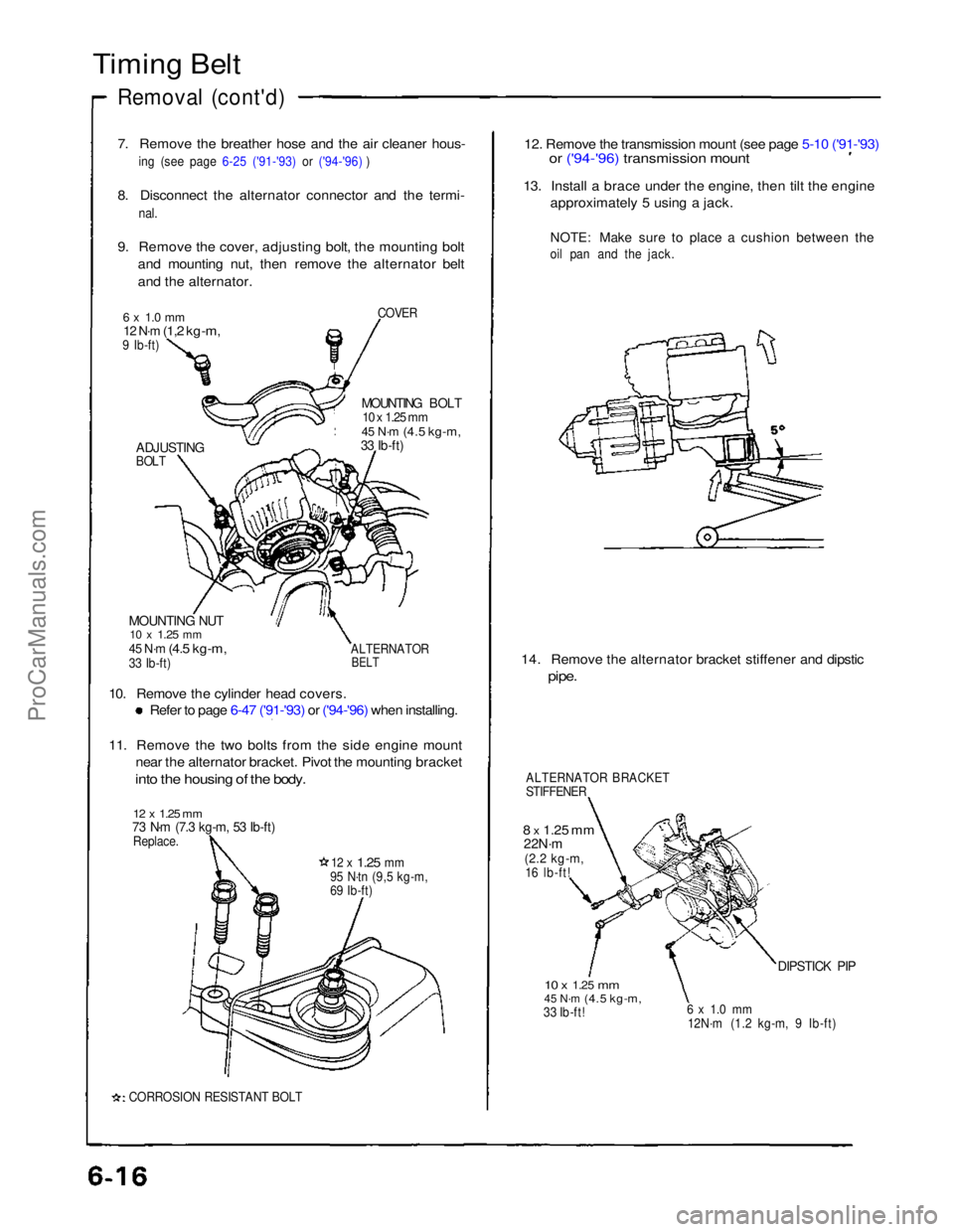
9. Remove the cover, adjusting bolt, the mounting bolt and mounting nut, then remove the alternator belt
and the alternator.
COVER
6 x 1.0 mm
12 N·m
(1,2 kg-m,
9 Ib-ft)
MOUNTING BOLT
10 x 1.25 mm
45 N·m
(4.5 kg-m,
33 Ib-ft)
ADJUSTING
BOLT
MOUNTING NUT
10 x
1.25
mm
45 N·m
(4.5 kg-m,
33 Ib-ft)
ALTERNATOR
BELT
10. Remove the cylinder head covers.
Refer to page 6-47 ('91-'93) or ('94-'96) when installing.
11. Remove the two bolts from the side engine mount
near the alternator bracket. Pivot the mounting bracket
into the housing of the body.
12 x 1.25 mm
73 N·m (7.3 kg-m, 53 Ib-ft)
Replace.
12 x
1.25
mm
95 N·tn (9,5 kg-m,
69 Ib-ft)
CORROSION RESISTANT BOLT
12. Remove the transmission mount (see page 5-10 ('91-'93)
or ('94-'96) transmission mount
13. Install a brace under the engine, then tilt the engine
approximately 5 using a jack.
NOTE: Make sure to place a cushion between the
oil pan and the jack.
14. Remove the alternator bracket stiffener and dipstic
pipe.
ALTERNATOR BRACKET
STIFFENER
8 x
1.25
mm
22N·m
(2.2 kg-m,
16 lb-ft!
10 x
1.25
mm
45 N·m
(4.5 kg-m,
33 Ib-ft!
6 x 1.0 mm
12N·m (1.2 kg-m, 9 Ib-ft)
DIPSTICK PIPProCarManuals.com
Page 304 of 1640
Transmission Assembl y
Removal
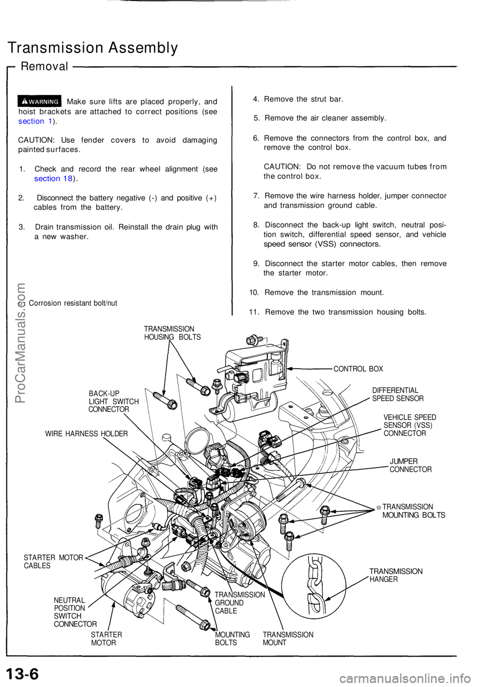
Make sur e lift s ar e place d properly , an d
hois t bracket s ar e attache d t o correc t position s (se e
sectio n 1 ).
CAUTION : Us e fende r cover s t o avoi d damagin g
painte d surfaces .
1 . Chec k an d recor d th e rea r whee l alignmen t (se e
sectio n 18 ).
2 . Disconnec t th e batter y negativ e (- ) an d positiv e (+ )
cable s fro m th e battery .
3 . Drai n transmissio n oil . Reinstal l th e drai n plu g wit h
a ne w washer .
Corrosio n resistan t bolt/nu t
4. Remov e th e stru t bar .
5 . Remov e th e ai r cleane r assembly .
6 . Remov e th e connector s fro m th e contro l box , an d
remov e th e contro l box .
CAUTION : D o no t remov e th e vacuu m tube s fro m
th e contro l box .
7 . Remov e th e wir e harnes s holder , jumpe r connecto r
an d transmissio n ground cable.
8 . Disconnec t th e back-u p ligh t switch , neutra l posi -
tio n switch , differentia l spee d sensor , an d vehicl e
speed senso r (VSS ) connectors .
9. Disconnec t th e starte r moto r cables , the n remov e
th e starte r motor .
10 . Remov e th e transmissio n mount .
11 . Remov e th e tw o transmissio n housin g bolts .
TRANSMISSIO N
HOUSIN G BOLT S
CONTROL BO X
BACK-U PLIGHT SWITC H
CONNECTO R
WIR E HARNES S HOLDE R
STARTER MOTOR
CABLES
NEUTRA L
POSITIO N
SWITCHCONNECTO R
DIFFERENTIA L
SPEE D SENSO R
VEHICL E SPEE D
SENSO R (VSS )
CONNECTO R
JUMPERCONNECTO R
TRANSMISSIO N
MOUNTING BOLT S
TRANSMISSIO NHANGER
STARTE RMOTOR MOUNTIN
G TRANSMISSIO N
BOLT S MOUN T
TRANSMISSIO
N
GROUN D
CABLE
ProCarManuals.com
Page 306 of 1640
Transmission Assembly
Removal
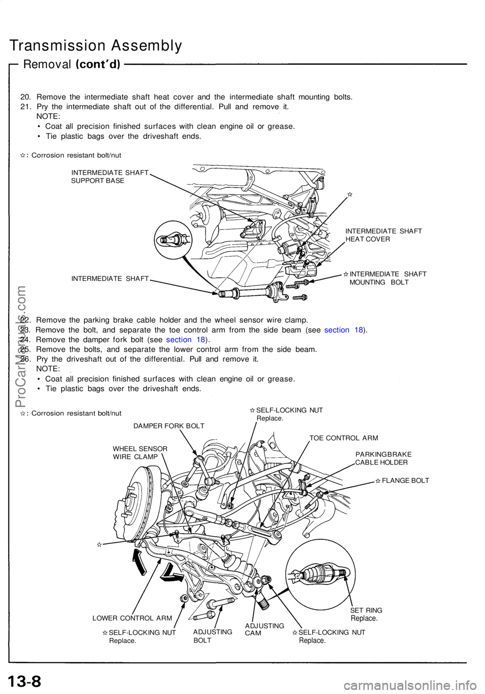
20. Remove the intermediate shaft heat cover and the intermediate shaft mounting bolts.
21. Pry the intermediate shaft out of the differential. Pull and remove it. NOTE:
• Coat all precision finished surfaces with clean engine oil or grease.
• Tie plastic bags over the driveshaft ends.
Corrosion resistant bolt/nut
INTERMEDIATE SHAFT
SUPPORT BASE
INTERMEDIATE SHAFT INTERMEDIATE SHAFT
HEAT COVER
INTERMEDIATE SHAFT
MOUNTING BOLT
22. Remove the parking brake cable holder and the wheel sensor wire clamp.
23. Remove the bolt, and separate the toe control arm from the side beam (see section 18).
24. Remove the damper fork bolt (see section 18).
25. Remove the bolts, and separate the lower control arm from the side beam. 26. Pry the driveshaft out of the differential. Pull and remove it. NOTE:
• Coat all precision finished surfaces with clean engine oil or grease.
• Tie plastic bags over the driveshaft ends.
Corrosion resistant bolt/nut
DAMPER FORK BOLT SELF-LOCKING NUT
Replace.
TOE CONTROL ARM
WHEEL SENSOR WIRE CLAMP PARKING BRAKE
CABLE HOLDER
FLANGE BOLT
LOWER CONTROL ARM SELF-LOCKING NUTReplace. ADJUSTING
BOLT
ADJUSTING
CAM
SELF-LOCKING NUT
Replace.
SET RING
Replace.ProCarManuals.com
Page 310 of 1640
Transmission Housing
Removal
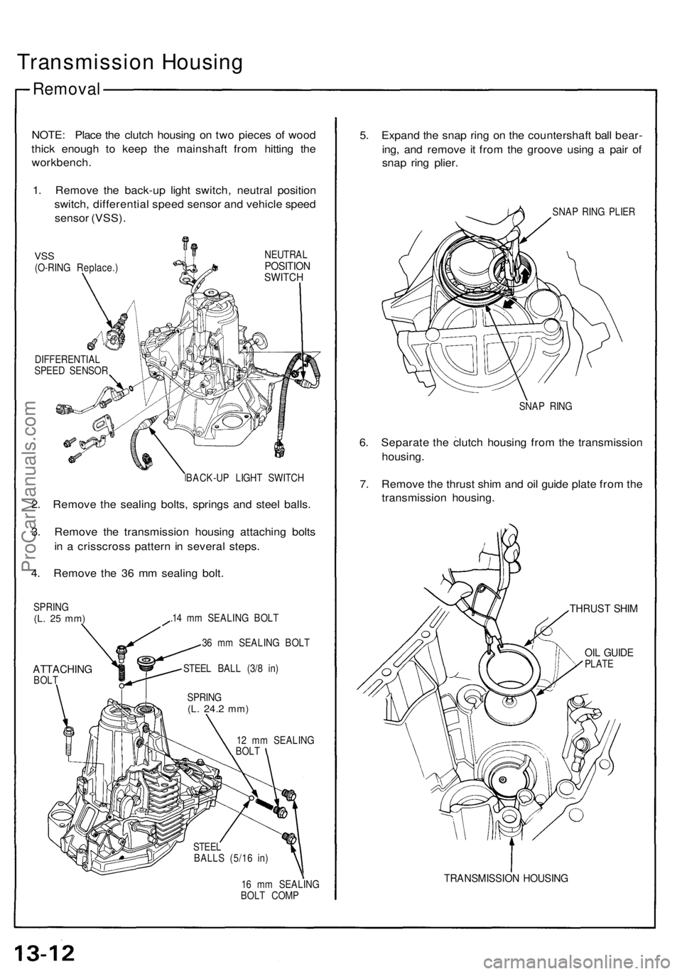
NOTE: Place the clutch housing on two pieces of wood
thick enough to keep the mainshaft from hitting the
workbench.
1. Remove the back-up light switch, neutral position
switch, differential speed sensor and vehicle speed
sensor (VSS).
VSS
(O-RING Replace.)
NEUTRAL
POSITION
SWITCH
DIFFERENTIAL
SPEED SENSOR
BACK-UP LIGHT SWITCH
2. Remove the sealing bolts, springs and steel balls.
3. Remove the transmission housing attaching bolts
in a crisscross pattern in several steps.
4. Remove the 36 mm sealing bolt.
SPRING
(L. 25 mm)
ATTACHING
BOLT
.14 mm SEALING BOLT
36 mm SEALING BOLT
STEEL BALL (3/8 in)
12 mm SEALING
BOLT
16 mm SEALING
BOLT COMP
5. Expand the snap ring on the countershaft ball bear-
ing, and remove it from the groove using a pair of
snap ring plier.
SNAP RING PLIER
SNAP RING
6. Separate the clutch housing from the transmission
housing.
7. Remove the thrust shim and oil guide plate from the
transmission housing.
THRUST SHIM
OIL GUIDE
PLATE
TRANSMISSION HOUSING
SPRING
(L.
24.2
mm)
STEEL
BALLS (5/16 in)ProCarManuals.com
Page 318 of 1640
Shift Lever,
Select Lever
Removal
1. Remove the shift spring set plate and shift detent
spring from the transmission housing.
TRANSMISSION
HOUSING
SHIFT SPRING
SET PLATE
SHIFT DETENT
SPRING
2. Remove the bolt and spring washer.
3. Pull out the shift lever, then remove the shift arm.
SPRING WASHER
SHIFT ARM
SHIFT LEVER
OIL SEAL
Replace.ProCarManuals.com