Page 5 of 1640
Warning/Caution Labe l Location s
SRS CAUTIO N LABELS : Refe r t o pag e 1- 6
FROZE NBATTER Y CAUTIO N
AI R CONDITIONIN G
R-134 a CAUTIO N
(U.S.A. only )
ENGIN E COOLAN TCAUTION • PRECAUTIO N
ABS CAUTIO N
ABS an d BRAK EFLUID CAUTIO N
RETRACTABL EHEADLIGHT CAUTIO N
EMISSION CONTRO L
INFORMATIO N an d
VACUU M HOS E
ROUTIN G DIAGRA M
BATTERYCAUTION
RADIATO R BLEE DPLUG CAUTIO N
EXPANSIO NTANK CA PCAUTIO N
SPAR K PLU G
CAUTIO N
TIRE INFORMATIO N
ProCarManuals.com
Page 73 of 1640
Engine Removal/Installation
Removal
20. Disconnect the engine wire harness connectors.
21. Remove the battery cable from the main fuse box.
ENGINE WIRE
HARNESS CONNECTORS
BATTERY
CABLE
6 x 1.0 mm
10 N-m
(1.0 kg-m,
7 Ib-ft)
22. Disconnect the throttle body 6P connector, and
remove the ground cable and starter cable.
STARTER CABLE
THROTTLE BODY
6P CONNECTOR
GROUND CABLE
CORROSION RESISTANT BOLT
23. Disconnect the two connectors from the emission
control box, then remove the control box.
• Do not disconnect the vacuum hoses.
6 x 1.0 mm
10 N-m (1.0 kg-m, 7 Ib-ft)
CONNECTORS
CONTROL BOX
24. Remove the radiator hoses and heater hose.
HEATER HOSE
RADIATOR
HOSESProCarManuals.com
Page 80 of 1640

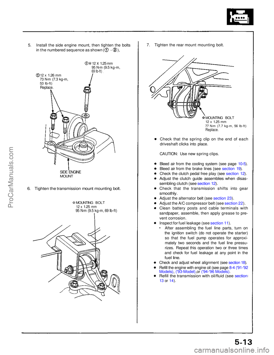
5. Install the side engine mount, then tighten the bolts
in the numbered sequence as shown ( - ),
12 x
1.26
mm
73 N·m
(7.3 kg-m,
53 Ib-ft)
Replace.
12 x
1.25
mm
95 N·m
(9.5 kg-m,
69 Ib-ft)
SIDE ENGINE
MOUNT
6. Tighten the transmission mount mounting bolt.
MOUNTING BOLT
12 x
1.25
mm
95 N·m (9.5 kg-m, 69 Ib-ft)
7. Tighten the rear mount mounting bolt.
MOUNTING BOLT
12 x
1.25
mm
77 N·m (7.7 kg-m, 56 Ib-ft)
Replace.
Check that the spring clip on the end of each
driveshaft clicks into place.
CAUTION: Use new spring clips.
Bleed air from the cooling system (see page 10-5).
Bleed air from the brake lines {see section 19).
Check the clutch pedal free play (see section 12).
Adjust the clutch guide assemblies when disas-
sembling clutch (see section 12).
Check that the transmission shifts into gear
smoothly.
Adjust the alternator belt (see section 23).
Adjust the A/C compressor belt (see section 22).
Clean battery posts and cable terminals with
sandpaper, assemble, then apply grease to pre-
vent corrosion.
Inspect for fuel leakage (see section 11). After assembling the fuel line parts, turn on
the ignition switch (do not operate the starter) so that the fuel pump operates for approxi-
mately two seconds and the fuel line pressu-
rizes. Repeat this operation two or three times
and check for fuel leakage at any point in the
fuel line.
Check and adjust wheel alignment (see section 18).
Refill the engine with engine oil (see page 8-4 ('91-'92
Models), ('93-Model),or ('94-'96 Models).
Refill the transmission with oil/fluid (see section
13 or
14).ProCarManuals.com
Page 90 of 1640

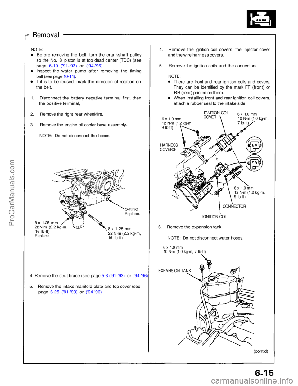
Removal
NOTE:
Before removing the belt, turn the crankshaft pulley
so the No. 8 piston is at top dead center (TDC) (see
page 6-19 ('91-'93) or ('94-'96)
Inspect the water pump after removing the timing
belt (see page 10-11).
If it is to be reused, mark the direction of rotation on
the belt.
1. Disconnect the battery negative terminal first, then the positive terminal,
2. Remove the right rear wheel/tire.
3. Remove the engine oil cooler base assembly- NOTE: Do not disconnect the hoses.
O-RING
Replace.
8 x
1.25
mm
22 N·m
(2.2 kg-m,
16 Ib-ft)
8 x
1.25
mm
22 N·m
(2.2 kg-m,
16 Ib-ft)
Replace.
4. Remove the strut brace (see page 5-3 ('91-'93) or ('94-'96)
5. Remove the intake manifold plate and top cover (see
page 6-25 ('91-'93) or ('94-'96)
4. Remove the ignition coil covers, the injector cover
and the wire harness covers.
5. Remove the ignition coils and the connectors.
NOTE:
There are front and rear ignition coils and covers.
They can be identified by the mark FF (front) orRR (rear) printed on them.
When installing front and rear ignition coil covers,
attach a rubber seal to the intake side.
6 x 1.0 mm
12 N·m
(1.2 kg-m,
9 Ib-ft)
IGNITION COIL
COVER
6 x 1.0 mm
10 N·m
(1.0 kg-m,
7 Ib-ft)
HARNESS
COVERS
6 x 1.0 mm
12 N·m
(1.2 kg-m,
9 Ib-ft)
CONNECTOR
IGNITION COIL
6. Remove the expansion tank.
NOTE: Do not disconnect water hoses.
6 x 1.0 mm
10 N·m (1.0 kg-m, 7 Ib-ft)
EXPANSION TANK
(cont'd)ProCarManuals.com
Page 99 of 1640

Cylinder Heads
Removal
Engine removal is not required for this procedure. Make sure jacks and safety stands are
placed properly and hoist brackets ere attached to cor- rect positions on the engine.
CAUTION: Use a fender cover (special tool) to avoid damaging
painted surfaces. Unplug the wiring connectors carefully while holding
the connector portion to avoid damage.
To avoid damaging the cylinder heads, wait until the
engine coolant temperature drops below 100°F
(38°C) before loosening the retaining bolts. Do not open the engine cover when the roof panel is
stored (NSX-T open top).
NOTE:
Unspecified items are common.
Mark all wiring and hoses to avoid misconnection.
Also, be sure that they do not contact other wiring or
hoses or interfere with other parts.
Inspect the timing belt before removing the cylinder
head.
Turn the crankshaft pulley SO that the No. 1 piston is at top dead center (see page 6-19 ('91-'93) or ('94-'96)).
1. Disconnect the negative terminal from the battery.
2. Remove the expansion tank cap. Use care when removing the expan-
sion tank cap to avoid scalding by engine coolant
or steam.
3. Raise the car, then remove the right rear wheel/tire.
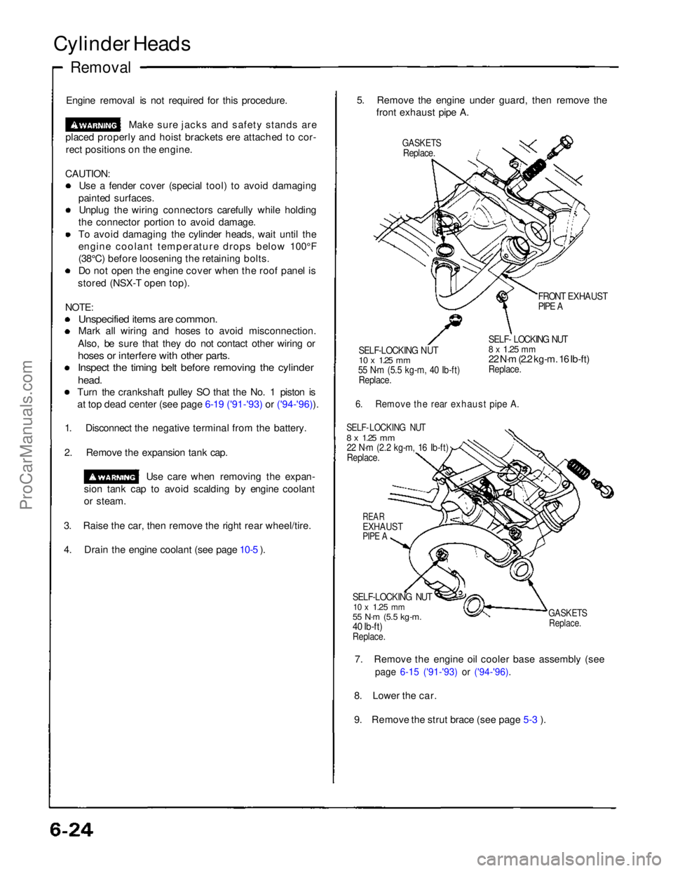
4. Drain the engine coolant (see page 10-5 ). 5. Remove the engine under guard, then remove the
front exhaust pipe A.
GASKETS
Replace.
FRONT EXHAUST
PIPE A
SELF-LOCKING NUT
10 x
1.25
mm
55 N·m (5.5 kg-m, 40 Ib-ft)
Replace.
SELF- LOCKING NUT
8 x
1.25
mm
22 N·m (2.2 kg-m. 16 Ib-ft)
Replace.
6. Remove the rear exhaust pipe A.
SELF- LOCKING NUT
8 x
1.25
mm
22 N·m (2.2 kg-m, 16 Ib-ft)
Replace.
REAR
EXHAUST
PIPE A
SELF-LOCKING NUT
10 x
1.25
mm
55 N·m (5.5 kg-m.
40 Ib-ft)
Replace.
GASKETS
Replace.
7. Remove the engine oil cooler base assembly (see
page 6-15 ('91-'93) or ('94-'96).
8. Lower the car.
9. Remove the strut brace (see page 5-3 ).ProCarManuals.com
Page 215 of 1640
Troubleshooting
Engine Control Module Terminal Arrangement
ECM CONNECTOR A (26P)
ECM CONNECTOR A (26P)
TERMINAL SIDE OF MALE TERMINALS
NOTE: Standard battery voltage is 12 V.ProCarManuals.com
Page 216 of 1640
ECM CONNECTOR B (16P)
ECM CONNECTOR B (16P)
TERMINAL SIDE OF MALE TERMINALS
NOTE: Standard battery voltage is 12 V.
*: M/TProCarManuals.com
Page 217 of 1640
Troubleshooting
Engine Control Module Terminal Arrangement (cont'd)
ECM CONNECTOR C (12P)
TERMINAL SIDE OF MALE TERMINALS
ECM CONNECTOR C (12P)
NOTE: Standard battery voltage is 12 V.
*: M/TProCarManuals.com