Page 563 of 1640
Types and Materials of Exterior Resin Parts
NOTE: A standard symbol is stamped on the underside of each resin part to show the type of material used.
Example:
HONDA
>PP<
NO.
Part Name
Headlight lid
Front bumper
Front and rear skirts
Mirror
Side sill panel
Trunk ltd spoiler
Rear bumper
Fuel filler lid
Washer Tank
Replacement
see section 23
see page 20-58('93-'96) ,47('91-'92)
see pages 20-59 ('93-'96),48 ('91-'92),
61('93-'96),50('91-'92)
see page 20-20('93-96) ,19('91-'92)
see page 20-71
see page 20-66('93-'96),55('91-'92)
see page 20-60('93-'96),49('91-'92)
see page 20-68('93-'96),57('91-'92)
see page 20-59('93-'96),48('91-'92)
Material
PA6/PPE-M Polyamide/Polyphenylene ether
PBT-P Polybutylene terephthalate
PP Polypropylene
ABS Acrylonitrite butadiene styrene
PA6/PPE-M Polyamide/Polyphenylene ether
UP-G Polyster unsaturated thermoset
PBT-P Polybutylene terephthalate
PA6/PP-E Polyamide/Polyphenylene ether
PP PolypropyleneProCarManuals.com
Page 564 of 1640
Doors
REAR SASH
Adjustment, see page 20-17('93-'96),16('91-'92)
REAR GLASS
GUIDE
Index
FRONT GLASS
GUIDE
REGULATOR
ASSEMBLY
INNER MOLDING STOPPER
PLATES GLASS
Adjustment, see page 20-14('93-'96),
13('91-'92)
FRONT SASH
Adjustment, see page 20-17('93-'96),
16('91-'92)
POWER MIRROR
INSIDE STABILIZERS OUTER MOLDING
DOOR HINGE
POWER WINDOW
MOTOR
LOCK
CYLINDER
DOOR
Disassembly, see page 20-7
('93-'96),6('91-'92)
Assembly, see page 20-13
('93-'96),12('91-'92)
Adjustment, see page 20-19
('93-'96),18('91-'92)
STRIKER
Adjustment, see page 20-19
('93-'96),18('91-'92)
LOCK ROD
LATCH
ASSEMBLY INNER HANDLE HANDLE CABLE
TRIM PLATE POWER DOOR
LOCK SWITCHDOOR
PANEL
LOCK
CRANK
PLASTIC
COVER
DETENT
ROD
LOWER
WEATHERSTRIP
INNER
WEATHERSTRIP
AIR DUCT
Passenger's:
SWITCH PANEL
ARMREST
COURTESY
LIGHT
SWITCH PANEL
POWER WINDOW
SWITCHProCarManuals.com
Page 575 of 1640
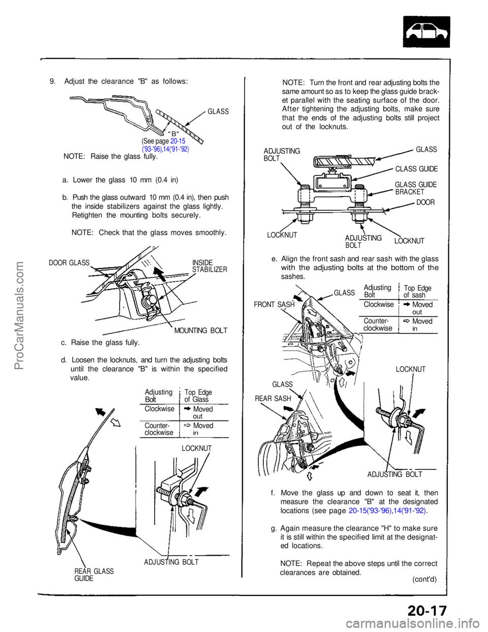
9. Adjust the clearance "B" as follows:
GLASS
a. Lower the glass 10 mm (0.4 in)
b. Push the glass outward 10 mm (0.4 in), then push the inside stabilizers against the glass lightly.Retighten the mounting bolts securely.
NOTE: Check that the glass moves smoothly.
DOOR GLASS
INSIDE
STABILIZER
MOUNTING BOLT
c. Raise the glass fully.
d. Loosen the locknuts, and turn the adjusting bolts until the clearance "B" is within the specified
value.
LOCKNUT
ADJUSTING BOLT
REAR GLASS
GUIDE
NOTE: Turn the front and rear adjusting bolts the
same amount so as to keep the glass guide brack-
et parallel with the seating surface of the door.
After tightening the adjusting bolts, make sure
that the ends of the adjusting bolts still project
out of the locknuts.
ADJUSTING
BOLT
GLASS
CLASS GUIDE
LOCKNUT
ADJUSTING
BOLT
GLASS GUIDE
BRACKET
DOOR
LOCKNUT
e. Align the front sash and rear sash with the glass
with the adjusting bolts at the bottom of the
sashes.
FRONT SASH
ADJUSTING BOLT
f. Move the glass up and down to seat it, then measure the clearance "B" at the designated
locations (see page 20-15('93-'96),14('91-'92).
g. Again measure the clearance "H" to make sure it is still within the specified limit at the designat-
ed locations.
NOTE: Repeat the above steps until the correct
clearances are obtained. (cont'd)
(See page 20-15
('93-'96),14('91-'92)
NOTE: Raise the glass fully.
Adjusting
Bolt
Top Edge
of Glass
Clockwise
Moved
out
Counter-
clockwise
Moved
in
LOCKNUT
GLASS
REAR SASH
GLASS
Adjusting
Bolt
Top Edge
of sash
Clockwise
Moved
out
Counter-
clockwise
Moved
in
"B"ProCarManuals.com
Page 577 of 1640
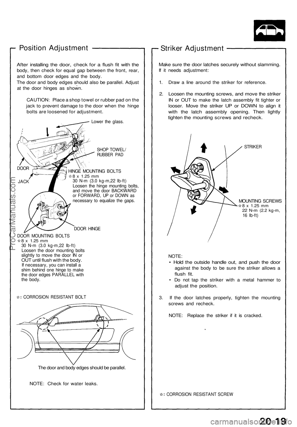
Position Adjustmen t
After installin g th e door , chec k fo r a flus h fi t wit h th e
body , the n chec k fo r equa l ga p betwee n th e front , rear ,
an d botto m doo r edge s an d th e body .
Th e doo r an d bod y edge s shoul d als o b e parallel . Adjus t
a t th e doo r hinge s a s shown .
CAUTION : Plac e a sho p towe l o r rubbe r pa d o n th e
jac k t o preven t damag e t o th e doo r whe n th e hing e
bolt s ar e loosene d fo r adjustment .
Lower th e glass .
SHOP TOWEL /RUBBER PA D
HING E MOUNTIN G BOLT S8 x 1.2 5 mm30 N- m (3. 0 kg-m,2 2 Ib-ft )Loose n th e hing e mountin g bolts ,and mov e th e doo r BACKWAR Dor FORWARD , U P o r DOW N a snecessar y t o equaliz e th e gaps .
DOOR HING E
DOOR MOUNTIN G BOLT S8 x 1.2 5 mm30 N- m (3. 0 kg-m,2 2 Ib-ft )Loose n th e doo r mountin g bolt sslightl y t o mov e th e doo r I N o rOU T unti l flus h wit h th e body .If necessary , yo u ca n instal l ashi m behin d on e hing e t o mak ethe doo r edge s PARALLE L wit hthe body .
CORROSIO N RESISTAN T BOL T
The doo r an d bod y edge s shoul d b e parallel .
NOTE : Chec k fo r wate r leaks .
Striker Adjustmen t
Make sur e th e doo r latche s securel y withou t slamming .
If i t need s adjustment :
1 . Dra w a lin e aroun d th e strike r fo r reference .
2. Loose n th e mountin g screws , an d mov e th e strike r
IN o r OU T t o mak e th e latc h assembl y fi t tighte r o r
looser . Mov e th e strike r U P o r DOW N to alig n i t
wit h th e latc h assembl y opening . The n lightl y
tighten th e mountin g screw s an d recheck .
STRIKER
MOUNTIN G SCREW S8 x 1.2 5 mm22 N- m (2. 2 kg-m ,16 Ib-ft )
NOTE :
• Hol d th e outsid e handl e out , an d pus h th e doo r
agains t th e bod y t o b e sur e th e strike r allow s a
flus h fit .
• D o no t ta p th e strike r wit h a meta l hamme r t o
adjus t th e position .
3. I f th e doo r latche s properly , tighte n th e mountin g
screw s an d recheck .
NOTE : Replac e th e strike r i f i t i s cracked .
CORROSIO N RESISTAN T SCRE W
DOOR
JACK
ProCarManuals.com
Page 583 of 1640
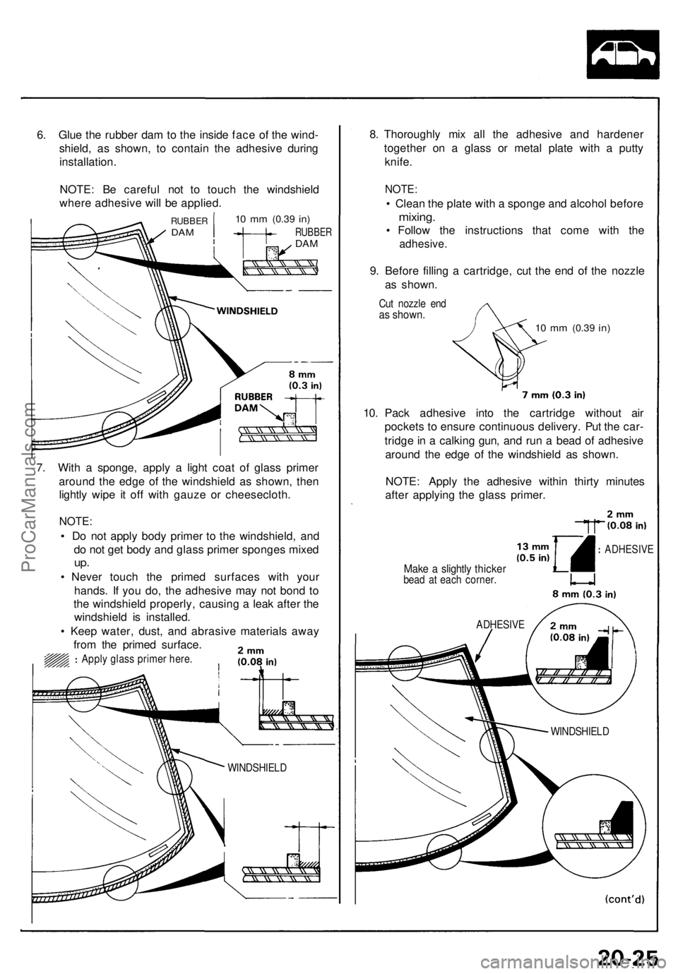
6. Glu e th e rubbe r da m to th e insid e fac e o f th e wind -
shield , a s shown , t o contai n th e adhesiv e durin g
installation .
NOTE : B e carefu l no t t o touc h th e windshiel d
wher e adhesiv e wil l b e applied .
10 m m (0.3 9 in)
RUBBE RDAM
RUBBE RDAM
7. Wit h a sponge , appl y a ligh t coa t o f glas s prime r
aroun d th e edg e o f th e windshiel d a s shown , the n
lightl y wip e i t of f wit h gauz e o r cheesecloth .
NOTE:
• D o no t appl y bod y primer to th e windshield , an d
d o no t ge t bod y an d glas s prime r sponge s mixe d
up.
• Neve r touc h th e prime d surface s wit h you r
hands . I f yo u do , th e adhesiv e ma y no t bon d t o
th e windshiel d properly , causin g a lea k afte r th e
windshiel d i s installed .
• Kee p water , dust , an d abrasiv e material s awa y
fro m th e prime d surface .
Apply glas s prime r here .
8. Thoroughl y mi x al l th e adhesiv e an d hardene r
togethe r o n a glas s o r meta l plat e wit h a putt y
knife .
NOTE :
• Clea n th e plat e wit h a spong e an d alcoho l befor e
mixing .
• Follo w th e instruction s tha t com e wit h th e
adhesive .
9. Befor e fillin g a cartridge , cu t th e en d of the nozzl e
a s shown .
Cut nozzl e en das shown .
10 m m (0. 39 in )
10. Pac k adhesiv e int o th e cartridg e withou t ai r
pocket s t o ensur e continuou s delivery . Pu t th e car -
tridg e in a calkin g gun , an d ru n a bea d of adhesiv e
aroun d th e edg e of the windshiel d a s shown .
NOTE : Appl y th e adhesiv e withi n thirt y minute s
afte r applyin g th e glas s primer .
Make a slightl y thicke rbead a t eac h corner .
ADHESIV E
WINDSHIEL D ADHESIV
E
WINDSHIEL D
ProCarManuals.com
Page 584 of 1640
Windshield
Installation
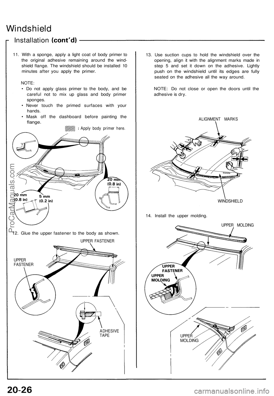
11. Wit h a sponge , appl y a ligh t coa t o f bod y prime r t o
th e origina l adhesiv e remainin g aroun d th e wind -
shiel d flange . Th e windshiel d shoul d b e installe d 1 0
minute s afte r yo u appl y th e primer .
NOTE:
• D o no t appl y glas s prime r t o th e body , an d b e
carefu l no t t o mi x u p glas s an d bod y prime r
sponges .
• Neve r touc h th e prime d surface s wit h you r
hands .
• Mas k of f th e dashboar d befor e paintin g th e
flange .
Apply bod y prime r here .
12. Glu e th e uppe r fastene r t o th e bod y a s shown .
UPPER FASTENE R
UPPE R
FASTENE R
13. Us e suctio n cup s t o hol d th e windshiel d ove r th e
opening , alig n i t wit h th e alignmen t mark s mad e i n
ste p 5 an d se t i t dow n o n th e adhesive . Lightl y
push o n th e windshiel d unti l it s edge s ar e full y
seate d o n th e adhesiv e al l th e wa y around .
NOTE : D o no t clos e o r ope n th e door s unti l th e
adhesiv e is dry .
ALIGNMEN T MARK S
14. Instal l th e uppe r molding .
WINDSHIEL D
UPPER MOLDIN G
ADHESIV E
TAP E
UPPE RMOLDIN G
ProCarManuals.com
Page 590 of 1640
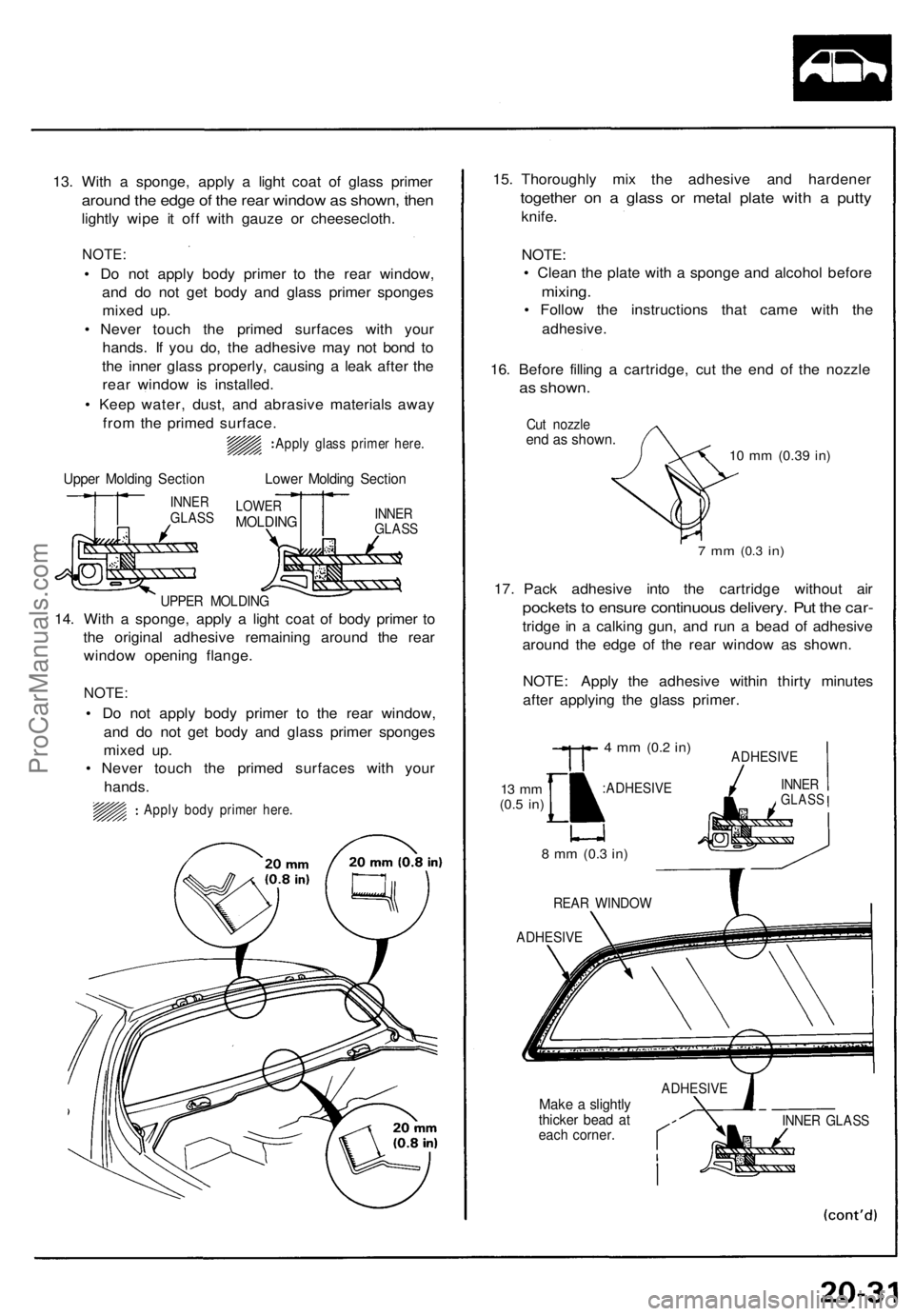
13. With a sponge, apply a light coat of glass primer
around the edge of the rear window as shown, then
lightly wipe it off with gauze or cheesecloth.
NOTE:
• Do not apply body primer to the rear window,
and do not get body and glass primer sponges
mixed up.
• Never touch the primed surfaces with your
hands. If you do, the adhesive may not bond to
the inner glass properly, causing a leak after the
rear window is installed.
• Keep water, dust, and abrasive materials away
from the primed surface.
Apply glass primer here.
Upper Molding Section
INNER
GLASS
Lower Molding Section
LOWER
MOLDING
INNER
GLASS
UPPER MOLDING
14. With a sponge, apply a light coat of body primer to
the original adhesive remaining around the rear
window opening flange.
NOTE:
• Do not apply body primer to the rear window,
and do not get body and glass primer sponges
mixed up.
• Never touch the primed surfaces with your
hands.
Apply body primer here.
15. Thoroughly mix the adhesive and hardener
together on a glass or metal plate with a putty
knife.
NOTE:
• Clean the plate with a sponge and alcohol before
mixing.
• Follow the instructions that came with the
adhesive.
16. Before filling a cartridge, cut the end of the nozzle
as shown.
Cut nozzle
end as shown.
10 mm
(0.39
in)
7 mm
(0.3
in)
17. Pack adhesive into the cartridge without air
pockets to ensure continuous delivery. Put the car-
tridge in a calking gun, and run a bead of adhesive
around the edge of the rear window as shown.
NOTE: Apply the adhesive within thirty minutes
after applying the glass primer.
13 mm
(0.5
in)
4 mm
(0.2
in)
:ADHESIVE
ADHESIVE
8 mm
(0.3
in)
REAR WINDOW
ADHESIVE
ADHESIVE
Make a slightly
thicker bead at
each corner.
INNER GLASS
INNER
GLASSProCarManuals.com
Page 591 of 1640
Rear Windo w
Installatio n
18. Us e suctio n cup s t o hol d th e rea r windo w ove r th e
opening , alig n i t wit h th e alignmen t mark s mad e in
ste p 1 1 an d se t i t dow n o n th e adhesive . Lightl y
push o n th e rea r windo w unti l it s edge s ar e full y
seate d o n th e adhesiv e al l th e wa y around .
NOTE : D o no t clos e o r ope n th e door s unti l th e
adhesiv e is dry .
REA R WINDO W
ALIGNMEN TMARKS
19. Afte r th e adhesiv e is dry , spra y wate r ove r th e rea r
windo w an d chec k fo r leaks . Mar k leakin g area s
an d le t th e rea r windo w dry , the n sea l with sealant .
NOTE: Le t th e ca r stan d fo r a t leas t fou r hour s
after rea r windo w installation . I f th e ca r ha s t o b e
use d withi n th e firs t fou r hours , i t mus t b e drive n
slowly .
20. Connec t th e rea r defogge r sub-harnes s an d groun d
cable/antenn a lead , the n instal l th e grommets .
21 . Reinstal l al l remainin g remove d parts .
ProCarManuals.com