1991 ACURA NSX alternator
[x] Cancel search: alternatorPage 76 of 1640
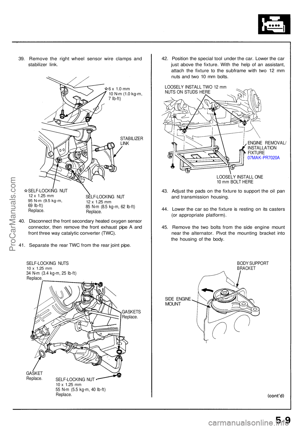
39. Remov e th e righ t whee l senso r wir e clamp s an d
stabilize r link .
6 x 1. 0 m m10 N- m (1. 0 kg-m ,7 Ib-ft )
STABILIZE RLINK
SELF-LOCKIN G NU T
12 x 1.2 5 mm95 N- m (9. 5 kg-m ,69 Ib-ft )Replace .
SELF-LOCKIN G NU T12 x 1.2 5 mm85 N- m (8. 5 kg-m , 6 2 Ib-ft )
Replace .
40. Disconnec t th e fron t secondar y heate d oxyge n senso r
connector , the n remov e th e fron t exhaus t pip e A an d
fron t thre e wa y catalyti c converte r (TWC) .
41 . Separat e th e rea r TW C fro m th e rea r join t pipe .
SELF-LOCKIN G NUT S10 x 1.2 5 mm34 N- m (3. 4 kg-m , 2 5 Ib-ft )Replace .
GASKET SReplace.
GASKETReplace .SELF-LOCKIN G NU T •10 x 1.2 5 mm55 N- m (5. 5 kg-m , 4 0 Ib-ft )Replace .
42. Positio n th e specia l too l unde r th e car . Lowe r th e ca r
jus t abov e th e fixture . Wit h th e hel p o f a n assistant ,
attac h th e fixtur e t o th e subfram e wit h tw o 1 2 m m
nut s an d tw o 1 0 m m bolts .
LOOSEL Y INSTAL L TW O 1 2 m m
NUT S O N STUD S HER E
ENGINE REMOVAL /
INSTALLATIO N
FIXTURE07MAK-PR7020 A
LOOSEL Y INSTAL L ON E
1 0 m m BOL T HER E
43. Adjus t th e pad s o n th e fixtur e t o suppor t th e oi l pa n
an d transmissio n housing .
44 . Lowe r th e ca r s o th e fixtur e i s restin g o n it s caster s
(o r appropriat e platform) .
45 . Remov e th e tw o bolt s fro m th e sid e engin e moun t
nea r th e alternator . Pivo t th e mountin g bracke t int o
th e housin g o f th e body .
BODY SUPPOR TBRACKET
SIDE ENGIN EMOUNT
ProCarManuals.com
Page 80 of 1640
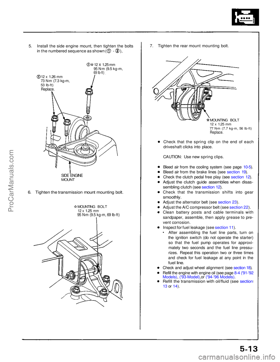
5. Install the side engine mount, then tighten the bolts
in the numbered sequence as shown ( - ),
12 x
1.26
mm
73 N·m
(7.3 kg-m,
53 Ib-ft)
Replace.
12 x
1.25
mm
95 N·m
(9.5 kg-m,
69 Ib-ft)
SIDE ENGINE
MOUNT
6. Tighten the transmission mount mounting bolt.
MOUNTING BOLT
12 x
1.25
mm
95 N·m (9.5 kg-m, 69 Ib-ft)
7. Tighten the rear mount mounting bolt.
MOUNTING BOLT
12 x
1.25
mm
77 N·m (7.7 kg-m, 56 Ib-ft)
Replace.
Check that the spring clip on the end of each
driveshaft clicks into place.
CAUTION: Use new spring clips.
Bleed air from the cooling system (see page 10-5).
Bleed air from the brake lines {see section 19).
Check the clutch pedal free play (see section 12).
Adjust the clutch guide assemblies when disas-
sembling clutch (see section 12).
Check that the transmission shifts into gear
smoothly.
Adjust the alternator belt (see section 23).
Adjust the A/C compressor belt (see section 22).
Clean battery posts and cable terminals with
sandpaper, assemble, then apply grease to pre-
vent corrosion.
Inspect for fuel leakage (see section 11). After assembling the fuel line parts, turn on
the ignition switch (do not operate the starter) so that the fuel pump operates for approxi-
mately two seconds and the fuel line pressu-
rizes. Repeat this operation two or three times
and check for fuel leakage at any point in the
fuel line.
Check and adjust wheel alignment (see section 18).
Refill the engine with engine oil (see page 8-4 ('91-'92
Models), ('93-Model),or ('94-'96 Models).
Refill the transmission with oil/fluid (see section
13 or
14).ProCarManuals.com
Page 91 of 1640
Timing Belt
Removal (cont'd)
7. Remove the breather hose and the air cleaner hous-
in
g
(see page 6-25 ('91-'93) or ('94-'96) )
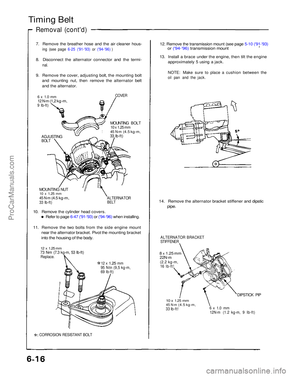
8. Disconnect the alternator connector and the termi-
nal.
9. Remove the cover, adjusting bolt, the mounting bolt and mounting nut, then remove the alternator belt
and the alternator.
COVER
6 x 1.0 mm
12 N·m
(1,2 kg-m,
9 Ib-ft)
MOUNTING BOLT
10 x 1.25 mm
45 N·m
(4.5 kg-m,
33 Ib-ft)
ADJUSTING
BOLT
MOUNTING NUT
10 x
1.25
mm
45 N·m
(4.5 kg-m,
33 Ib-ft)
ALTERNATOR
BELT
10. Remove the cylinder head covers.
Refer to page 6-47 ('91-'93) or ('94-'96) when installing.
11. Remove the two bolts from the side engine mount
near the alternator bracket. Pivot the mounting bracket
into the housing of the body.
12 x 1.25 mm
73 N·m (7.3 kg-m, 53 Ib-ft)
Replace.
12 x
1.25
mm
95 N·tn (9,5 kg-m,
69 Ib-ft)
CORROSION RESISTANT BOLT
12. Remove the transmission mount (see page 5-10 ('91-'93)
or ('94-'96) transmission mount
13. Install a brace under the engine, then tilt the engine
approximately 5 using a jack.
NOTE: Make sure to place a cushion between the
oil pan and the jack.
14. Remove the alternator bracket stiffener and dipstic
pipe.
ALTERNATOR BRACKET
STIFFENER
8 x
1.25
mm
22N·m
(2.2 kg-m,
16 lb-ft!
10 x
1.25
mm
45 N·m
(4.5 kg-m,
33 Ib-ft!
6 x 1.0 mm
12N·m (1.2 kg-m, 9 Ib-ft)
DIPSTICK PIPProCarManuals.com
Page 94 of 1640
6. Adjust the timing belt (see page 6-14 ('91-'93) or ('94-'96))
7. Install the lower cover and middle covers.
8. Install the crankshaft pulley, then tighten the pulley
bolt (see page 6-12 ('91-'93) or ('94-'96))
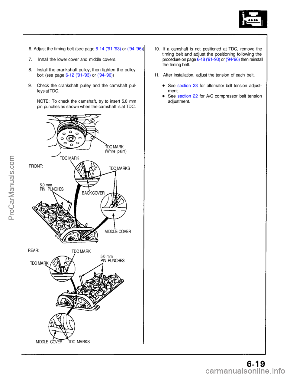
9. Check the crankshaft pulley and the camshaft pul- leys at TDC.
NOTE: To check the camshaft, try to insert 5.0 mm
pin punches as shown when the camshaft is at TDC.
TDC MARK
(White paint)
TDC MARK
FRONT:
TDC MARKS
5.0 mm
PIN PUNCHES BACK COVER
MIDDLE COVER
REAR: TDC MARK
5.0 mm
PIN PUNCHES
TDC MARK
MIDDLE COVER
TDC MARKS
10. If a camshaft is not positioned at TDC, remove the
timing belt and adjust the positioning following the
procedure on page 6-18 ('91-'93) or ('94-'96) then reinstall
the timing belt.
11. After installation, adjust the tension of each belt.
See section 23 for alternator belt tension adjust-
ment.
See section 22 for A/C compressor belt tension
adjustment.ProCarManuals.com
Page 102 of 1640

24. Remove the engine wire harness connectors and
wire harness clamps from the cylinder head and
intake manifold, Six injector connectors
Intake air temperature (IAT) sensor connector
CKP/CYP sensor connector
Heated oxygen sensor (HO2S) connectors
Ignition control module (ICM) connectors
Engine coolant temperature (ECT) sensor connec-
tor
ECT gauge sending unit connector
ECT switch connector
Exhaust gas recirculation (EGR) valve lift sensor
connector
Throttle position sensor connector Engine oil pressure gauge sending unit connector
Knock sensor connector
VTEC solenoid valve connectors
VTEC pressure switch connectors
Engine oil pressure switch connector
Alternator connector
Alternator terminal
Throttle body 6P connector
25. Remove the ignition coils and connector.
26. Remove the EGR pipe and intake manifold assem- bly.
8 x 1.25mm
22 N·m (2.2 kg-m, 16 Ib-ft)
6 x 1.0 mm
12 N·m
(1.2 kg-m,
9 lb-ft)
GASKETS
Replace. INTAKE
MANIFOLD
ASSEMBLY
GASKET
Replace.
27. Loosen the adjusting nut and idler pulley center nut,
then remove the air conditioning compressor belt
(see page 6-17('91-'93) or ('94-'96)).
28. Remove the cover, adjusting bolt, mounting bolt and mounting nut, then remove the alternator belt
and alternator.
COVER
MOUNTING BOLT
10 x
1.25
mm
45 N·m (4.5 kg·m,
33 Ib-ft)
MOUNTING NUT
10 x
1.25
mm
45 N·m (4.5 kg·m.
33 Ib·ft)
ALTERNATOR
BELT
29. Disconnect the knock sensor connector, then remove
the wire holder.
6 x 1.0 mm
12N·m (1.2 kg-m, 9 Ib-ft)
KNOCK SENSOR
WIRE HOLDER
(cont'd)
6 x 1.0 mm
12 N·m (1.2 kg-m, 9 Ib-ft)
ADJUSTING
BOLTProCarManuals.com
Page 103 of 1640

30. Remove the water passage. \")
Cylinder Heads
Removal (cont'd)
30. Remove the water passage. \
\
32. Remove the alternator bracket stiffener (see page 6-16
('91-'93) or ('94-'96).
33. Remove the alternator bracket.
8 x
1.25
mm
22 N·m (2.2 kg-m, 16 Ib-ft)
ALTERNATOR
BRACKET
10 x
1,25
mm
45N·m (4.5 kg-m,
33 Ib-ft)
34. Remove the timing belt (see page 6-15 ('91-'93) or ('94-'96)).
the timing belt
35. Remove the camshaft pulleys.
RETAINING
BOLTS
CAMSHAFT PULLEYS
GROUND
CABLE
WASHER
CYLINDER HEAD
COVER
31. Remove the cylinder head covers.
0-RINGS
Replace.
CONNECTING PIPE
WATER PASSAGE
8 x 1.25 mm
22 N·m (2.2 kg-m, 16 Ib-ft)ProCarManuals.com
Page 230 of 1640
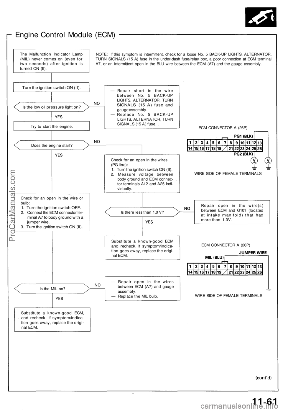
Engine Control Module (ECM)
NOTE: If this symptom is intermittent, check for a loose No. 5 BACK-UP LIGHTS, ALTERNATOR,
TURN SIGNALS (15 A) fuse in the under-dash fuse/relay box, a poor connection at ECM terminal
A7, or an intermittent open in the BLU wire between the ECM (A7) and the gauge assembly.
Is the low oil pressure light on?
Try to start the engine.
Does the engine start?
Check for an open in the wire or
bulb:
1. Turn the ignition switch OFF.
2. Connect the ECM connector ter-
minal A7 to body ground with a
jumper wire.
3. Turn the ignition switch ON (II).
Is the MIL on?
Substitute a known-good ECM,
and recheck. If symptom/indica-
tion goes away, replace the origi-
nal
ECM.
— Repair short in the wire
between No. 5 BACK-UP
LIGHTS, ALTERNATOR, TURN
SIGNALS (15 A) fuse and
gauge assembly.
— Replace No. 5 BACK-UP
LIGHTS, ALTERNATOR, TURN
SIGNALS (15 A) fuse.
ECM CONNECTOR A (26P)
Check for an open in the wires
(PG line):
1. Turn the ignition switch ON (II).
2. Measure voltage between
body ground and ECM connec-
tor terminals A12 and A25 indi-
vidually.
WIRE SIDE OF FEMALE TERMINALS
Is there less than 1.0 V?
Repair open in the wire(s)
between ECM and G101 (located
at intake manifold) that had
more than 1.0V.
— Repair open in the wires
between ECM (A7) and gauge
assembly.
— Replace the MIL bulb.
WIRE SIDE OF FEMALE TERMINALS
ECM CONNECTOR A (26P)
Substitute a known-good ECM
and recheck. If symptom/indica-
tion goes away, replace the origi-
nal
ECM.
Turn the ignition switch ON (II).
The Malfunction Indicator Lamp
(MIL) never comes on (even for
two seconds) after ignition is
turned ON (II).ProCarManuals.com
Page 238 of 1640
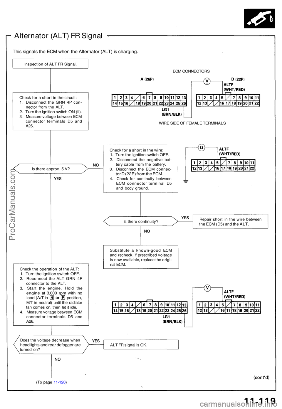
Alternator (ALT ) F R Signa l
This signal s th e EC M whe n th e Alternato r (ALT ) i s charging .
Inspection o f AL T F R Signal .
ECM CONNECTOR S
WIR E SID E O F FEMAL E TERMINAL S
Chec k fo r a shor t i n th e wire :
1. Tur n th e ignitio n switc h OFF .2. Disconnec t th e negativ e bat -
ter y cabl e fro m th e battery .
3 . Disconnec t th e EC M connec -
tor D (22P ) fro m th e ECM .4. Chec k fo r continuit y betwee n
EC M connecto r termina l D 5
an d bod y ground .
I
s ther e approx . 5 V ?
Chec
k fo r a shor t i n th e circuit :
1 . Disconnec t th e GR N 4 P con -
necto r fro m th e ALT .
2. Tur n th e ignitio n switc h O N (II) .3. Measur e voltag e betwee n EC M
connecto r terminal s D 5 an d
A26 .
Is ther e continuity ? Repai
r shor t i n th e wir e betwee nthe EC M (D5 ) and th e ALT .
Substitut e a known-goo d EC M
an d recheck . I f prescribe d voltag e
i s no w available , replac e th e origi -
nal ECM .Chec k th e operatio n o f th e ALT :1. Tur n th e ignitio n switc h OFF .2. Reconnec t th e AL T GR N 4 P
connecto r t o th e ALT .
3 . Star t th e engine . Hol d th e
engin e a t 3,00 0 rp m wit h n oloa d (A/ T in position ,M/T in neutral ) unti l th e radiato r
fa n come s on , the n le t i t idle .
4 . Measur e voltag e betwee n EC M
connecto r terminal s D 5 an d
A26.
Doe s th e voltag e decreas e whe nhead light s an d rea r defogge r ar eturne d on ? AL
T F R signa l i s OK .
(T o pag e 11-120 )
ProCarManuals.com