1991 ACURA NSX jump start terminals
[x] Cancel search: jump start terminalsPage 230 of 1640
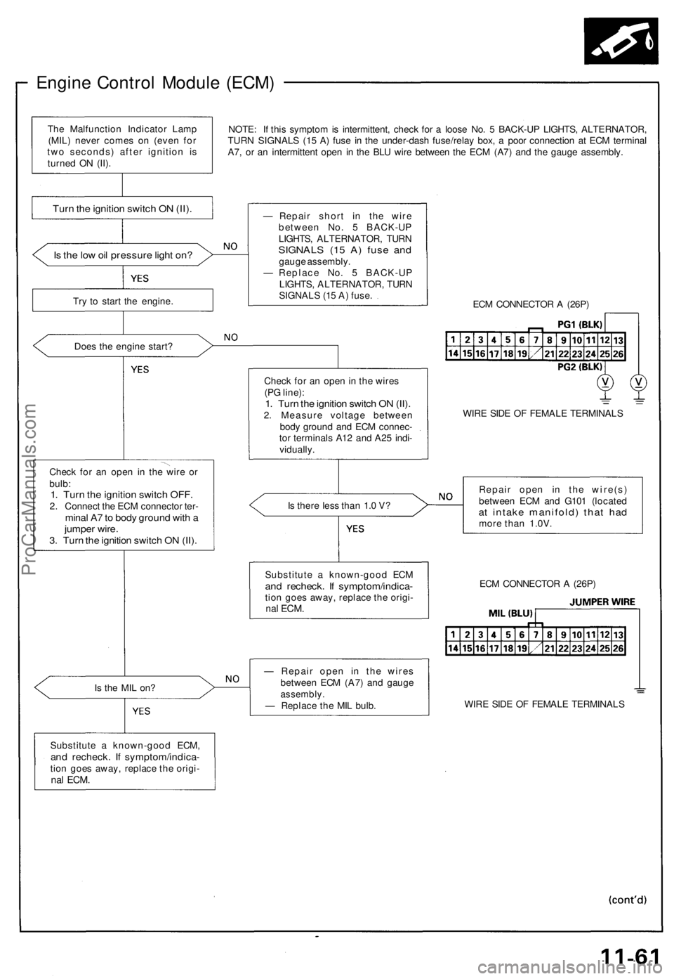
Engine Control Module (ECM)
NOTE: If this symptom is intermittent, check for a loose No. 5 BACK-UP LIGHTS, ALTERNATOR,
TURN SIGNALS (15 A) fuse in the under-dash fuse/relay box, a poor connection at ECM terminal
A7, or an intermittent open in the BLU wire between the ECM (A7) and the gauge assembly.
Is the low oil pressure light on?
Try to start the engine.
Does the engine start?
Check for an open in the wire or
bulb:
1. Turn the ignition switch OFF.
2. Connect the ECM connector ter-
minal A7 to body ground with a
jumper wire.
3. Turn the ignition switch ON (II).
Is the MIL on?
Substitute a known-good ECM,
and recheck. If symptom/indica-
tion goes away, replace the origi-
nal
ECM.
— Repair short in the wire
between No. 5 BACK-UP
LIGHTS, ALTERNATOR, TURN
SIGNALS (15 A) fuse and
gauge assembly.
— Replace No. 5 BACK-UP
LIGHTS, ALTERNATOR, TURN
SIGNALS (15 A) fuse.
ECM CONNECTOR A (26P)
Check for an open in the wires
(PG line):
1. Turn the ignition switch ON (II).
2. Measure voltage between
body ground and ECM connec-
tor terminals A12 and A25 indi-
vidually.
WIRE SIDE OF FEMALE TERMINALS
Is there less than 1.0 V?
Repair open in the wire(s)
between ECM and G101 (located
at intake manifold) that had
more than 1.0V.
— Repair open in the wires
between ECM (A7) and gauge
assembly.
— Replace the MIL bulb.
WIRE SIDE OF FEMALE TERMINALS
ECM CONNECTOR A (26P)
Substitute a known-good ECM
and recheck. If symptom/indica-
tion goes away, replace the origi-
nal
ECM.
Turn the ignition switch ON (II).
The Malfunction Indicator Lamp
(MIL) never comes on (even for
two seconds) after ignition is
turned ON (II).ProCarManuals.com
Page 531 of 1640
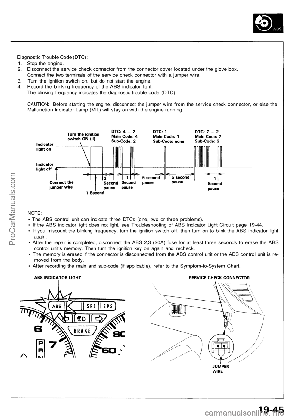
Diagnostic Trouble Code (DTC):
1. Stop the engine.
2. Disconnect the service check connector from the connector cover located under the glove box.
Connect the two terminals of the service check connector with a jumper wire.
3. Turn the ignition switch on, but do not start the engine.
4. Record the blinking frequency of the ABS indicator light.
The blinking frequency indicates the diagnostic trouble code (DTC).
CAUTION: Before starting the engine, disconnect the jumper wire from the service check connector, or else the
Malfunction Indicator Lamp (MIL) will stay on with the engine running.
NOTE:
• The ABS control unit can indicate three DTCs (one, two or three problems).
• If the ABS indicator light does not light, see Troubleshooting of ABS Indicator Light Circuit page 19-44.
• If you miscount the blinking frequency, turn the ignition switch off, then turn on to blink the ABS indicator light
again.
• After the repair is completed, disconnect the ABS 2,3 (20A) fuse for at least three seconds to erase the ABS
control unit's memory. Then turn the ignition key on again and recheck.
• The memory is erased if the connector is disconnected from the ABS control unit or the ABS control unit is re-
moved from the body.
• After recording the main and sub-code (if applicable), refer to the Symptom-to-System Chart.ProCarManuals.com
Page 795 of 1640
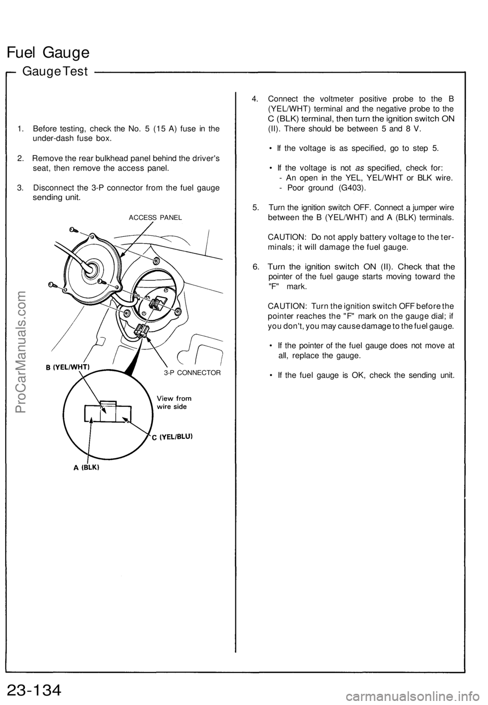
Fuel Gaug e
Gauge Tes t
1. Befor e testing , chec k th e No . 5 (1 5 A ) fus e i n th e
under-das h fus e box .
2 . Remov e th e rea r bulkhea d pane l behin d th e driver' s
seat , the n remov e th e acces s panel .
3 . Disconnec t th e 3- P connecto r fro m th e fue l gaug e
sendin g unit .
ACCES S PANE L
4. Connec t th e voltmete r positiv e prob e t o th e B
(YEL/WHT ) termina l an d th e negativ e prob e t o th e
C (BLK ) terminal , the n tur n th e ignitio n switc h O N
(II) . Ther e shoul d b e betwee n 5 an d 8 V .
• I f th e voltag e i s a s specified , g o t o ste p 5 .
• I f th e voltag e i s no t as specified , chec k for :
- A n ope n i n th e YEL , YEL/WH T o r BL K wire .
- Poo r groun d (G403) .
5 . Tur n th e ignitio n switc h OFF . Connec t a jumpe r wir e
betwee n th e B (YEL/WHT ) an d A (BLK ) terminals .
CAUTION : D o no t appl y batter y voltag e to th e ter -
minals ; i t wil l damag e th e fue l gauge .
6. Tur n th e ignitio n switc h O N (II) . Chec k tha t th e
pointe r o f th e fue l gaug e start s movin g towar d th e
"F " mark .
CAUTION : Tur n th e ignitio n switc h OF F befor e th e
pointe r reache s th e "F " mar k o n th e gaug e dial ; i f
yo u don't , yo u ma y caus e damag e to th e fue l gauge .
• I f th e pointe r o f th e fue l gaug e doe s no t mov e a t
all , replac e th e gauge .
• I f th e fue l gaug e i s OK , chec k th e sendin g unit .
23-13 4
3-P CONNECTO R
ProCarManuals.com
Page 1088 of 1640
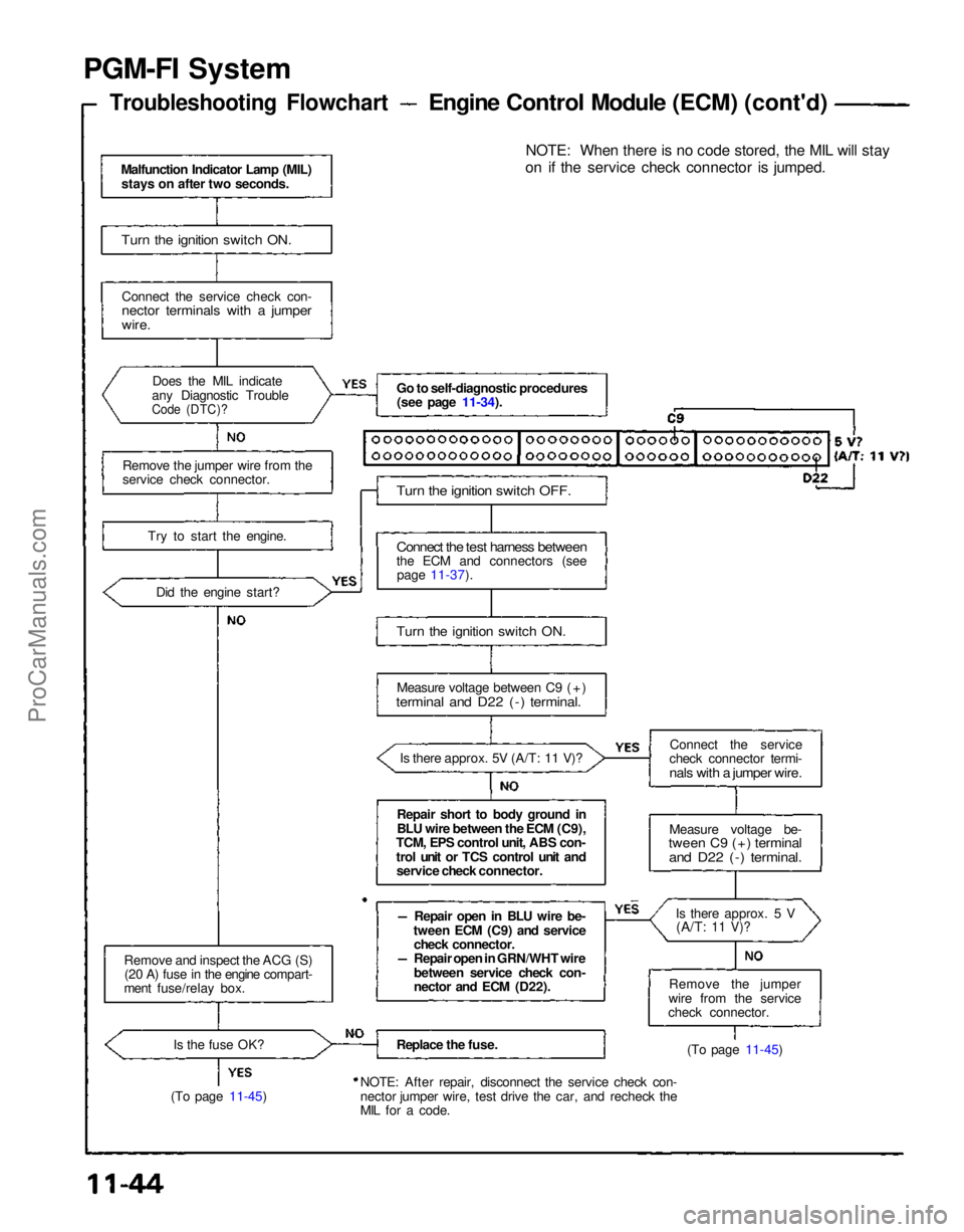
PGM-FI System
Troubleshooting Flowchart
Engine Control Module (ECM) (cont'd)
Malfunction Indicator Lamp (MIL) stays on after two seconds.
Turn the ignition switch ON.
Connect the service check con-
nector terminals with a jumper
wire.
Does the MIL indicate
any Diagnostic Trouble
Code (DTC)?
Remove the jumper wire from the
service check connector.
Try to start the engine.Did the engine start?
Remove and inspect the ACG (S) (20 A) fuse in the engine compart-
ment fuse/relay box.
Is the fuse OK?
(To page 11-45) Go to self-diagnostic procedures
(see page 11-34).
Turn the ignition switch OFF.
Connect the test harness between
the ECM and connectors (see page 11-37).
Turn the ignition switch ON.
Measure voltage between C9 (+)
terminal and D22 (-) terminal.
Is there approx. 5V (A/T: 11 V)?
Repair short to body ground in
BLU wire between the ECM (C9),
TCM, EPS control unit, ABS con-
trol unit or TCS control unit and service check connector.
Repair open in BLU wire be-
tween ECM (C9) and service check connector.
Repair open in GRN/WHT wire
between service check con-
nector and ECM (D22).
Replace the fuse.
NOTE: After repair, disconnect the service check con-
nector jumper wire, test drive the car, and recheck the
MIL for a code. NOTE: When there is no code stored, the MIL will stay
on if the service check connector is jumped.
Connect the service
check connector termi-
nals with a jumper wire.
Measure voltage be-
tween C9 (+) terminal
and D22 (-) terminal.
Is there approx. 5 V(A/T:
11 V)?
Remove the jumper
wire from the service
check connector.
(To page 11-45)ProCarManuals.com
Page 1122 of 1640
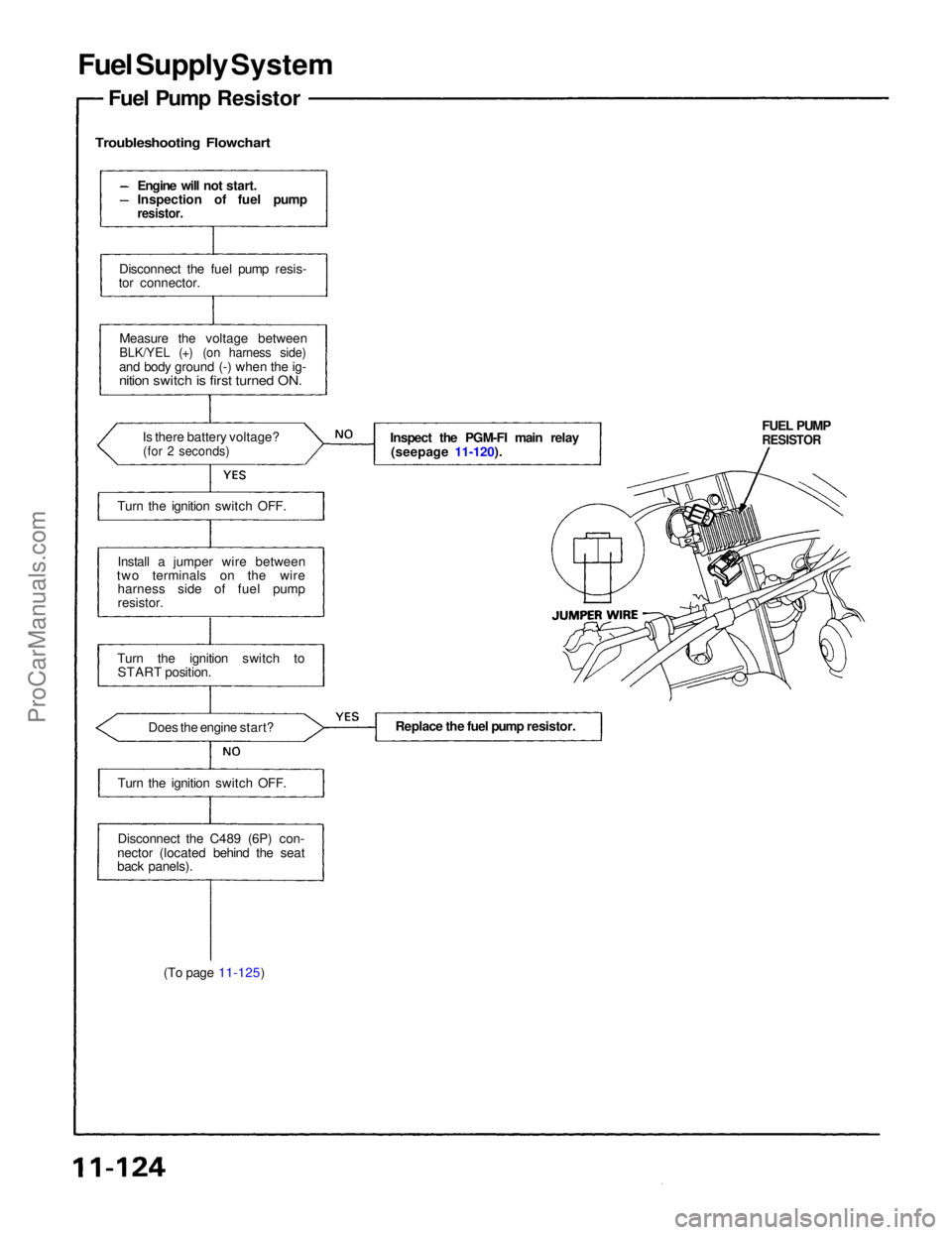
Fuel Supply System
Fuel Pump Resistor
Troubleshooting Flowchart
(To page 11-125) FUEL PUMP
RESISTOR
Inspect the PGM-FI main relay
(seepage 11-120).
Engine will not start.
Inspection of fuel pump
resistor.
Disconnect the fuel pump resis-
tor connector.
Measure the voltage between
BLK/YEL (+) (on harness side)
and body ground (-) when the ig-
nition switch is first turned ON.
Is there battery voltage?
(for 2 seconds)
Turn the ignition switch OFF.
Install a jumper wire between
two terminals on the wire harness side of fuel pump
resistor.
Turn the ignition switch to START position.
Does the engine start?
Turn the ignition switch OFF.
Disconnect the C489 (6P) con-
nector (located behind the seat
back panels). Replace the fuel pump resistor.ProCarManuals.com
Page 1335 of 1640
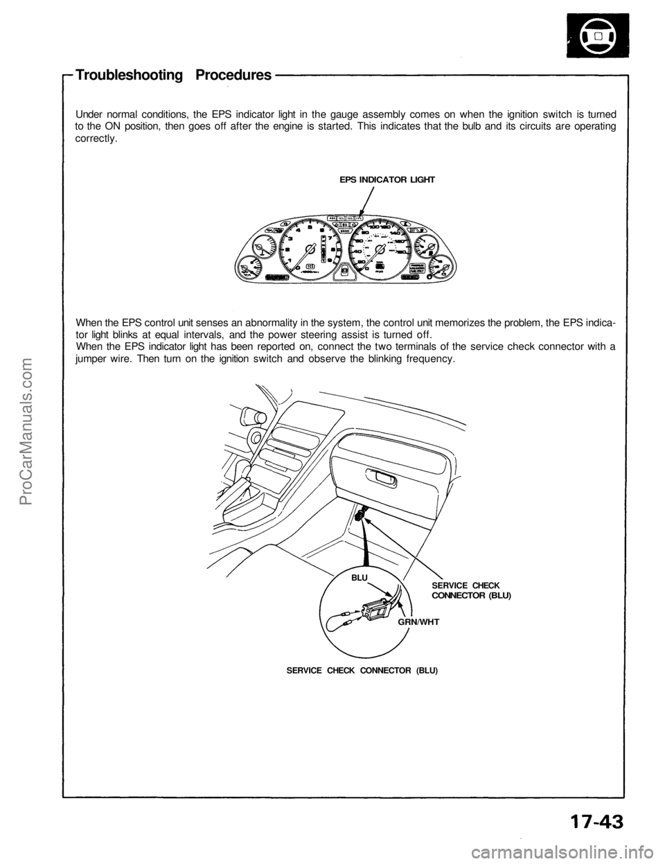
Troubleshooting Procedures
Under normal conditions, the EPS indicator light in the gauge assembly comes on when the ignition switch is turned
to the ON position, then goes off after the engine is started. This indicates that the bulb and its circuits are operating
correctly.
EPS INDICATOR LIGHT
When the EPS control unit senses an abnormality in the system, the control unit memorizes the problem, the EPS indica-
tor light blinks at equal intervals, and the power steering assist is turned off.
When the EPS indicator light has been reported on, connect the two terminals of the service check connector with a
jumper wire. Then turn on the ignition switch and observe the blinking frequency.
SERVICE CHECK
CONNECTOR (BLU)
GRN/WHT
SERVICE CHECK CONNECTOR (BLU)
BLUProCarManuals.com
Page 1365 of 1640
Troubleshooting
TCS Indicator Light
Temporary Driving Conditions:
1. The TCS indicator light will come on and the control unit memorizes the Diagnostic Trouble Code (DTC) under cer-
tain temporary conditions:
2. If the TCS indicator light does not come back on after correcting the tire or tire pressure problem, the TCS system is
OK.
NOTE: Remove the ABS 2.3 (20 A) fuse for at least 3 seconds to clear the DTC from the TCS control unit memory.
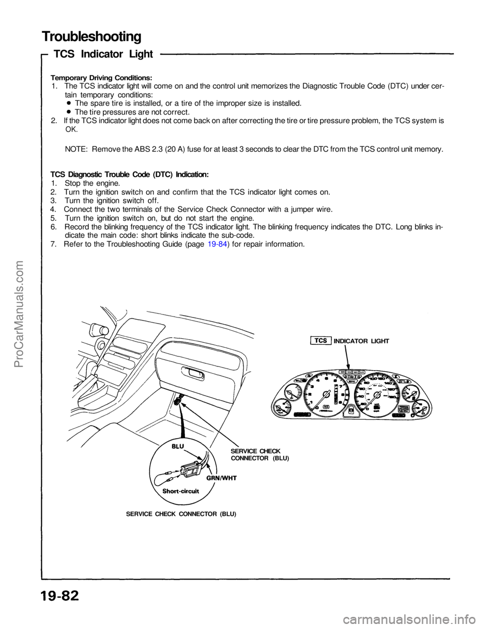
TCS Diagnostic Trouble Code (DTC) Indication: 1. Stop the engine.
2. Turn the ignition switch on and confirm that the TCS indicator light comes on.
3. Turn the ignition switch off.
4. Connect the two terminals of the Service Check Connector with a jumper wire.
5. Turn the ignition switch on, but do not start the engine.6. Record the blinking frequency of the TCS indicator light. The blinking frequency indicates the DTC. Long blinks in- dicate the main code: short blinks indicate the sub-code.
7. Refer to the Troubleshooting Guide (page 19-84) for repair information. The spare tire is installed, or a tire of the improper size is installed.
The tire pressures are not correct.
SERVICE CHECK CONNECTOR (BLU)
SERVICE CHECK
CONNECTOR (BLU)
INDICATOR LIGHTProCarManuals.com
Page 1393 of 1640
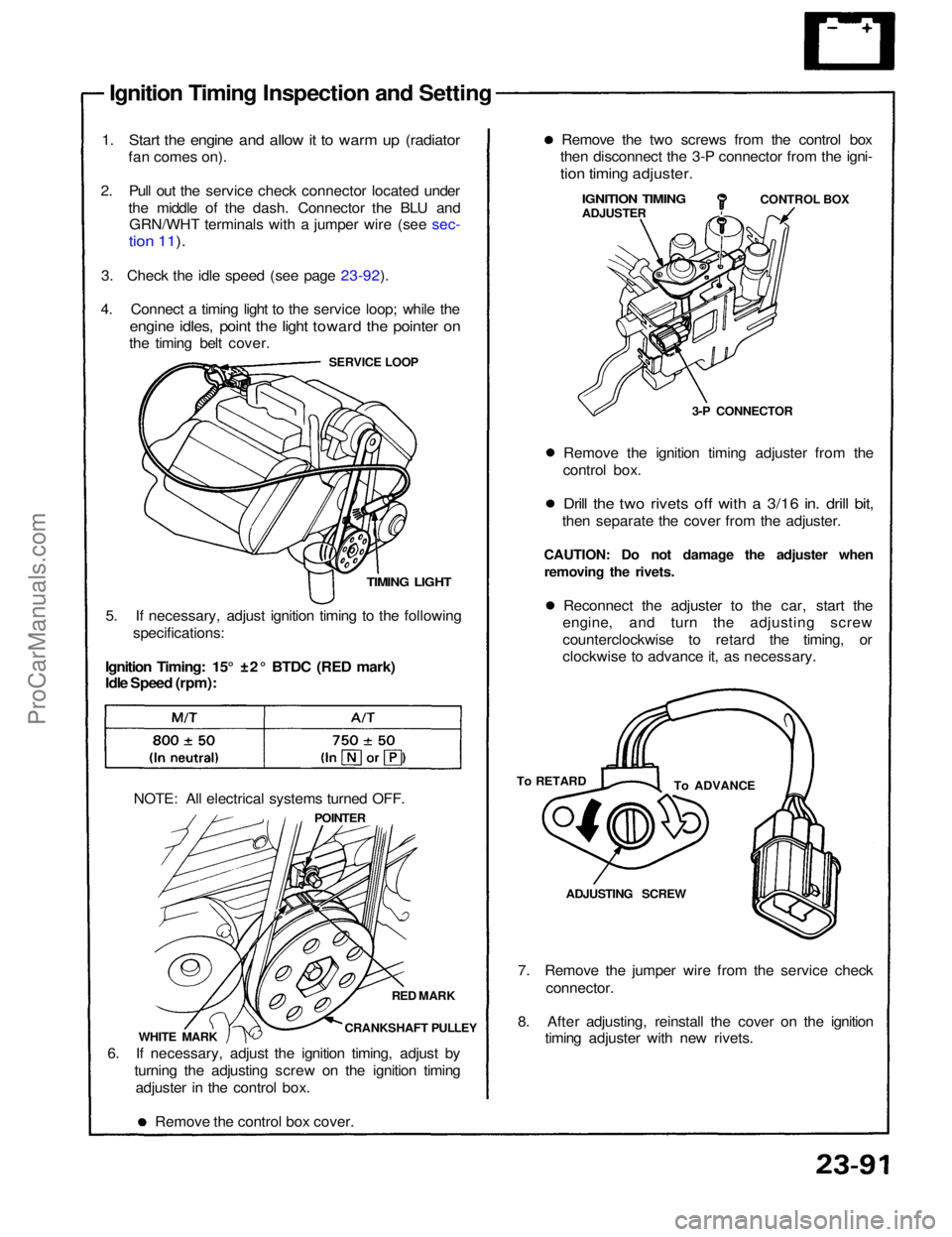
Ignition Timing Inspection and Setting
1. Start the engine and allow it to warm up (radiator
fan comes on).
2. Pull out the service check connector located under the middle of the dash. Connector the BLU andGRN/WHT terminals with a jumper wire (see sec-
tion 11).
3. Check the idle speed (see page 23-92).
4. Connect a timing light to the service loop; while the
engine idles, point the light toward the pointer on
the timing belt cover.
SERVICE LOOP
TIMING LIGHT
5. If necessary, adjust ignition timing to the following specifications:
Ignition Timing: 15° ±2° BTDC (RED mark)
Idle Speed (rpm):
NOTE: All electrical systems turned OFF. POINTER
RED MARK
CRANKSHAFT PULLEY
WHITE MARK
6. If necessary, adjust the ignition timing, adjust by turning the adjusting screw on the ignition timingadjuster in the control box.
Remove the control box cover. 7. Remove the jumper wire from the service check
connector.
8. After adjusting, reinstall the cover on the ignition timing adjuster with new rivets.ADJUSTING SCREW
To ADVANCE
To RETARD Reconnect the adjuster to the car, start the
engine, and turn the adjusting screw
counterclockwise to retard the timing, or
clockwise to advance it, as necessary.
CAUTION: Do not damage the adjuster when
removing the rivets. Remove the ignition timing adjuster from the
control box.
Drill the two rivets off with a 3/16 in. drill bit,
then separate the cover from the adjuster. 3-P CONNECTORCONTROL BOX
IGNITION TIMING
ADJUSTER
Remove the two screws from the control box
then disconnect the 3-P connector from the igni-
tion timing adjuster.ProCarManuals.com