1991 ACURA NSX change wheel
[x] Cancel search: change wheelPage 130 of 1640
Flywheel an d Driv e Plat e
Replacemen t
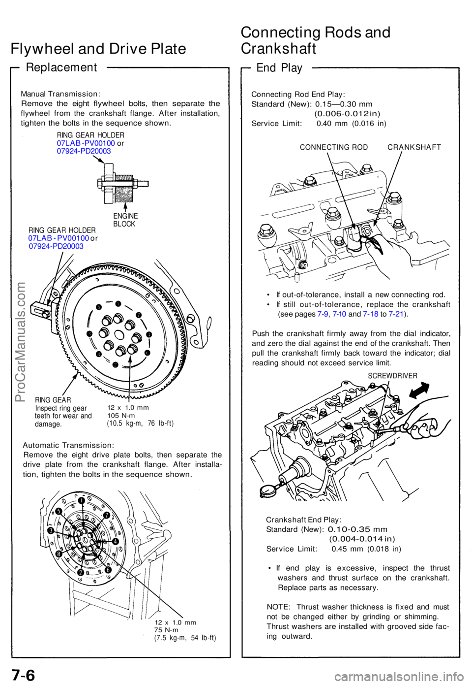
Manual Transmission :
Remove th e eigh t flywhee l bolts , the n separat e th e
flywhee l fro m th e crankshaf t flange . Afte r installation ,
tighten th e bolt s i n th e sequenc e shown .
RING GEA R HOLDE R07LAB -PV0010 0 o r
0792 4-PD2000 3
RING GEA R HOLDE R07LAB - PV00100 or
0792 4-PD2000 3
ENGINEBLOCK
RING GEA RInspec t rin g gea rteeth fo r wea r an ddamage .
12 x 1. 0 m m105 N- m(10. 5 kg-m , 7 6 Ib-ft )
Automati c Transmission :
Remov e th e eigh t driv e plat e bolts , the n separat e th e
driv e plat e fro m th e crankshaf t flange . Afte r installa -
tion, tighte n th e bolt s i n th e sequenc e shown .
12 x 1. 0 m m75 N- m(7.5 kg-m , 5 4 Ib-ft )
Connectin g Rod s an d
Crankshaf t
End Pla y
Connectin g Ro d En d Play :
Standar d (New) : 0.15—0.3 0 m m
(0.006-0.01 2 in )
Servic e Limit : 0.4 0 m m (0.01 6 in )
CONNECTIN G RO D CRANKSHAF T
• I f out-of-tolerance , instal l a ne w connectin g rod .
• I f stil l out-of-tolerance , replac e th e crankshaf t
(se e page s 7-9 , 7-1 0 an d 7-1 8 to 7-21 ).
Pus h th e crankshaf t firml y awa y fro m th e dia l indicator ,
an d zer o th e dia l agains t th e en d o f th e crankshaft . The n
pul l th e crankshaf t firml y bac k towar d th e indicator ; dia l
readin g shoul d no t excee d servic e limit .
SCREWDRIVE R
Crankshaft En d Play :
Standar d (New) :
0.10-0.3 5 mm
(0.004-0.01 4 in )
Servic e Limit : 0.4 5 m m (0.01 8 in )
• I f en d pla y i s excessive , inspec t th e thrus t
washer s an d thrus t surfac e o n th e crankshaft .
Replac e part s a s necessary .
NOTE : Thrus t washe r thicknes s i s fixe d an d mus t
no t b e change d eithe r b y grindin g o r shimming .
Thrus t washer s ar e installe d wit h groove d sid e fac -
in g outward .
ProCarManuals.com
Page 410 of 1640
System Description
Function and Operation
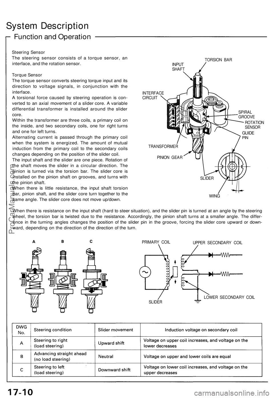
Steering Sensor
The steering sensor consists of a torque sensor, an
interface, and the rotation sensor.
Torque Sensor
The torque sensor converts steering torque input and its
direction to voltage signals, in conjunction with the
interface.
A torsional force caused by steering operation is con-
verted to an axial movement of a slider core. A variable
differential transformer is installed around the slider
core.
Within the transformer are three coils, a primary coil on
the inside, and two secondary coils, one for right turns
and one for left turns.
Alternating current is passed through the primary coil
when the system is energized. The amount of mutual
induction from the primary coil to the secondary coils
changes depending on the position of the slider coil.
The input shaft and the slider are one piece. Rotation of
the shaft moves the slider in a circular direction. The
pinion is turned via the torsion bar. The slider core is
installed on the pinion shaft on grooves, and turns with
the pinion shaft.
When there is little resistance, the input shaft torsion
bar, pinion shaft, and the slider core turn together to the
same angle. The slider core does not move up/down.
TORSION BAR
INPUT
SHAFT
INTERFACE
CIRCUIT
SPIRAL
GROOVE
ROTATION
SENSOR
GUIDE
PIN
TRANSFORMER
PINION GEAR
WING
When there is resistance on the input shaft (hard to steer situation), and the slider pin is turned at an angle by the steering
wheel, the torsion bar is twisted due to the resistance. Accordingly, the pinion shaft turns at a smaller angle. The differ-
ence in the turning angles changes the position of the slider pin in the groove, forcing the slider core upward or down-
ward, depending on the direction of the direction of the turn.
PRIMARY COIL
UPPER SECONDARY COIL
LOWER SECONDARY COIL
SLIDER
SLIDERProCarManuals.com
Page 411 of 1640
Rotation Sensor
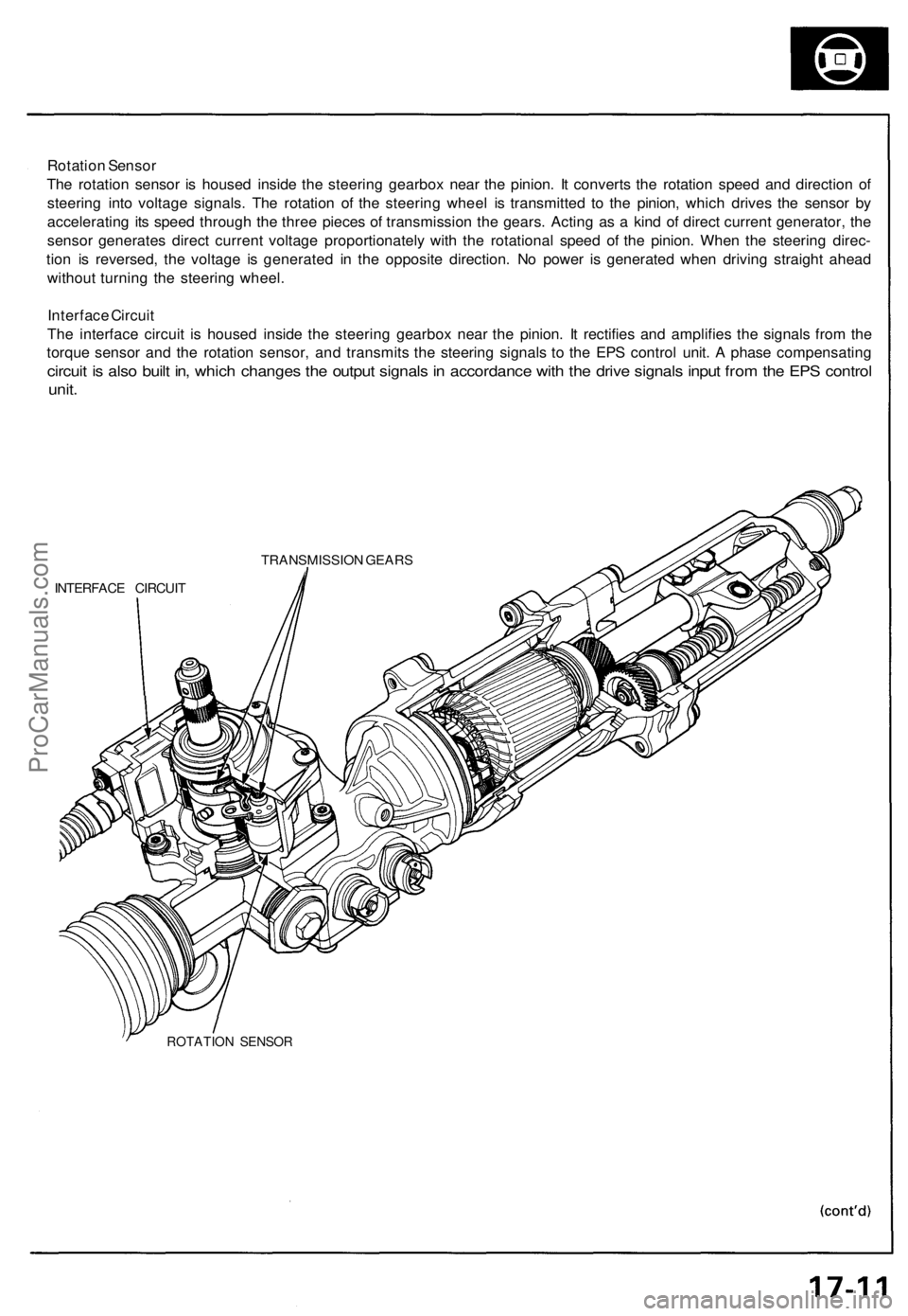
The rotation sensor is housed inside the steering gearbox near the pinion. It converts the rotation speed and direction of
steering into voltage signals. The rotation of the steering wheel is transmitted to the pinion, which drives the sensor by
accelerating its speed through the three pieces of transmission the gears. Acting as a kind of direct current generator, the
sensor generates direct current voltage proportionately with the rotational speed of the pinion. When the steering direc-
tion is reversed, the voltage is generated in the opposite direction. No power is generated when driving straight ahead
without turning the steering wheel.
Interface Circuit
The interface circuit is housed inside the steering gearbox near the pinion. It rectifies and amplifies the signals from the
torque sensor and the rotation sensor, and transmits the steering signals to the EPS control unit. A phase compensating
circuit is also built in, which changes the output signals in accordance with the drive signals input from the EPS control
unit.
TRANSMISSION GEARS
INTERFACE CIRCUIT
ROTATION SENSORProCarManuals.com
Page 450 of 1640
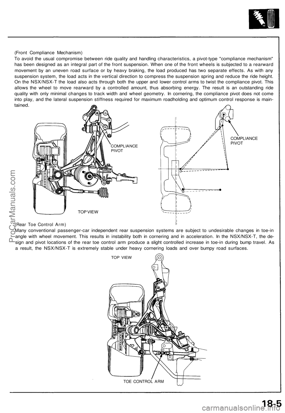
(Front Compliance Mechanism)
To avoid the usual compromise between ride quality and handling characteristics, a pivot-type "compliance mechanism"
has been designed as an integral part of the front suspension. When one of the front wheels is subjected to a rearward
movement by an uneven road surface or by heavy braking, the load produced has two separate effects. As with any
suspension system, the load acts in the vertical direction to compress the suspension spring and reduce the ride height.
On the NSX/NSX-T the load also acts through both the upper and lower control arms to twist the compliance pivot. This
allows the wheel to move rearward by a controlled amount, thus absorbing energy. The result is an outstanding ride
quality with only minimal changes to track width and wheel geometry. In cornering, the compliance pivot does not come
into play, and the lateral suspension stiffness required for maximum roadholding and optimum control response is main-
tained.
COMPLIANCE
PIVOT
TOP VIEW
(Rear Toe Control Arm)
Many conventional passenger-car independent rear suspension systems are subject to undesirable changes in toe-in
angle with wheel movement. This results in instability both in cornering and in acceleration. In the NSX/NSX-T, the de-
sign and pivot locations of the rear toe control arm produce a slight controlled increase in toe-in during bump travel. As
a result, the NSX/NSX-T is extremely stable under heavy cornering loads and over bumpy road surfaces.
TOP VIEW
TOE CONTROL ARM
COMPLIANCE
PIVOTProCarManuals.com
Page 452 of 1640
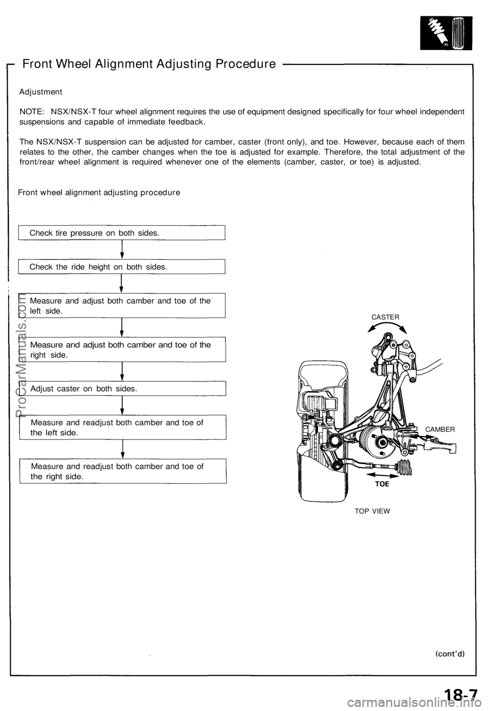
Front Wheel Alignment Adjusting Procedure
Adjustment
NOTE: NSX/NSX-T four wheel alignment requires the use of equipment designed specifically for four wheel independent
suspensions and capable of immediate feedback.
The NSX/NSX-T suspension can be adjusted for camber, caster (front only), and toe. However, because each of them
relates to the other, the camber changes when the toe is adjusted for example. Therefore, the total adjustment of the
front/rear wheel alignment is required whenever one of the elements (camber, caster, or toe) is adjusted.
Front wheel alignment adjusting procedure
Check tire pressure on both sides.
Check the ride height on both sides.
Measure and adjust both camber and toe of the
left side.
Measure and adjust both camber and toe of the
right side.
Adjust caster on both sides.
Measure and readjust both camber and toe of
the left side.
Measure and readjust both camber and toe of
the right side.
CASTER
TOP VIEW
CAMBERProCarManuals.com
Page 1165 of 1640
Description
The automatic transmission is a combination of a 3-element torque converter and a triple-shaft electronically controlled
automatic transmission which provides 4 speeds forward and 1 in reverse. The entire unit is positioned in line with the
engine.
TORQUE CONVERTER, GEARS AND CLUTCHES
The torque converter consists of a pump, turbine and stator, assembled in a single unit.
They are connected to the engine crankshaft so they turn together as a unit as the engine turns.
Around the outside of the torque converter is a ring gear which meshes with the starter pinion when the engine is being
started. The entire torque converter assembly serves as a flywheel while transmitting power to the transmission mainshaft.
The transmission has three parallel shafts, the mainshaft, the countershaft, and the secondary shaft. The mainshaft is
in line with the engine crankshaft.
The mainshaft includes the clutches for 1st, and 4th, and gears for 3rd, 4th, Reverse and 1st (3rd gear is integral with
the mainshaft, while reverse gear is integral with 4th gear).
The countershaft includes the clutches for 1st-Hold and 3rd, and gears for 2nd, 3rd, 4th, Reverse and 1st.
The secondary shaft includes the 2nd clutch and gears for 2nd and 3rd.
The 4th and reverse gears can be locked to the countershaft at its center, providing 4th gear or Reverse, depending on
which way the selector is moved.
The gears on the mainshaft and secondary shaft are in constant mesh with those on the countershaft.
When certain combinations of gears in the transmission are engaged by clutches, power is transmitted from the main-
shaft to the countershaft to provide , , , and
ELECTRONIC CONTROL
The electronic control system consists of the Transmission Control Module (TCM), sensors, a linear solenoid and 4
solenoid valves. Shifting and lock-up are electronically controlled for comfortable driving under all conditions.
The TCM is located on the insulator center bulkhead, behind the driver's seat.
HYDRAULIC CONTROL
The valve bodies include the main valve body, secondary valve body, servo body, regulator valve body, throttle valve
body, lock-up valve body and the 2nd accumulator body.
They are bolted to the torque converter housing as an assembly.
The main valve body contains the manual valve, 1-2 shift valve, 2-3 shift valve, 3-4 shift valve, relief valve, one-way
relief valve and oil pump gears.
The secondary valve body contains the 3-2 kick-down valve, CPC (clutch pressure control) valve, 2nd orifice control
valve, 3rd orifice control valve, modulator valve, 4th exhaust valve, servo control valve, 2nd exhaust valve and 4-3 kick-
down valve.
The servo body contains the accumulator pistons and servo valve. The throttle valve body includes the throttle valve B
which is bolted onto the servo body.
The regulator valve body contains the pressure regulator valve, lock-up control valve and cooler relief valve. Fluid from
the regulator passes through the manual valve to the various control valves.
The lock-up valve body contains the lock-up timing B valve and lock-up shift valve. The 2nd accumulator body contains
the accumulator pistons and limited slip differential (LSD) relief valve.
The torque converter check valve is located in the torque converter housing, under the main valve body.
The 1st, 1st-hold, 3rd and 4th clutches receive oil from their respective feed pipes.
SHIFT CONTROL MECHANISM
Input from various sensors located throughout the car determines which shift control solenoid valve the TCM will ac-
tivate. Activating a shift control solenoid valve changes modulator pressure, causing a shift valve to move. This
pressurizes a line to one of the clutches, engaging that clutch and its corresponding gear.
LOCK-UP MECHANISM
In position and position in 2nd, 3rd and 4th, pressurized fluid is drained from the back of the torque converter
through an oil passage, causing the lock-up piston to be held, against the torque converter cover. As this takes place, the
mainshaft rotates at the same speed as the engine crankshaft. Together with hydraulic control, the TCM optimizes the
timing of the lock-up mechaism.
The lock-up valves control the range of lock-up according to lock-up control solenoid valves A and B, and throttle valve B.
When lock-up control solenoid valves A and B activate, modulator pressure changes. The lock-up control solenoid valves
A and B are mounted on the torque converter housing, and are controlled by the TCM.
(cont'd)ProCarManuals.com
Page 1327 of 1640
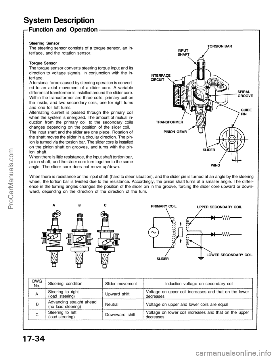
System Description
Function and Operation
Steering Sensor
The steering sensor consists of a torque sensor, an in-
terface, and the rotation sensor.
INPUT
SHAFT
TORSION BAR
SPIRAL
GROOVE
GUIDE
PIN
INTERFACE
CIRCUIT
Torque Sensor
The torque sensor converts steering torque input and its
direction to voltage signals, in conjunction with the in-
terface.
A torsional force caused by steering operation is convert-
ed to an axial movement of a slider core. A variable
differential transformer is installed around the slider core.
Within the tranceformer are three coils, primary coil on
the inside, and two secondary coils, one for right turns
and one for left turns.
Alternating current is passed through the primary coil
when the system is energized. The amount of mutual in-
duction from the primary coil to the secondary coils
changes depending on the position of the slider coil.
The input shaft and the slider are one piece. Rotation of
the shaft moves the slider in a circular direction. The pin-
ion is turned via the torsion bar. The slider core is installed
on the pinion shaft on grooves, and turns with the pin-
ion shaft.
When there is little resistance, the input shaft tortion bar,
pinion shaft, and the slider core turn together to the same
angle. The slider core does not move up/down.
When there is resistance on the input shaft (hard to steer situation), and the slider pin is turned at an angle by the steering
wheel, the tortion bar is twisted due to the resistance. Accordingly, the pinion shaft turns at a smaller angle. The differ-
ence in the turning angles changes the position of the slider pin in the groove, forcing the slider core upward or down-
ward, depending on the direction of the direction of the turn.
TRANSFORMER
PINION GEAR
SLIDER
WING
PRIMARY COIL
UPPER SECONDARY COIL
LOWER SECONDARY COIL
SLIDER
DWG
No.
A
B
C
Steering condition
Steering to right
(load steering)
Advancing straight ahead
(no load steering)
Steering to left
(load steering)
Slider movement
Upward shift
Neutral
Downward shift
Induction voltage on secondary coil
Voltage on upper coil increases and that on the lower
decreases
Voltage on upper and lower coils are equal
Voltage on lower coil increases and that on the upper
decreasesProCarManuals.com
Page 1328 of 1640
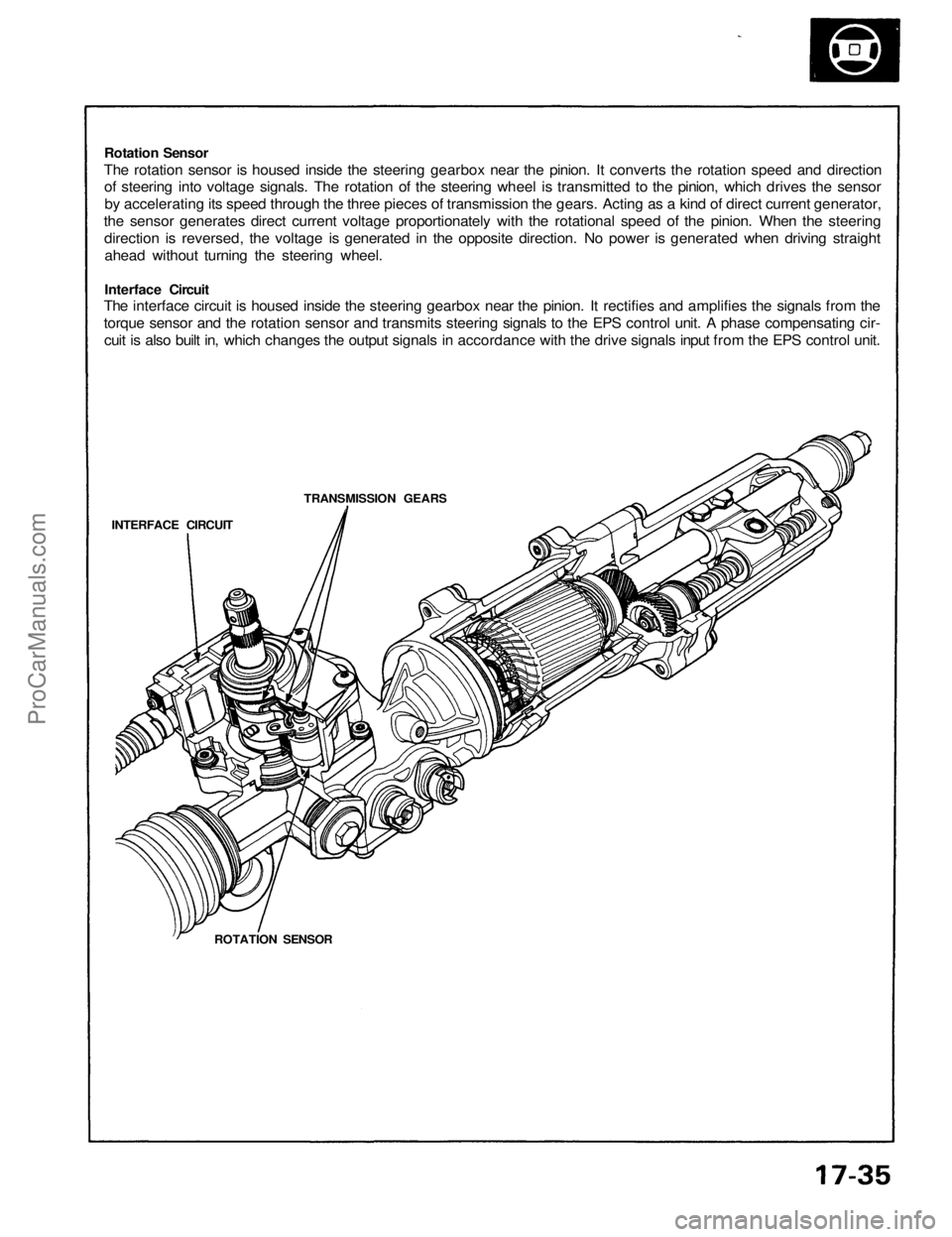
Rotation Sensor
The rotation sensor is housed inside the steering gearbox near the pinion. It converts the rotation speed and direction
of steering into voltage signals. The rotation of the steering wheel is transmitted to the pinion, which drives the sensor
by accelerating its speed through the three pieces of transmission the gears. Acting as a kind of direct current generator,
the sensor generates direct current voltage proportionately with the rotational speed of the pinion. When the steering
direction is reversed, the voltage is generated in the opposite direction. No power is generated when driving straight
ahead without turning the steering wheel.
Interface Circuit
The interface circuit is housed inside the steering gearbox near the pinion. It rectifies and amplifies the signals from the
torque sensor and the rotation sensor and transmits steering signals to the EPS control unit. A phase compensating cir-
cuit is also built in, which changes the output signals in accordance with the drive signals input from the EPS control unit.
TRANSMISSION GEARS
INTERFACE CIRCUIT
ROTATION SENSORProCarManuals.com