1991 ACURA NSX jump start
[x] Cancel search: jump startPage 769 of 1640
Charging System
Troubleshooting
Alternator/Regulator Test
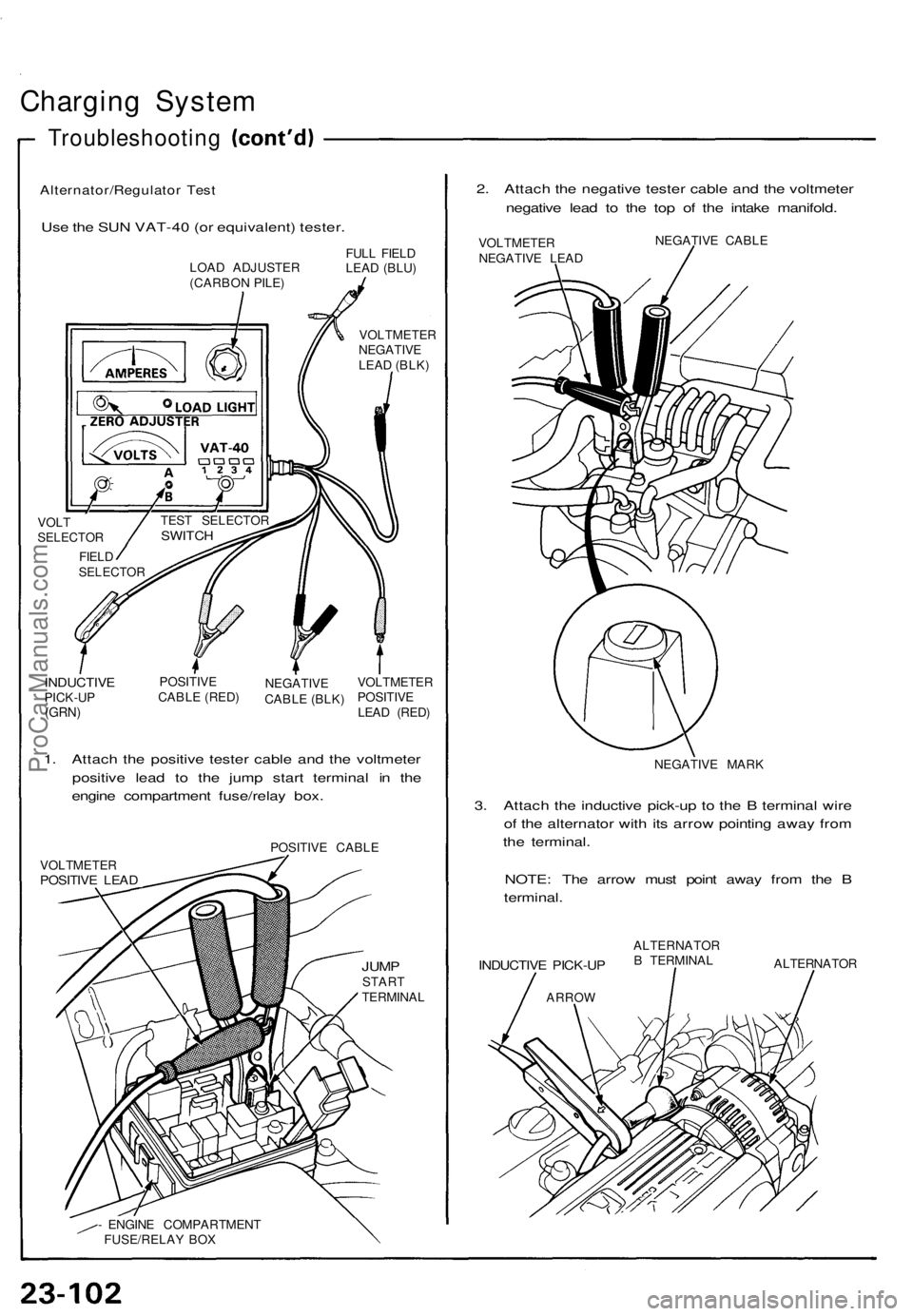
Use the SUN VAT-40 (or equivalent) tester.
2. Attach the negative tester cable and the voltmeter
negative lead to the top of the intake manifold.
LOAD ADJUSTER
(CARBON PILE)
FULL FIELD
LEAD (BLU)
VOLTMETER
NEGATIVE
LEAD (BLK)
VOLT
SELECTOR
FIELD
SELECTOR
INDUCTIVE
PICK-UP
(GRN)
POSITIVE
CABLE (RED)
NEGATIVE
CABLE (BLK)
VOLTMETER
POSITIVE
LEAD (RED)
1. Attach the positive tester cable and the voltmeter
positive lead to the jump start terminal in the
engine compartment fuse/relay box.
POSITIVE CABLE
VOLTMETER
POSITIVE LEAD
JUMP
START
TERMINAL
- ENGINE COMPARTMENT
FUSE/RELAY BOX
VOLTMETER
NEGATIVE LEAD
NEGATIVE CABLE
NEGATIVE MARK
3. Attach the inductive pick-up to the B terminal wire
of the alternator with its arrow pointing away from
the terminal.
NOTE: The arrow must point away from the B
terminal.
INDUCTIVE PICK-UP
ARROW
ALTERNATOR
B TERMINAL
ALTERNATOR
TEST SELECTOR
SWITCHProCarManuals.com
Page 795 of 1640
Fuel Gaug e
Gauge Tes t
1. Befor e testing , chec k th e No . 5 (1 5 A ) fus e i n th e
under-das h fus e box .
2 . Remov e th e rea r bulkhea d pane l behin d th e driver' s
seat , the n remov e th e acces s panel .
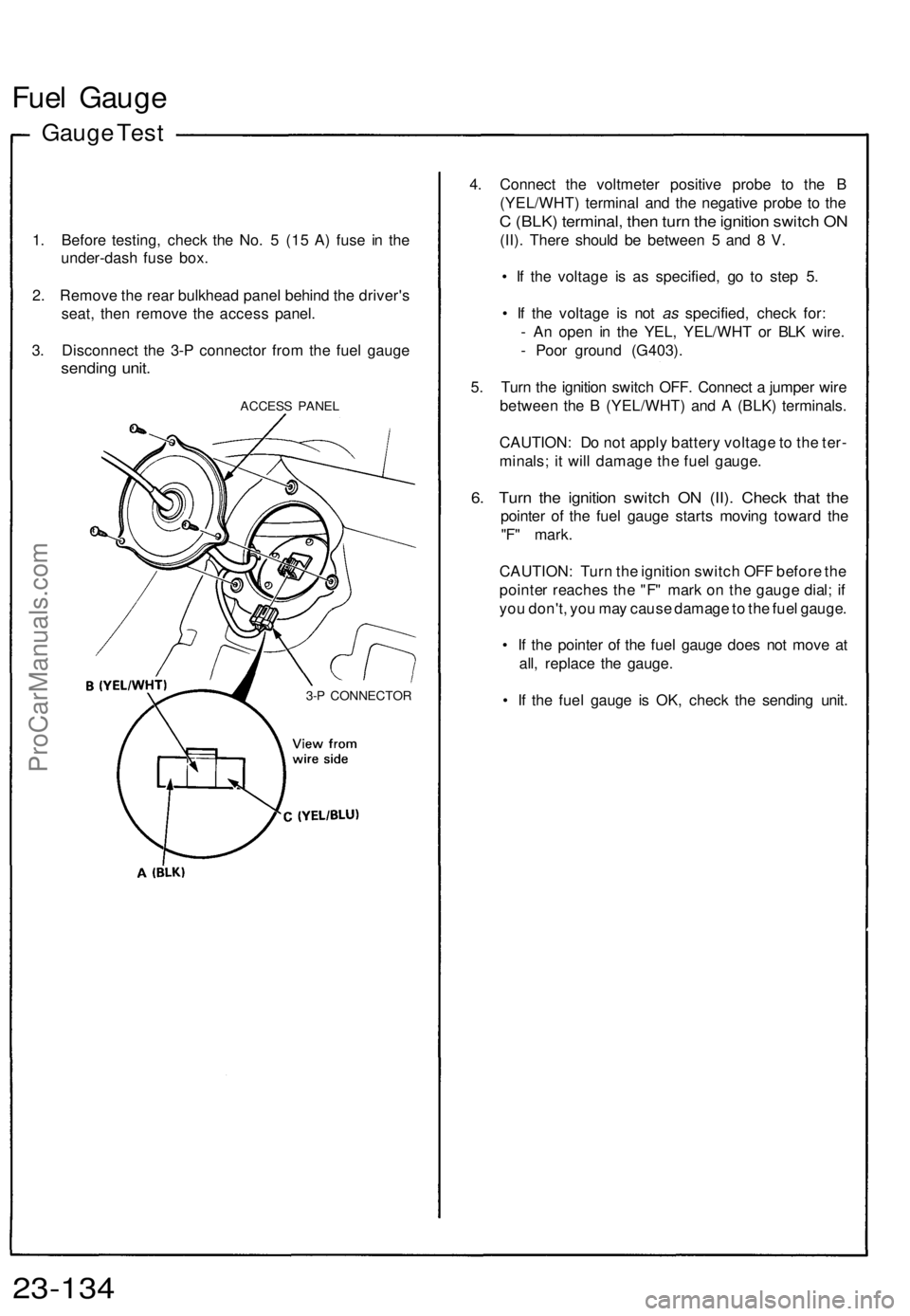
3 . Disconnec t th e 3- P connecto r fro m th e fue l gaug e
sendin g unit .
ACCES S PANE L
4. Connec t th e voltmete r positiv e prob e t o th e B
(YEL/WHT ) termina l an d th e negativ e prob e t o th e
C (BLK ) terminal , the n tur n th e ignitio n switc h O N
(II) . Ther e shoul d b e betwee n 5 an d 8 V .
• I f th e voltag e i s a s specified , g o t o ste p 5 .
• I f th e voltag e i s no t as specified , chec k for :
- A n ope n i n th e YEL , YEL/WH T o r BL K wire .
- Poo r groun d (G403) .
5 . Tur n th e ignitio n switc h OFF . Connec t a jumpe r wir e
betwee n th e B (YEL/WHT ) an d A (BLK ) terminals .
CAUTION : D o no t appl y batter y voltag e to th e ter -
minals ; i t wil l damag e th e fue l gauge .
6. Tur n th e ignitio n switc h O N (II) . Chec k tha t th e
pointe r o f th e fue l gaug e start s movin g towar d th e
"F " mark .
CAUTION : Tur n th e ignitio n switc h OF F befor e th e
pointe r reache s th e "F " mar k o n th e gaug e dial ; i f
yo u don't , yo u ma y caus e damag e to th e fue l gauge .
• I f th e pointe r o f th e fue l gaug e doe s no t mov e a t
all , replac e th e gauge .
• I f th e fue l gaug e i s OK , chec k th e sendin g unit .
23-13 4
3-P CONNECTO R
ProCarManuals.com
Page 797 of 1640
Engine Coolan t Temperatur e (ECT ) Gaug e
ECT Gaug e Tes t
1. Befor e testing , chec k th e No . 5 (1 5 A ) fus e i n th e
under-das h fus e box .
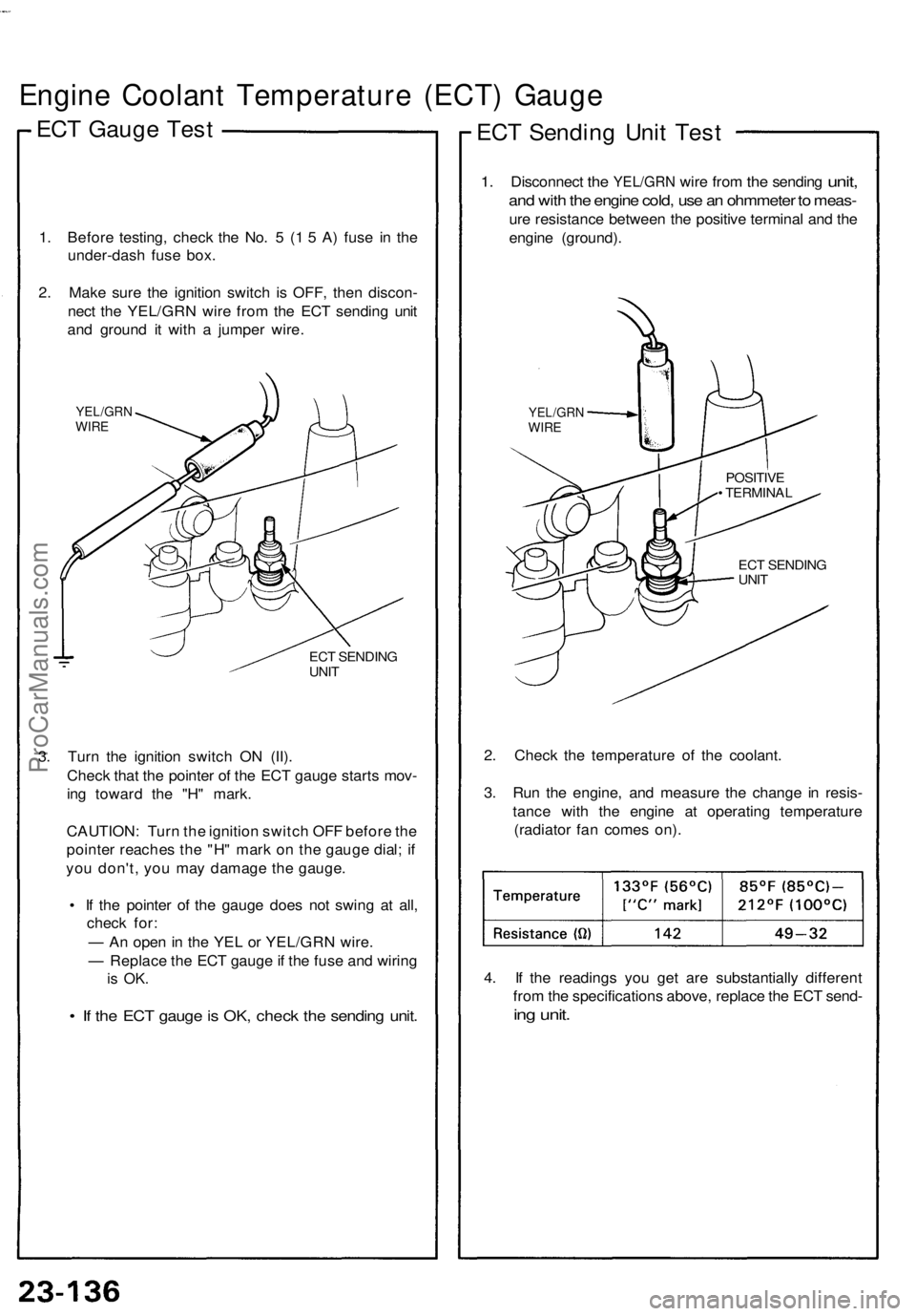
2 . Mak e sur e th e ignitio n switc h i s OFF , the n discon -
nec t th e YEL/GR N wir e fro m th e EC T sendin g uni t
an d groun d i t wit h a jumpe r wire .
YEL/GR NWIRE
ECT SENDIN G
UNI T
3. Tur n th e ignitio n switc h O N (II) .
Chec k tha t th e pointe r o f th e EC T gaug e start s mov -
in g towar d th e "H " mark .
CAUTION : Tur n th e ignitio n switc h OF F befor e th e
pointe r reache s th e "H " mar k o n th e gaug e dial ; i f
yo u don't , yo u ma y damag e th e gauge .
• I f th e pointe r o f th e gaug e doe s no t swin g a t all ,
chec k for :
— A n ope n in th e YE L o r YEL/GR N wire .
— Replac e th e EC T gaug e if th e fus e an d wirin g
is OK .
• I f th e EC T gaug e is OK , chec k th e sendin g unit .
ECT Sendin g Uni t Tes t
1. Disconnec t the YEL/GR N wire fro m the sendin g unit,
and wit h th e engin e cold , us e a n ohmmete r t o meas -
ure resistanc e betwee n th e positiv e termina l an d th e
engin e (ground) .
2 . Chec k th e temperatur e o f th e coolant .
3 . Ru n th e engine , an d measur e th e chang e i n resis -
tanc e wit h th e engin e a t operatin g temperatur e
(radiato r fa n come s on) .
4 . I f th e reading s yo u ge t ar e substantiall y differen t
fro m th e specification s above , replac e th e EC T send -
ing unit .
YEL/GR NWIRE
POSITIV E
• TERMINA L
EC T SENDIN G
UNI T
ProCarManuals.com
Page 798 of 1640
Engine Oi l Pressur e Gaug e
Gauge Tes t
1. Befor e testing , chec k th e No . 5 (1 5 A ) fus e i n th e
under-das h fus e box .
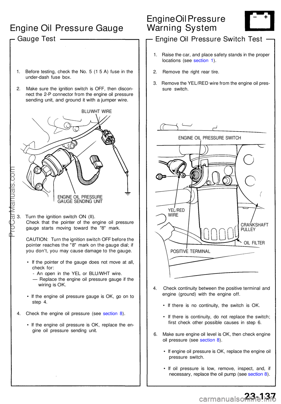
2 . Mak e sur e th e ignitio n switc h i s OFF , the n discon -
nec t th e 2- P connecto r fro m th e engin e oi l pressur e
sending unit , an d groun d it wit h a jumpe r wire .
BLU/WH T WIR E
ENGIN E OI L PRESSUR EGAUGE SENDIN G UNI T
3. Tur n th e ignitio n switc h O N (II) .
Chec k tha t th e pointe r o f th e engin e oi l pressur e
gaug e start s movin g towar d th e "8 " mark .
CAUTION : Tur n th e ignitio n switc h OF F befor e th e
pointe r reache s th e "8 " mar k o n th e gaug e dial ; i f
yo u don't , yo u ma y caus e damag e t o th e gauge .
• I f th e pointe r o f th e gaug e doe s no t mov e a t all ,
chec k for :
- A n ope n i n th e YE L o r BLU/WH T wire .
— Replac e th e engin e oi l pressur e gaug e i f th e
wirin g is OK .
• I f th e engin e oi l pressur e gaug e i s OK , g o o n t o
ste p 4 .
4 . Chec k th e engin e oi l pressur e (se e sectio n 8 ).
• I f th e engin e oi l pressur e i s OK , replac e th e en -
gin e oi l pressur e sendin g unit .
Engin e Oi l Pressur e
Warnin g Syste m
Engine Oi l Pressur e Switc h Tes t
1. Rais e th e car , an d plac e safet y stand s in th e prope r
location s (se e sectio n 1 ).
2 . Remov e th e righ t rea r tire .
3 . Remov e th e YEL/RE D wir e fro m th e engin e oi l pres -
sur e switch .
ENGINE OI L PRESSUR E SWITC H
CRANKSHAF TPULLEY
4. Chec k continuit y betwee n th e positiv e termina l an d
engin e (ground ) wit h th e engin e off .
• I f ther e i s n o continuity , th e switc h i s OK .
• I f ther e i s continuity , d o no t replac e th e switch ;
firs t chec k othe r possibl e cause s i n ste p 6 .
6 . Mak e sur e engin e oi l leve l i s OK , the n chec k engine
oi l pressur e (se e sectio n 8 ).
• I f engin e oi l pressur e is OK , replac e th e engin e oi l
pressur e switch .
• I f oi l pressur e i s low , remove , inspect , and , i f
necessary , replac e th e oi l pum p (se e sectio n 8 ).
YEL/RE DWIRE
POSITIV E TERMINA L
OIL FILTE R
ProCarManuals.com
Page 1076 of 1640
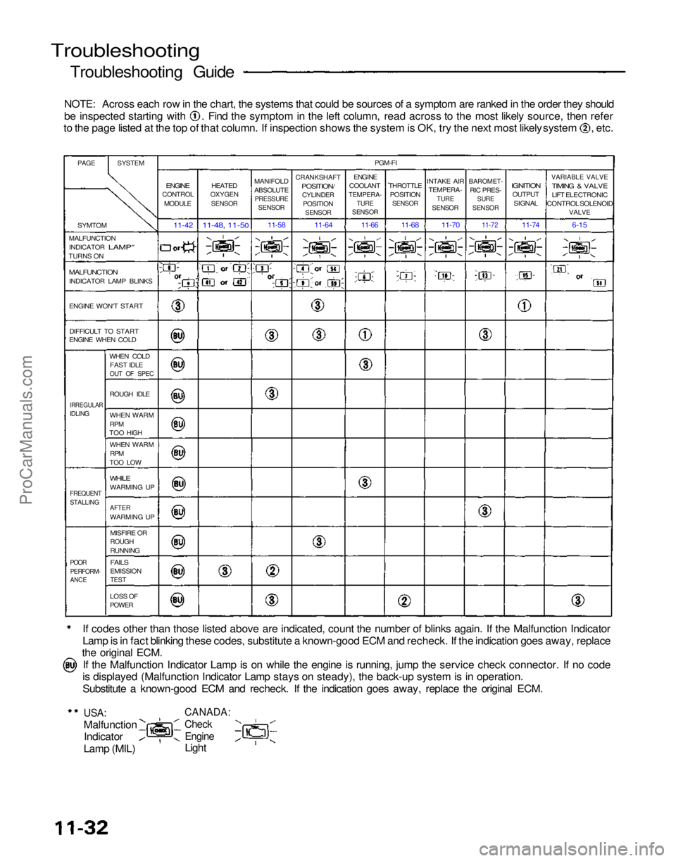
Troubleshooting
Troubleshooting Guide
NOTE: Across each row in the chart, the systems that could be sources of a symptom are ranked in the order they should be inspected starting with . Find the symptom in the left column, read across to the most likely source, then refer
to the page listed at the top of that column. If inspection shows the system is OK, try the next most likely system , etc.
If codes other than those listed above are indicated, count the number of blinks again. If the Malfunction Indicator
Lamp is in fact blinking these codes, substitute a known-good ECM and recheck. If the indication goes away, replace
the original ECM.
If the Malfunction Indicator Lamp is on while the engine is running, jump the service check connector. If no code
is displayed (Malfunction Indicator Lamp stays on steady), the back-up system is in operation.
Substitute a known-good ECM and recheck. If the indication goes away, replace the original ECM.
USA:
Malfunction
Indicator
Lamp (MIL)
CANADA:
Check
Engine
Light
PAGE
SYSTEM
SYMTOM
MALFUNCTION INDICATOR
LAMP"
TURNS ON
MALFUNCTION
INDICATOR LAMP BLINKS
ENGINE WON'T START
DIFFICULT TO START
ENGINE WHEN COLD
WHEN COLDFAST IDLE
OUT OF SPEC
IRREGULAR
IDLING
ROUGH IDLE
WHEN WARM
RPM
TOO HIGH
WHEN WARM
RPM
TOO LOW
WHILE
WARMING UP
FREQUENT
STALLING
AFTER
WARMING UP
MISFIRE OR
ROUGH
RUNNING
POOR
PERFORM-
ANCE
FAILS
EMISSION
TEST
LOSS OF
POWER
ENGINE
CONTROL
MODULE
11-42
HEATED
OXYGEN
SENSOR
11-48, 11-50
MANIFOLD
ABSOLUTE
PRESSURE
SENSOR
11-58
CRANKSHAFT
POSITION/
CYLINDER
POSITION
SENSOR
11-64
PGM-FI
ENGINE
COOLANT
TEMPERA-
TURE
SENSOR
THROTTLE
POSITION
SENSOR
INTAKE AIR
TEMPERA-
TURE
SENSOR
BAROMET-
RIC PRES-
SURE
SENSOR
IGNITION
OUTPUT
SIGNAL
VARIABLE VALVE
TIMING & VALVE
LIFT ELECTRONIC
CONTROL SOLENOID
VALVE
6-15
11-74
11-72
11-70
11-68
11-66
ProCarManuals.com
Page 1088 of 1640
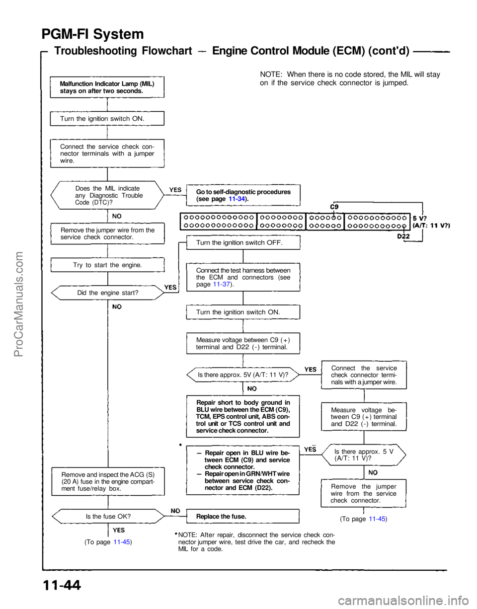
PGM-FI System
Troubleshooting Flowchart
Engine Control Module (ECM) (cont'd)
Malfunction Indicator Lamp (MIL) stays on after two seconds.
Turn the ignition switch ON.
Connect the service check con-
nector terminals with a jumper
wire.
Does the MIL indicate
any Diagnostic Trouble
Code (DTC)?
Remove the jumper wire from the
service check connector.
Try to start the engine.Did the engine start?
Remove and inspect the ACG (S) (20 A) fuse in the engine compart-
ment fuse/relay box.
Is the fuse OK?
(To page 11-45) Go to self-diagnostic procedures
(see page 11-34).
Turn the ignition switch OFF.
Connect the test harness between
the ECM and connectors (see page 11-37).
Turn the ignition switch ON.
Measure voltage between C9 (+)
terminal and D22 (-) terminal.
Is there approx. 5V (A/T: 11 V)?
Repair short to body ground in
BLU wire between the ECM (C9),
TCM, EPS control unit, ABS con-
trol unit or TCS control unit and service check connector.
Repair open in BLU wire be-
tween ECM (C9) and service check connector.
Repair open in GRN/WHT wire
between service check con-
nector and ECM (D22).
Replace the fuse.
NOTE: After repair, disconnect the service check con-
nector jumper wire, test drive the car, and recheck the
MIL for a code. NOTE: When there is no code stored, the MIL will stay
on if the service check connector is jumped.
Connect the service
check connector termi-
nals with a jumper wire.
Measure voltage be-
tween C9 (+) terminal
and D22 (-) terminal.
Is there approx. 5 V(A/T:
11 V)?
Remove the jumper
wire from the service
check connector.
(To page 11-45)ProCarManuals.com
Page 1122 of 1640
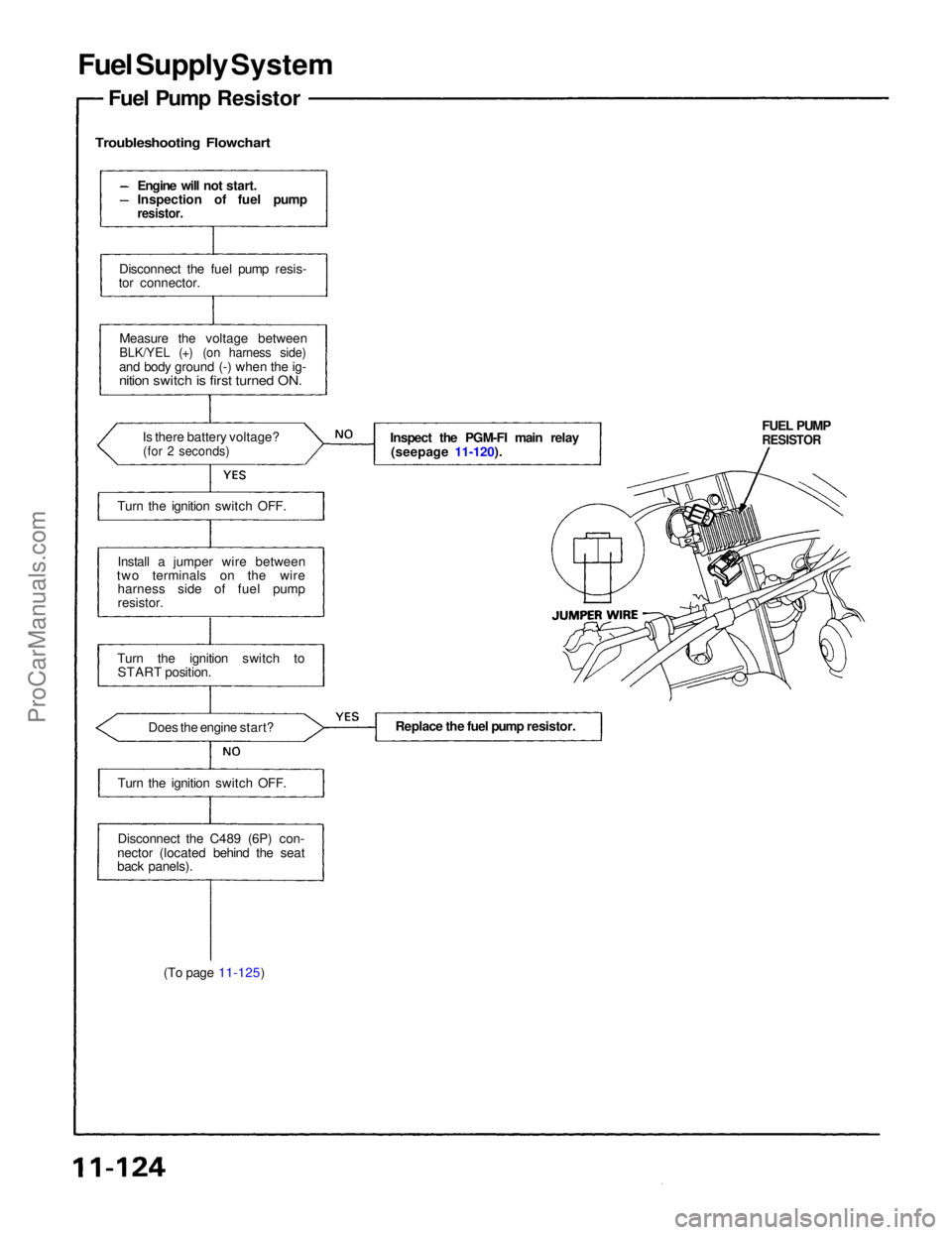
Fuel Supply System
Fuel Pump Resistor
Troubleshooting Flowchart
(To page 11-125) FUEL PUMP
RESISTOR
Inspect the PGM-FI main relay
(seepage 11-120).
Engine will not start.
Inspection of fuel pump
resistor.
Disconnect the fuel pump resis-
tor connector.
Measure the voltage between
BLK/YEL (+) (on harness side)
and body ground (-) when the ig-
nition switch is first turned ON.
Is there battery voltage?
(for 2 seconds)
Turn the ignition switch OFF.
Install a jumper wire between
two terminals on the wire harness side of fuel pump
resistor.
Turn the ignition switch to START position.
Does the engine start?
Turn the ignition switch OFF.
Disconnect the C489 (6P) con-
nector (located behind the seat
back panels). Replace the fuel pump resistor.ProCarManuals.com
Page 1148 of 1640
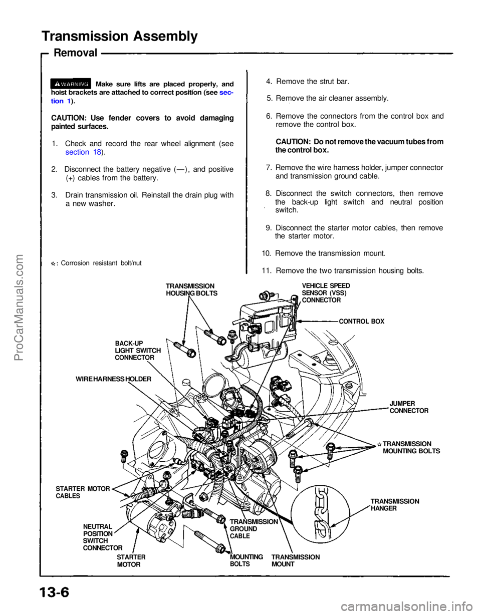
Transmission Assembly
Removal
CAUTION: Use fender covers to avoid damaging
painted surfaces.
1. Check and record the rear wheel alignment (see section 18).
2. Disconnect the battery negative (—), and positive (+) cables from the battery.
3. Drain transmission oil. Reinstall the drain plug with a new washer.
Corrosion resistant bolt/nut 4. Remove the strut bar.
5. Remove the air cleaner assembly.
6. Remove the connectors from the control box and remove the control box.
CAUTION: Do not remove the vacuum tubes from
the control box.
7. Remove the wire harness holder, jumper connector and transmission ground cable.
8. Disconnect the switch connectors, then remove the back-up light switch and neutral positionswitch.
9. Disconnect the starter motor cables, then remove the starter motor.
10. Remove the transmission mount.
11. Remove the two transmission housing bolts.
TRANSMISSION HOUSING BOLTS
BACK-UP
LIGHT SWITCH
CONNECTOR
WIRE HARNESS HOLDER
STARTER MOTOR
CABLES
NEUTRAL
POSITION
SWITCH
CONNECTOR
STARTER
MOTOR
TRANSMISSION
GROUND
CABLE
TRANSMISSION
MOUNT
MOUNTING
BOLTS
TRANSMISSION
HANGER
TRANSMISSION
MOUNTING BOLTS
JUMPER
CONNECTOR
VEHICLE SPEED
SENSOR (VSS)
CONNECTOR
CONTROL BOX
Make sure lifts are placed properly, and
hoist brackets are attached to correct position (see sec-
tion 1).ProCarManuals.com