Page 439 of 1640
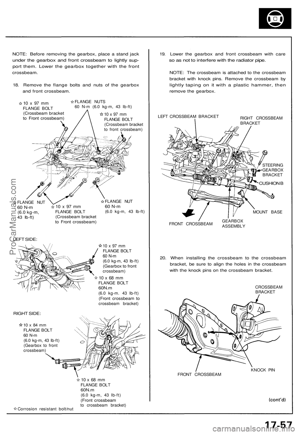
NOTE: Before removing the gearbox, place a stand jack
under the gearbox and front crossbeam to lightly sup-
port them. Lower the gearbox together with the front
crossbeam.
18. Remove the flange bolts and nuts of the gearbox
and front crossbeam.
10 x 97 mm
FLANGE BOLT
(Crossbeam bracket
to Front crossbeam)
FLANGE NUTS
60 N-m (6.0 kg-m, 43 Ib-ft)
10 x 97 mm
FLANGE BOLT
(Crossbeam bracket
to front crossbeam)
/
FLANGE NUT
60 N-m
(6.0 kg-m,
43 Ib-ft)
LEFT SIDE:
10 x 97 mm
FLANGE BOLT
(Crossbeam bracket
to Front crossbeam)
FLANGE NUT
60 N-m
(6.0 kg-m, 43 Ib-ft)
10 x 97 mm
FLANGE BOLT
60 N-m
(6.0 kg-m, 43 Ib-ft)
(Gearbox to front
crossbeam)
10 x 68 mm
FLANGE BOLT
60N.m
(6.0 kg-m. 43 Ib-ft)
(Front crossbeam to
crossbeam bracket)
RIGHT SIDE:
10 x 84 mm
FLANGE BOLT
60 N-m
(6.0 kg-m, 43 Ib-ft)
(Gearbox to front
crossbeam)
Corrosion resistant bolt/nut
10 x 68 mm
FLANGE BOLT
60N.m
(6.0 kg-m, 43 Ib-ft)
(Front crossbeam
to crossbeam bracket)
19. Lower the gearbox and front crossbeam with care
so as not to interfere with the radiator pipe.
NOTE: The crossbeam is attached to the crossbeam
bracket with knock pins. Remove the crossbeam by
lightly taping on it with a plastic hammer, then
remove the gearbox.
LEFT CROSSBEAM BRACKET
RIGHT CROSSBEAM
BRACKET
STEERING
GEARBOX
BRACKET
CUSHION B
MOUNT BASE
FRONT CROSSBEAM
GEARBOX
ASSEMBLY
20. When installing the crossbeam to the crossbeam
bracket, be sure to align the holes in the crossbeam
with the knock pins on the crossbeam bracket.
CROSSBEAM
BRACKET
FRONT CROSSBEAM
KNOCK PINProCarManuals.com
Page 441 of 1640
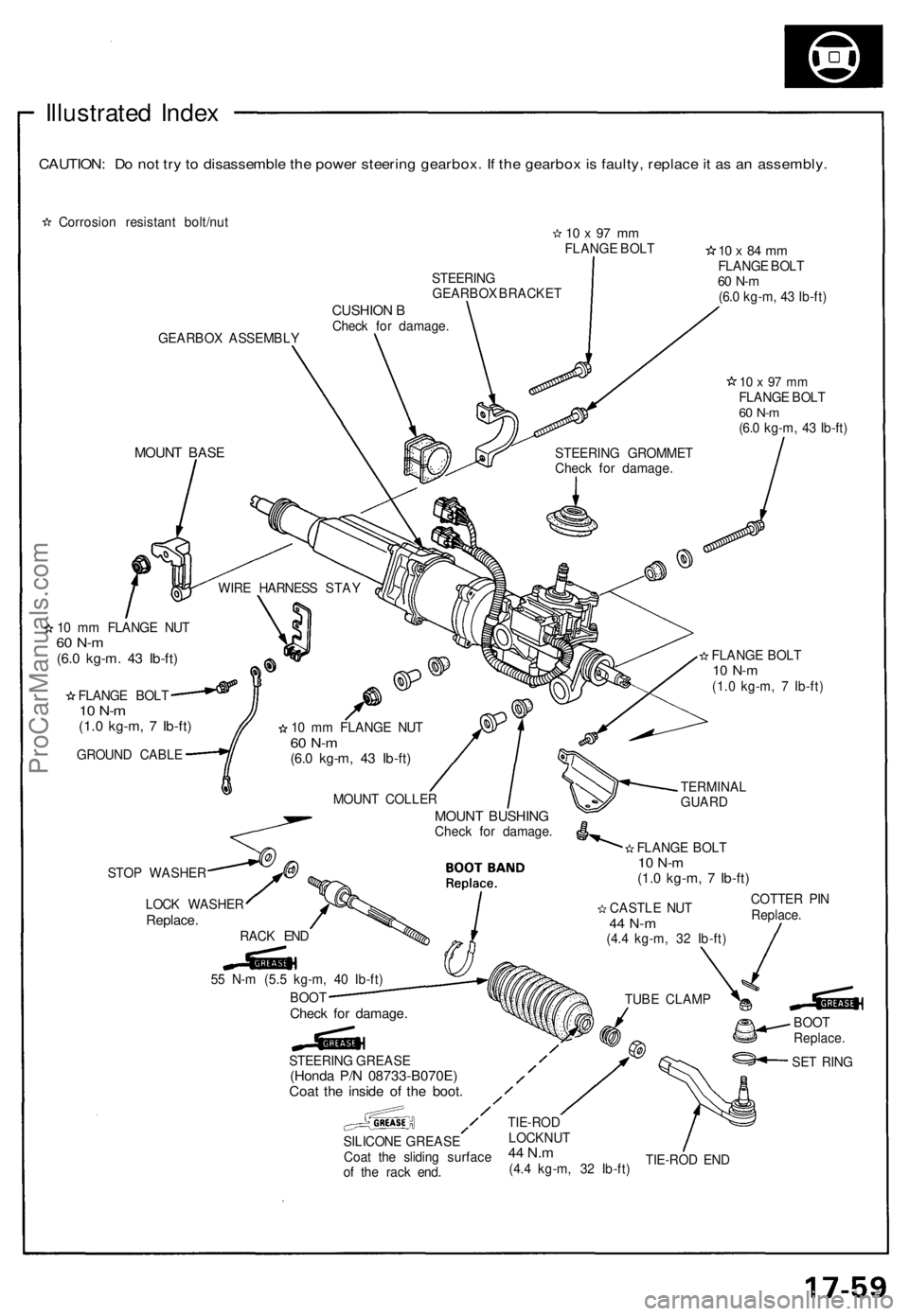
Illustrated Inde x
CAUTION : D o no t tr y to disassembl e th e powe r steerin g gearbox . I f th e gearbo x is faulty , replac e it a s a n assembly .
Corrosion resistan t bolt/nu t10 x 97 m mFLANG E BOL T
GEARBO X ASSEMBL Y STEERIN
G
GEARBO X BRACKE T
CUSHION BChec k fo r damage .
10 x 84 m mFLANG E BOL T60 N- m(6.0 kg-m , 4 3 Ib-ft )
10 x 97 m mFLANG E BOL T60 N- m(6.0 kg-m , 4 3 Ib-ft )
MOUN T BAS E
10 m m FLANG E NU T60 N- m(6.0 kg-m . 4 3 Ib-ft )
FLANG E BOL T10 N- m(1.0 kg-m , 7 Ib-ft )
GROUN D CABL E
STO P WASHE R
LOC K WASHE R
Replace.RACK EN D
TIE-ROD EN D
STEERIN
G GROMME T
Chec k fo r damage .
WIR E HARNES S STA Y
1 0 m m FLANG E NU T
60 N- m(6.0 kg-m , 4 3 Ib-ft )
FLANG E BOL T10 N- m(1.0 kg-m , 7 Ib-ft )
MOUN T COLLE R
MOUNT BUSHIN GCheck fo r damage .
FLANGE BOL T
10 N- m(1.0 kg-m , 7 Ib-ft )
TERMINA L
GUAR D
COTTE R PI N
Replace .
CASTL
E NU T
44 N- m(4.4 kg-m , 3 2 Ib-ft )
TUB E CLAM P
BOOT
Replace .
SE T RIN G
STEERIN
G GREAS E
(Honda P/ N 08733-B070E )Coat th e insid e o f th e boot .
SILICON E GREAS E
Coa t th e slidin g surfac e
o f th e rac k end .
TIE-RO DLOCKNU T44 N.m(4.4 kg-m , 3 2 Ib-ft )
5
5 N- m (5. 5 kg-m , 4 0 Ib-ft )
BOO T
Chec k fo r damage .
ProCarManuals.com
Page 442 of 1640
Steering Gearbo x
Inspectio n
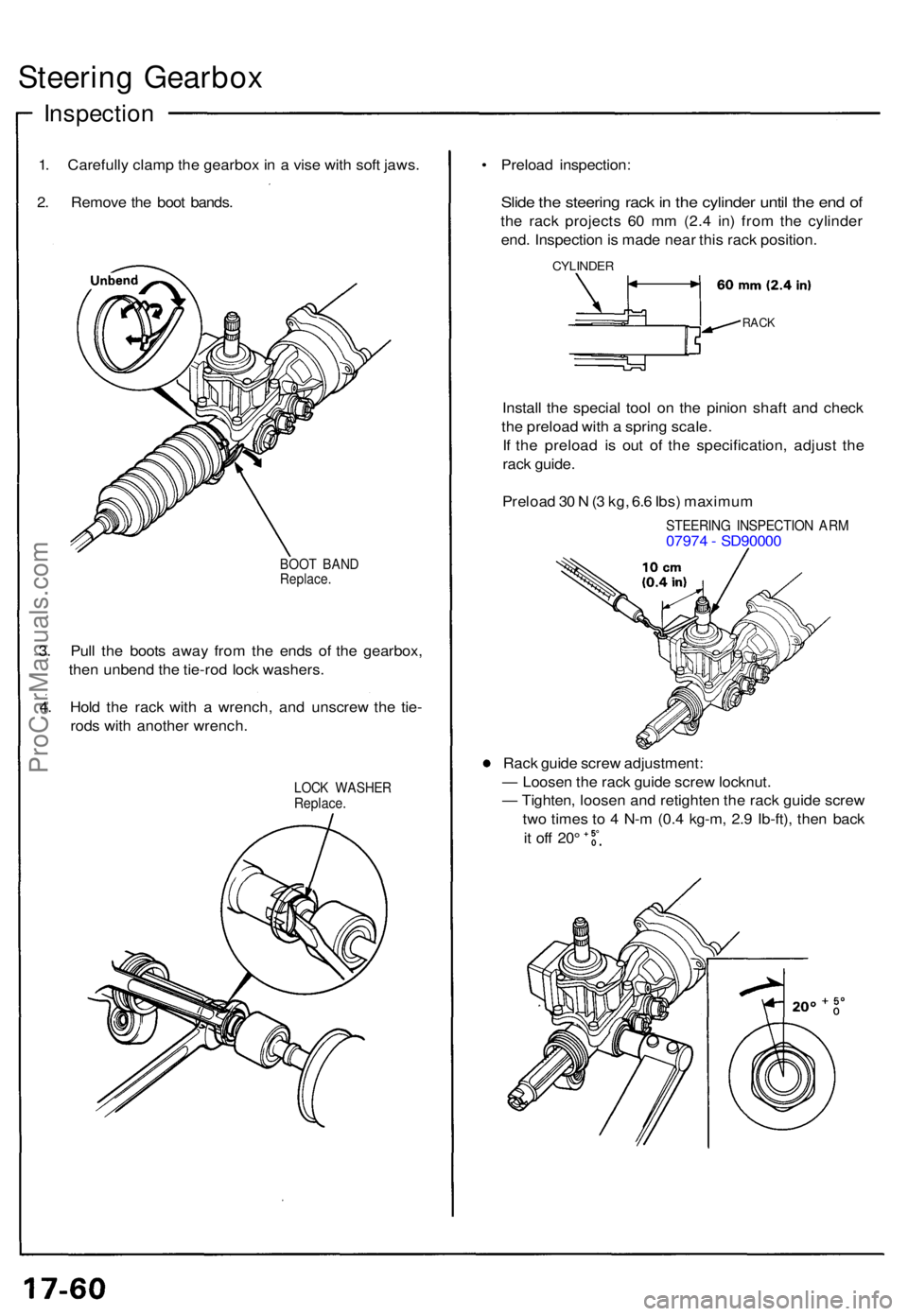
1. Carefull y clam p th e gearbo x i n a vis e wit h sof t jaws .
2 . Remov e th e boo t bands .
BOOT BAN DReplace .
3. Pul l th e boot s awa y fro m th e end s o f th e gearbox ,
the n unben d th e tie-ro d loc k washers .
4 . Hol d th e rac k wit h a wrench , an d unscre w th e tie -
rod s wit h anothe r wrench .
LOCK WASHE RReplace.
• Preloa d inspection :
Slide th e steerin g rac k in th e cylinde r unti l th e en d o f
th e rac k project s 6 0 m m (2. 4 in ) fro m th e cylinde r
end . Inspectio n is mad e nea r thi s rac k position .
CYLINDE R
RACK
Instal l th e specia l too l o n th e pinio n shaf t an d chec k
th e preloa d wit h a sprin g scale .
I f th e preloa d i s ou t o f th e specification , adjus t th e
rac k guide .
Preloa d 3 0 N (3 kg , 6. 6 Ibs ) maximu m
STEERIN G INSPECTIO N AR M0797 4 - SD9000 0
Rac k guid e scre w adjustment :
— Loose n th e rac k guid e scre w locknut .
— Tighten , loose n an d retighte n th e rac k guid e scre w
tw o time s t o 4 N- m (0. 4 kg-m , 2. 9 Ib-ft) , the n bac k
it of f 20 °
ProCarManuals.com
Page 973 of 1640
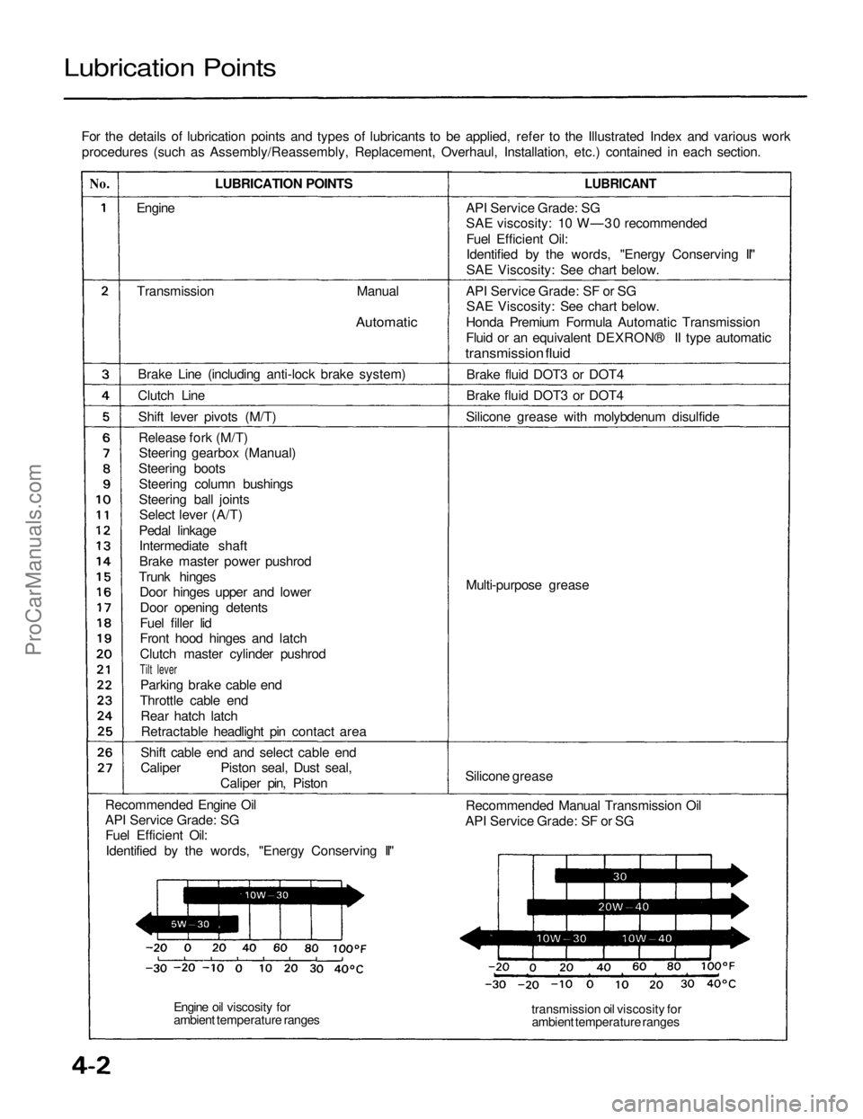
Lubrication Points
For the details of lubrication points and types of lubricants to be applied, refer to the Illustrated Index and various workprocedures (such as Assembly/Reassembly, Replacement, Overhaul, Installation, etc.) contained in each section.
No.
LUBRICATION POINTS
LUBRICANT
Engine
Transmission
Manual
Automatic
Brake Line (including anti-lock brake system)
Clutch Line Shift lever pivots (M/T)Release fork (M/T)Steering gearbox (Manual)
Steering boots Steering column bushings
Steering ball jointsSelect lever (A/T)
Pedal linkage Intermediate shaft
Brake master power pushrod
Trunk hinges Door hinges upper and lower
Door opening detents
Fuel filler lid
Front hood hinges and latch
Clutch master cylinder pushrod
Tilt lever
Parking brake cable end
Throttle cable end Rear hatch latchRetractable headlight pin contact area
Shift cable end and select cable end
Caliper Piston seal, Dust seal, Caliper pin, Piston
Recommended Engine Oil
API Service Grade: SG Fuel Efficient Oil:
Identified by the words, "Energy Conserving II" API Service Grade: SG
SAE viscosity: 10 W—30 recommended
Fuel Efficient Oil:
Identified by the words, "Energy Conserving II"
SAE Viscosity: See chart below.
API Service Grade: SF or SG SAE Viscosity: See chart below.
Honda Premium Formula Automatic Transmission
Fluid or an equivalent DEXRON® II type automatic
transmission fluid
Brake fluid DOT3 or DOT4
Brake fluid DOT3 or DOT4
Silicone grease with molybdenum disulfide
Multi-purpose grease
Silicone grease Recommended Manual Transmission Oil
API Service Grade: SF or SG
transmission oil viscosity forambient temperature ranges
Engine oil viscosity for
ambient temperature rangesProCarManuals.com
Page 1298 of 1640
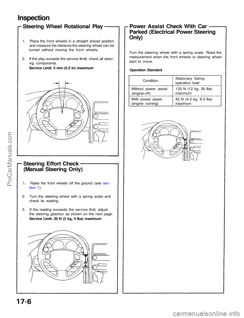
Inspection
Steering Wheel Rotational Play
1. Place the front wheels in a straight ahead position and measure the distance the steering wheel can be
turned without moving the front wheels.
2. If the
play
exceeds
the
service
limit,
check
all
steer- ing components.
Service Limit: 5 mm (0.2 in) maximum
Steering Effort Check (Manual Steering Only)
Operation Standard
Turn the steering wheel with a spring scale. Read the
measurement when the front wheels or steering wheel
start to move.Power Assist Check With Car
Parked (Electrical Power Steering
Only)
1. Raise the front wheels off the ground (see sec-
tion 1).
2. Turn the steering wheel with a spring scale and check its reading.
3. If the reading exceeds the service limit, adjust the steering gearbox as shown on the next page.
Service Limit: 20 N (2 kg, 4 Ibs) maximum Condition
Without power assist (engine off)
With power assist (engine running) Stationary Swing
operation load
120 N (12 kg, 26
Ibs)
maximum
42 N
(4.2
kg, 9.3
Ibs) maximumProCarManuals.com
Page 1299 of 1640
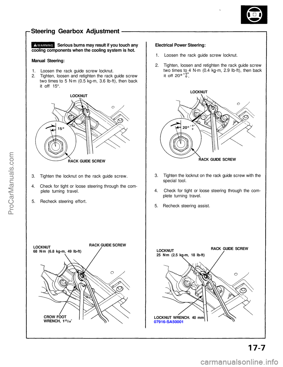
Steering Gearbox Adjustment
Serious burns may result if you touch any
cooling components when the cooling system is hot.
Manual Steering:
1. Loosen the rack guide screw locknut.
2. Tighten, loosen and retighten the rack guide screw
two times to 5 N .
m (0.5 kg-m, 3.6 Ib-ft), then back
it off
15°.
RACK GUIDE SCREW
3. Tighten the locknut on the rack guide screw.
4. Check for tight or loose steering through the com- plete turning travel.
5. Recheck steering effort.
RACK GUIDE SCREW
LOCKNUT
68 N ·
m (6.8 kg-m, 49 Ib-ft)
CROW FOOT LOCKNUT
Electrical Power Steering:
1. Loosen the rack guide screw locknut.
2. Tighten, loosen and retighten the rack guide screw two times to 4 N·m (0.4 kg-m, 2.9 Ib-ft), then back
LOCKNUT
RACK GUIDE SCREW
3. Tighten the locknut on the rack guide screw with the special tool.
4. Check for tight or loose steering through the com- plete turning travel.
5. Recheck steering assist.
LOCKNUT
25 N .
m (2.5 kg-m, 18 Ib-ft) RACK GUIDE SCREW
LOCKNUT WRENCH. 40 mm
07916-SA50001
it off 20
WRENCH,ProCarManuals.com
Page 1308 of 1640
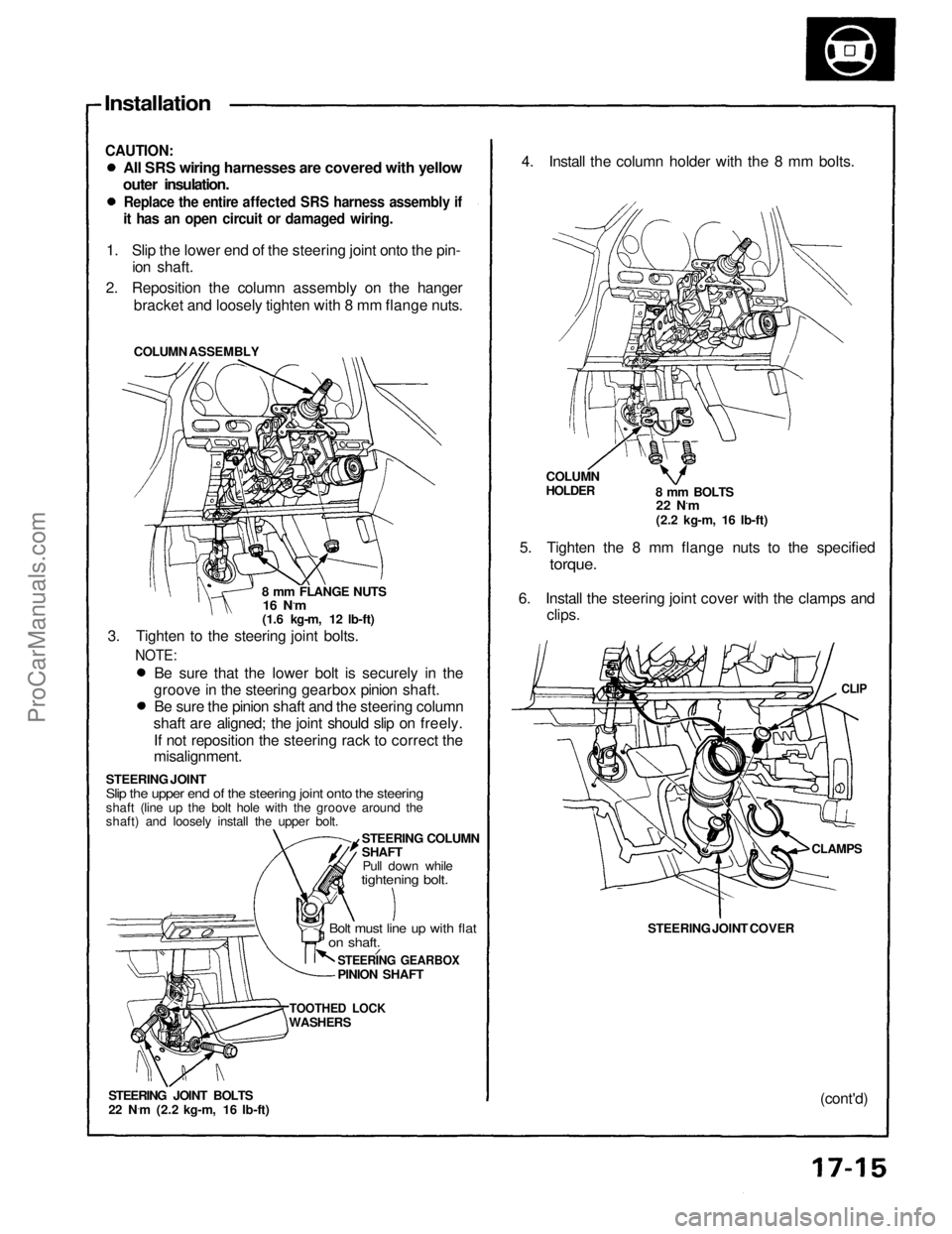
Installation
CAUTION:
All SRS wiring harnesses are covered with yellow
outer insulation.
Replace the entire affected SRS harness assembly if
it has an open circuit or damaged wiring.
1. Slip the lower end of the steering joint onto the pin- ion shaft.
2. Reposition the column assembly on the hanger bracket and loosely tighten with 8 mm flange nuts.
COLUMN ASSEMBLY
8 mm FLANGE NUTS
16 N.m
(1.6 kg-m, 12 lb-ft)
3. Tighten to the steering joint bolts.
NOTE:
Be sure that the lower bolt is securely in the
groove in the steering gearbox pinion shaft. Be sure the pinion shaft and the steering column
shaft are aligned; the joint should slip on freely.
If not reposition the steering rack to correct the
misalignment.
STEERING JOINT
Slip the upper end of the steering joint onto the steering
shaft (line up the bolt hole with the groove around the
shaft) and loosely install the upper bolt. STEERING COLUMN
SHAFTPull down while
tightening bolt.
Bolt must line up with flat
on shaft.
STEERING GEARBOX
PINION SHAFT
TOOTHED LOCK
WASHERS
STEERING JOINT BOLTS
22 N ·
m (2.2 kg-m, 16 Ib-ft) 4. Install the column holder with the 8 mm bolts.
COLUMN
HOLDER
8 mm BOLTS
22 N.m
(2.2 kg-m, 16 Ib-ft)
5. Tighten the 8 mm flange nuts to the specified
torque.
6. Install the steering joint cover with the clamps and clips.
CLIP
STEERING JOINT COVER
CLAMPS
(cont'd)ProCarManuals.com
Page 1311 of 1640
Component Location
Index
NOTE:
If an intact airbag assembly has been removed from a scrapped car or has been found defective or damaged during
transit, storage or service, it should be deployed (see section 23). Before removing the gearbox, remove the ignition key to lock the steering shaft from turning.
After installing the gearbox, check the wheel alignment and adjust if necessary.
STEERING WHEEL/AIRBAG ASSEMBLY
Removal, page 17-8
Disassembly, page 17-9
Installation, page 17-10
STEERING COLUMN
Removal, page 17-12
Inspection, page 17-14 Installation, page 17-15
STEERING GEARBOX
Removal/Installation, page 17-19 Disassembly, page 17-22
Inspection, page 17-21
Reassembly, page 17-25ProCarManuals.com