Page 1324 of 1640
System Description
Electrical Power Steering (EPS)
Outline
The NSX uses an electric motor-driven power steering, which possesses the characteristics best suited for a mid engine
automobile. This system is a power-assisted steering device, with a motor inside the steering gearbox driven by the EPS
control unit and power unit. Its distinctive features are described below:
ALTERNATOR
VEHICLE
SPEED SENSOR
STEERING WHEEL
EPS CONTROL UNIT
POWER UNIT
BATTERY
STEERING GEARBOX
STEERING
COLUMN
Minimized loss of engine horsepower and decreased fuel consumption.
A linear steering feel and the reduction of kickback.
The system is compact and lightweight because it requires no complicated hydraulic piping, etc.ProCarManuals.com
Page 1325 of 1640

FUSE BOX
System Description
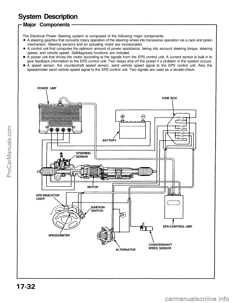
Major Components
The Electrical Power Steering system is composed of the following major components:
EPS CONTROL UNIT
COUNTERSHAFT
SPEED SENSOR
ALTERNATOR
SPEEDOMETER
EPS INDICATOR
LIGHT
STEERING
SENSOR
BATTERY
POWER UNIT
MOTOR
IGNITION
SWITCH
A steering gearbox that converts rotary operation of the steering wheel into transverse operation via a rack and pinion
mechanism. Steering sensors and an actuating motor are incorporated.
A control unit that computes the optimum amount of power assistance, taking into account steering torque, steering
speed, and vehicle speed. Selfdiagnosis functions are included.
A power unit that drives the motor according to the signals from the EPS control unit. A current sensor is built in to
give feedback information to the EPS control unit. Two relays shut off the power if a problem in the system occurs.
A speed sensor, the countershaft speed sensor, send vehicle speed signal to the EPS control unit. Also the
speedometer send vehicle speed signal to the EPS control unit. Two signals are used as a double-check.ProCarManuals.com
Page 1326 of 1640

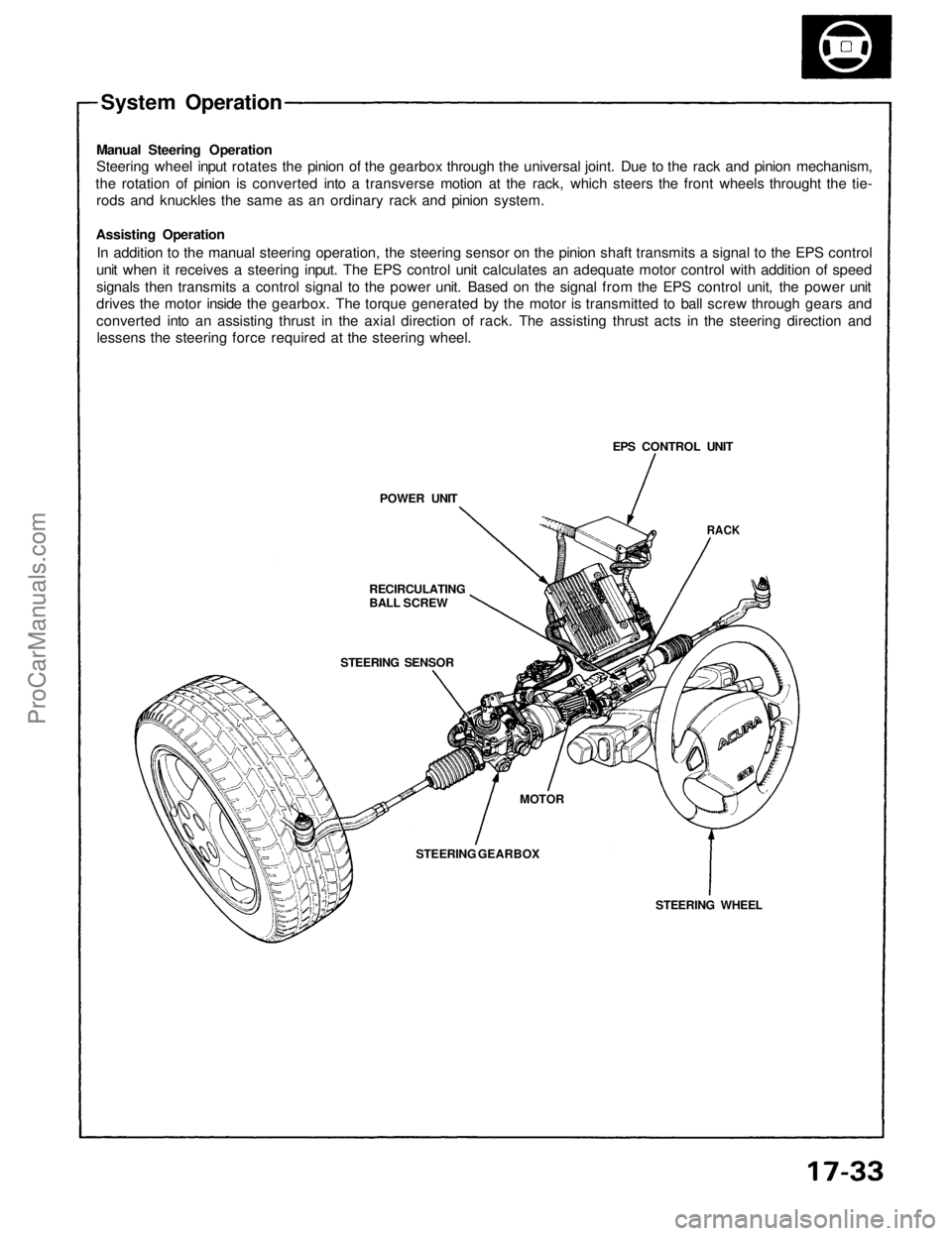
System Operation
Manual Steering Operation
Steering wheel input rotates the pinion of the gearbox through the universal joint. Due to the rack and pinion mechanism,
the rotation of pinion is converted into a transverse motion at the rack, which steers the front wheels throught the tie-
rods and knuckles the same as an ordinary rack and pinion system.
Assisting Operation
In addition to the manual steering operation, the steering sensor on the pinion shaft transmits a signal to the EPS control
unit when it receives a steering input. The EPS control unit calculates an adequate motor control with addition of speed
signals then transmits a control signal to the power unit. Based on the signal from the EPS control unit, the power unit
drives the motor inside the gearbox. The torque generated by the motor is transmitted to ball screw through gears and
converted into an assisting thrust in the axial direction of rack. The assisting thrust acts in the steering direction and
lessens the steering force required at the steering wheel.
POWER UNIT
RECIRCULATING
BALL SCREW
STEERING SENSOR
STEERING GEARBOX
MOTOR
STEERING WHEEL
RACK
EPS CONTROL UNITProCarManuals.com
Page 1328 of 1640

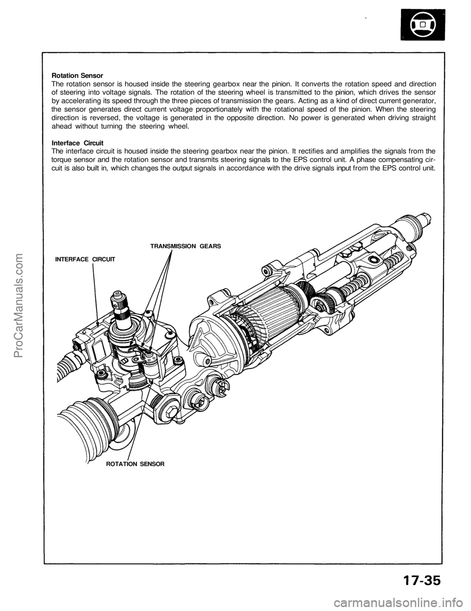
Rotation Sensor
The rotation sensor is housed inside the steering gearbox near the pinion. It converts the rotation speed and direction
of steering into voltage signals. The rotation of the steering wheel is transmitted to the pinion, which drives the sensor
by accelerating its speed through the three pieces of transmission the gears. Acting as a kind of direct current generator,
the sensor generates direct current voltage proportionately with the rotational speed of the pinion. When the steering
direction is reversed, the voltage is generated in the opposite direction. No power is generated when driving straight
ahead without turning the steering wheel.
Interface Circuit
The interface circuit is housed inside the steering gearbox near the pinion. It rectifies and amplifies the signals from the
torque sensor and the rotation sensor and transmits steering signals to the EPS control unit. A phase compensating cir-
cuit is also built in, which changes the output signals in accordance with the drive signals input from the EPS control unit.
TRANSMISSION GEARS
INTERFACE CIRCUIT
ROTATION SENSORProCarManuals.com
Page 1332 of 1640

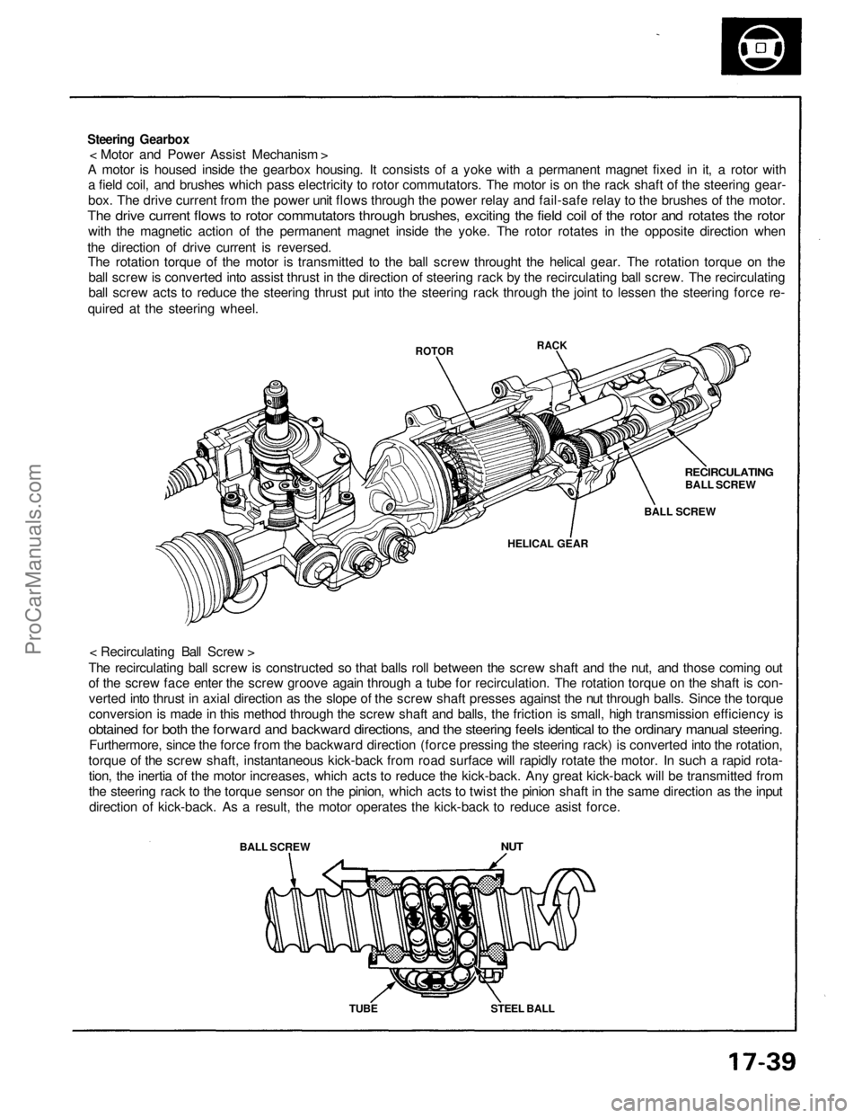
Steering Gearbox
< Motor and Power Assist Mechanism >
A motor is housed inside the gearbox housing. It consists of a yoke with a permanent magnet fixed in it, a rotor with
a field coil, and brushes which pass electricity to rotor commutators. The motor is on the rack shaft of the steering gear-
box. The drive current from the power unit flows through the power relay and fail-safe relay to the brushes of the motor.
The drive current flows to rotor commutators through brushes, exciting the field coil of the rotor and rotates the rotor
with the magnetic action of the permanent magnet inside the yoke. The rotor rotates in the opposite direction when
the direction of drive current is reversed.
The rotation torque of the motor is transmitted to the ball screw throught the helical gear. The rotation torque on the
ball screw is converted into assist thrust in the direction of steering rack by the recirculating ball screw. The recirculating
ball screw acts to reduce the steering thrust put into the steering rack through the joint to lessen the steering force re-
quired at the steering wheel.
< Recirculating Ball Screw >
The recirculating ball screw is constructed so that balls roll between the screw shaft and the nut, and those coming out
of the screw face enter the screw groove again through a tube for recirculation. The rotation torque on the shaft is con-
verted into thrust in axial direction as the slope of the screw shaft presses against the nut through balls. Since the torque
conversion is made in this method through the screw shaft and balls, the friction is small, high transmission efficiency is
obtained for both the forward and backward directions, and the steering feels identical to the ordinary manual steering.
Furthermore, since the force from the backward direction (force pressing the steering rack) is converted into the rotation,
torque of the screw shaft, instantaneous kick-back from road surface will rapidly rotate the motor. In such a rapid rota-
tion, the inertia of the motor increases, which acts to reduce the kick-back. Any great kick-back will be transmitted from
the steering rack to the torque sensor on the pinion, which acts to twist the pinion shaft in the same direction as the input
direction of kick-back. As a result, the motor operates the kick-back to reduce asist force.
BALL SCREW
ROTOR
NUT
TUBE
STEEL BALL
HELICAL GEAR
BALL SCREW
RECIRCULATING
BALL SCREW
RACKProCarManuals.com
Page 1333 of 1640
Wiring Locations
EPS CONTROL UNIT
MAIN RELAY BOX
POWER UNIT
TORQUE SENSOR 6-P CONNECTOR/
STEERING WHEEL SPEED SENSOR
4-P CONNECTOR
STEERING GEARBOX
(TORQUE SENSOR/STEERING WHEEL
SPEED SENSOR)
UNDER-DASH FUSE/RELAY BOX
TRANSMISSION CONTROL MODULE (TCM)
22-P CONNECTOR
VEHICLE SPEED SENSOR
(VSS)
ALTERNATOR 4-P CONNECTOR
EPS INDICATOR LIGHTProCarManuals.com
Page 1337 of 1640
Test Harness Installation
Test Harness A
EPS CONTROL UNIT
TEST HARNESS A
07MAZ-SL00100
Test Harness B
TEST HARNESS B
07MAZ-SL00200
STEERING GEARBOX
Test Harness C
POWER UNIT
TEST HARNESS C
07MAZ-SL00300
Power Unit Checker
Connect to the
cigarette lighter
POWER UNIT CHECKER
07MAZ-SL00400
POWER UNIT
OUTPUT
(VIS)
Remove the glove box and disconnect the EPS con-
trol unit connector.
Connect test harness A.
Disconnect the torque sensor and steering speed sen-
sor connectors and connect test harness B. Pull the floor carpet back from the passenger's side
and remove the bass speaker and power unit cover.
Disconnect the connector and connect test harness C.
Pull the floor carpet back from the passenger's side
and remove the bass speaker and power unit cover. Disconnect the connector and connect the power unit
checker.
Remove the cigarette lighter and connect the power
unit checker.ProCarManuals.com
Page 1339 of 1640
Component Location
Index
NOTE:
EPS CONTROL UNITReplacement, page 17-74
POWER UNIT
Replacement, page 17-73
STEERING WHEEL/
AIRBAG ASSEMBLYRemoval, page 17-8
Disassembly, page 17-9
Installation, page 17-10
STEERING COLUMN
Removal, page 17-12
Inspection, page 17-14
Installation, page 17-15
STEERING GEARBOX Removal/Installation, page 17-64
Illustrated Index, page 17-68
Pinion Preload Inspection, page 17-69
Rack Guide Screw Adjustment, page 17-69
If an intact airbag assembly has been removed from a scrapped car or has been found defective or damaged during
transit, storage or service, it should be deployed (see section 23).
Before removing the gearbox, remove the ignition key to lock the steering shaft.
After installing the gearbox, check the wheel alignment and adjust if necessary.ProCarManuals.com