1991 ACURA NSX coolant temperature
[x] Cancel search: coolant temperaturePage 1210 of 1640
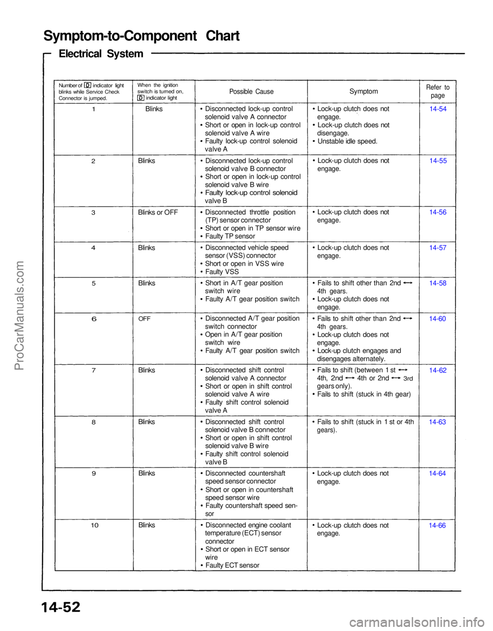
Symptom-to-Component Chart
Electrical System
Number of indicator light
blinks while Service Check
Connector is jumped.
When the ignition
switch is turned on,
indicator light
1
Blinks
Possible Cause
Symptom
Lock-up clutch does not
engage.
Lock-up clutch does not
disengage.
Unstable idle speed.
Refer to
page
14-54
14-55
14-56
14-57
14-58
14-60
14-62
14-63
14-64
14-66
Lock-up clutch does not
engage.
Lock-up clutch does not
engage.
Fails to shift (stuck in 1 st or 4th
gears).
Fails to shift other than 2nd
4th gears.
Lock-up clutch does not
engage.
Lock-up clutch engages and
disengages alternately. Fails to shift other than 2nd
4th gears.
Lock-up clutch does not
engage.
Lock-up clutch does not
engage.
Lock-up clutch does not
engage.
Lock-up clutch does not
engage.
Disconnected lock-up control
solenoid valve A connector Short or open in lock-up control
solenoid valve A wire
Faulty lock-up control solenoid
valve A
Disconnected lock-up control
solenoid valve B connector Short or open in lock-up control
solenoid valve B wire
Faulty lock-up control solenoid
valve B
Disconnected throttle position(TP) sensor connector
Short or open in TP sensor wire
Faulty TP sensor
Disconnected vehicle speed
sensor (VSS) connector
Short or open in VSS wire
Faulty VSS
Short in A/T gear position
switch wire
Faulty A/T gear position switch
Disconnected A/T gear position
switch connector
Open in A/T gear position
switch wire Faulty A/T gear position switch
Disconnected shift control
solenoid valve A connector Short or open in shift control
solenoid valve A wire
Faulty shift control solenoid
valve A
Disconnected shift control
solenoid valve B connector
Short or open in shift control
solenoid valve B wire
Faulty shift control solenoid
valve B
Disconnected countershaft
speed sensor connector
Short or open in countershaft
speed sensor wire Faulty countershaft speed sen-
sor
Disconnected engine coolant
temperature (ECT) sensor
connectorShort or open in ECT sensor
wire Faulty ECT sensor
Blinks
10
9
Blinks
Blinks
8
7
Blinks
6
OFF
Blinks
5
4
Blinks
3
Blinks or OFF Blinks
2
Fails to shift (between 1 st
4th,
2nd
4th or 2nd
3rd
gears only).
Fails to shift (stuck in 4th gear)ProCarManuals.com
Page 1221 of 1640
Road Test
NOTE:
Warm up the engine to normal operating temperature (the cooling fan comes on).
When the engine coolant temperature is below normal operating temperature, the shift point is higher than specifiedvehicle speed.
Range 1. Apply parking brake and block the wheels. Start the engine, then move the selector to while depressing the brake
pedal. Depress the accelerator pedal, and release it suddenly. Engine should not stall.
2. Check that shift points occur at approximate speeds shown. Also check for abnormal noise and clutch slippage.
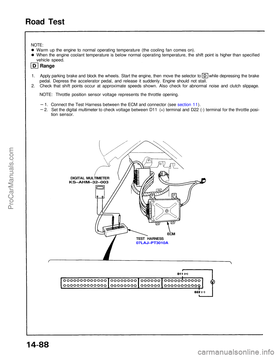
NOTE: Throttle position sensor voltage represents the throttle opening.
DIGITAL MULTIMETER
KS–AHM–32–003
ECM
TEST HARNESS
07LAJ–PT3010A
1. Connect the Test Harness between the ECM and connector (see section 11).
2. Set the digital multimeter to check voltage between D11 (+) terminal and D22 (-) terminal for the throttle posi- tion sensor.ProCarManuals.com
Page 1464 of 1640
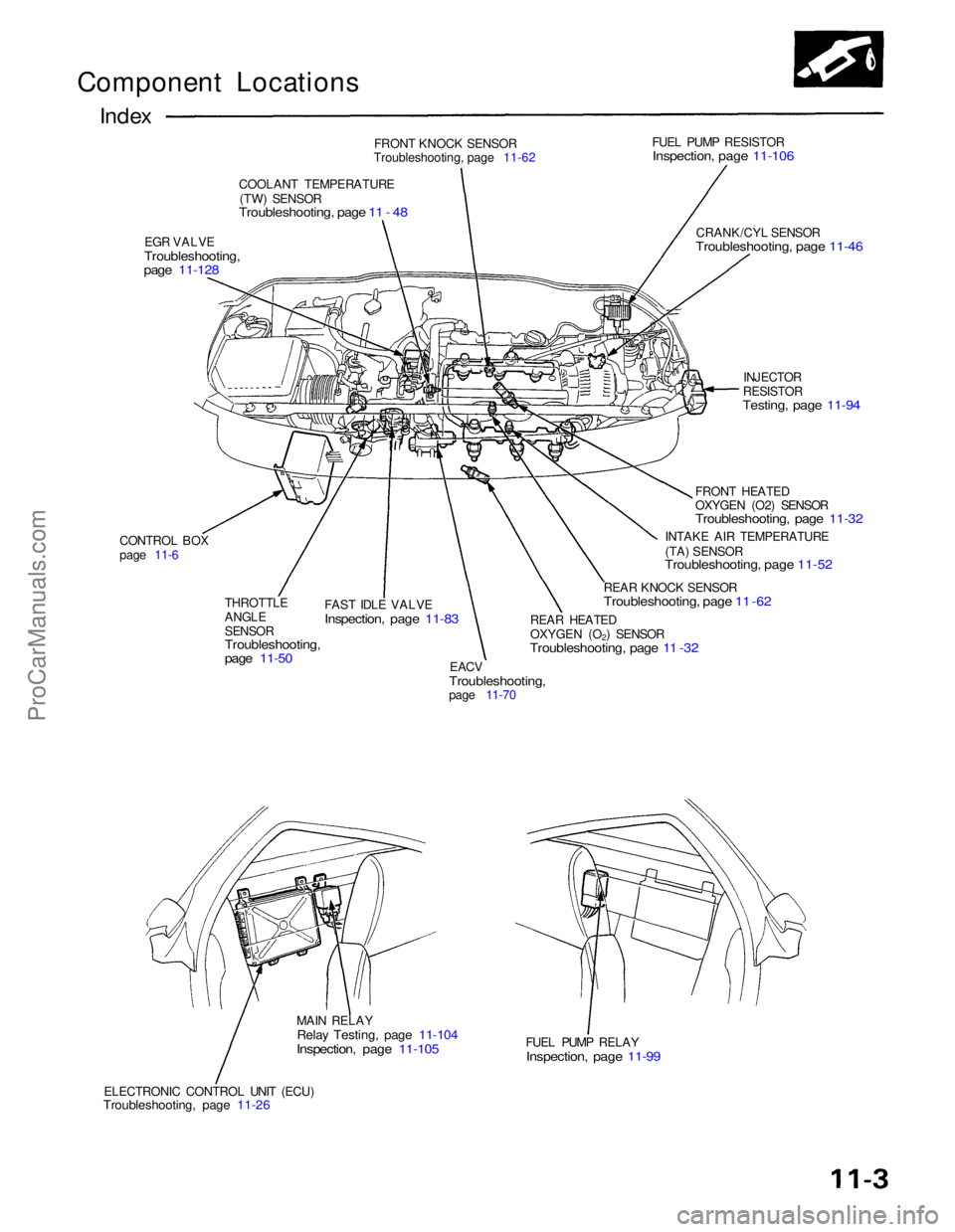
Component Locations
Index
FRONT KNOCK SENSOR
Troubleshooting, page 11-62
COOLANT TEMPERATURE (TW) SENSOR
Troubleshooting, page 11 - 48
EGR VALVE
Troubleshooting,
page 11-128
FUEL PUMP RESISTOR
Inspection, page 11-106
CRANK/CYL SENSOR
Troubleshooting, page 11-46
CONTROL BOX
page 11-6 THROTTLE
ANGLE
SENSOR
Troubleshooting,
page 11-50
FAST IDLE VALVE
Inspection, page 11-83
EACV
Troubleshooting,
page 11-70 INJECTOR
RESISTOR
Testing, page 11-94
FRONT HEATED
OXYGEN (O2) SENSOR
Troubleshooting, page 11-32
INTAKE AIR TEMPERATURE
(TA) SENSOR
Troubleshooting, page 11-52
REAR KNOCK SENSOR
Troubleshooting, page 11 -62
REAR HEATED
OXYGEN (O2) SENSOR
Troubleshooting, page 11 -32
MAIN RELAY
Relay Testing, page 11-104
Inspection, page 11-105
ELECTRONIC CONTROL UNIT (ECU)
Troubleshooting, page 11-26
FUEL PUMP RELAY
Inspection, page 11-99ProCarManuals.com
Page 1480 of 1640
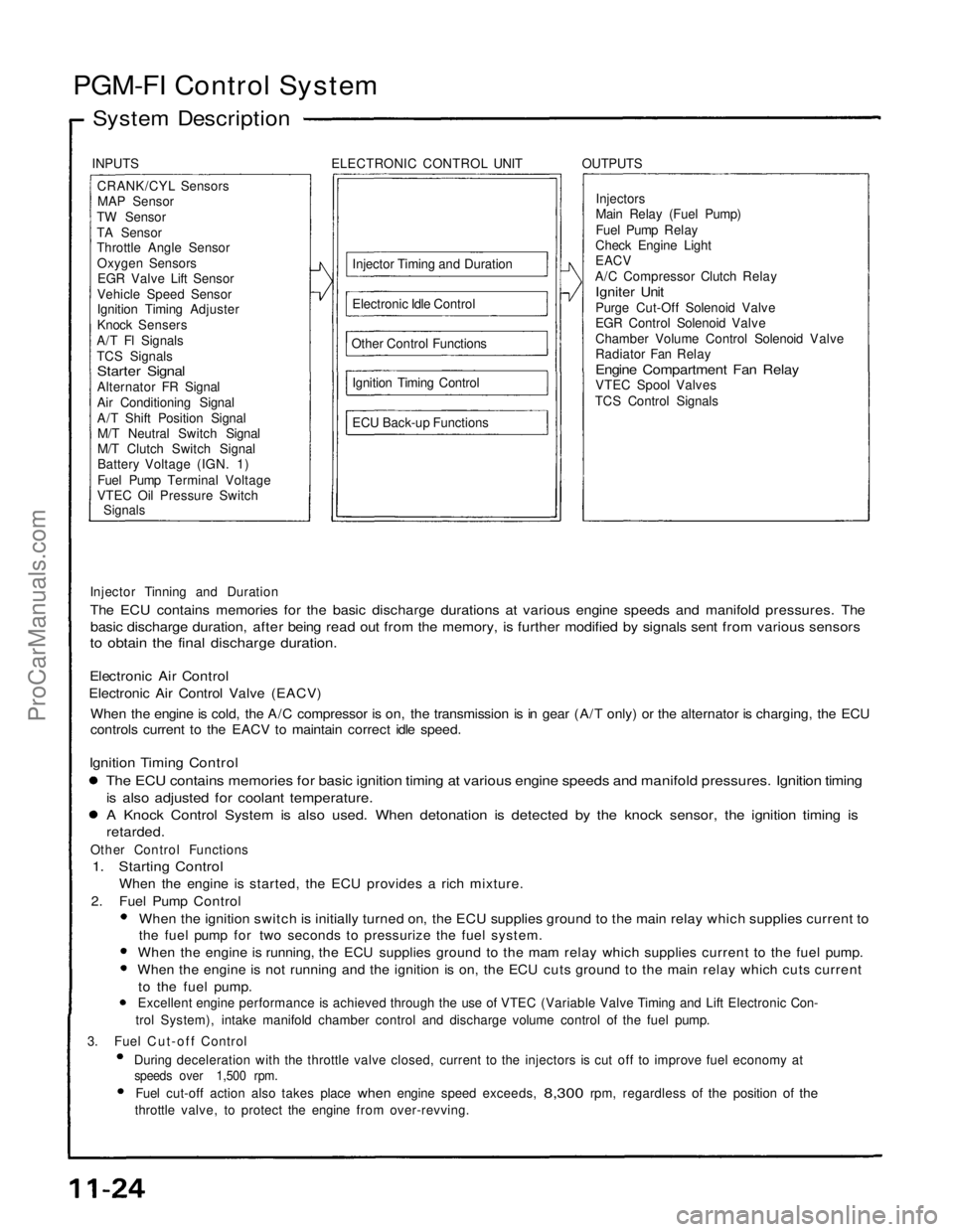
PGM-FI Control System
System Description
INPUTS ELECTRONIC CONTROL UNIT OUTPUTSCRANK/CYL SensorsMAP Sensor
TW Sensor
TA Sensor
Throttle Angle Sensor Oxygen SensorsEGR Valve Lift Sensor
Vehicle Speed Sensor
Ignition Timing Adjuster
Knock Sensers
A/T Fl Signals
TCS Signals
Starter Signal
Alternator FR Signal
Air Conditioning Signal
A/T Shift Position Signal M/T Neutral Switch Signal
M/T Clutch Switch Signal
Battery Voltage (IGN. 1)
Fuel Pump Terminal Voltage
VTEC Oil Pressure Switch
Signals
Injector Timing and Duration
Electronic Idle Control
Other Control Functions Ignition Timing Control
ECU Back-up Functions Injectors
Main Relay (Fuel Pump)
Fuel Pump Relay
Check Engine Light
EACV
A/C Compressor Clutch Relay
Igniter Unit
Purge Cut-Off Solenoid Valve
EGR Control Solenoid Valve
Chamber Volume Control Solenoid Valve
Radiator Fan Relay
Engine Compartment Fan Relay
VTEC Spool Valves
TCS Control Signals
Injector Tinning and Duration
The ECU contains memories for the basic discharge durations at various engine speeds and manifold pressures. The
basic discharge duration, after being read out from the memory, is further modified by signals sent from various sensors
to obtain the final discharge duration.
Electronic Air Control
Electronic Air Control Valve (EACV)
When the engine is cold, the A/C compressor is on, the transmission is in gear (A/T only) or the alternator is charging, the ECU
controls current to the EACV to maintain correct idle speed.
Ignition Timing Control
The ECU contains memories for basic ignition timing at various engine speeds and manifold pressures. Ignition timing
is also adjusted for coolant temperature.
A Knock Control System is also used. When detonation is detected by the knock sensor, the ignition timing is
retarded.
Other Control Functions
1. Starting Control
When the engine is started, the ECU provides a rich mixture.
2. Fuel Pump Control
When the ignition switch is initially turned on, the ECU supplies ground to the main relay which supplies current to
the fuel pump for two seconds to pressurize the fuel system.
When the engine is running, the ECU supplies ground to the mam relay which supplies current to the fuel pump.
When the engine is not running and the ignition is on, the ECU cuts ground to the main relay which cuts current
to the fuel pump.
Excellent engine performance is achieved through the use of VTEC (Variable Valve Timing and Lift Electronic Con-
trol System), intake manifold chamber control and discharge volume control of the fuel pump.
3. Fuel Cut-off Control During deceleration with the throttle valve closed, current to the injectors is cut off to improve fuel economy at
speeds over 1,500 rpm.
Fuel cut-off action also takes place
when
engine speed exceeds,
8,300
rpm, regardless
of the
position
of the
throttle valve, to protect the engine from over-revving.ProCarManuals.com
Page 1481 of 1640
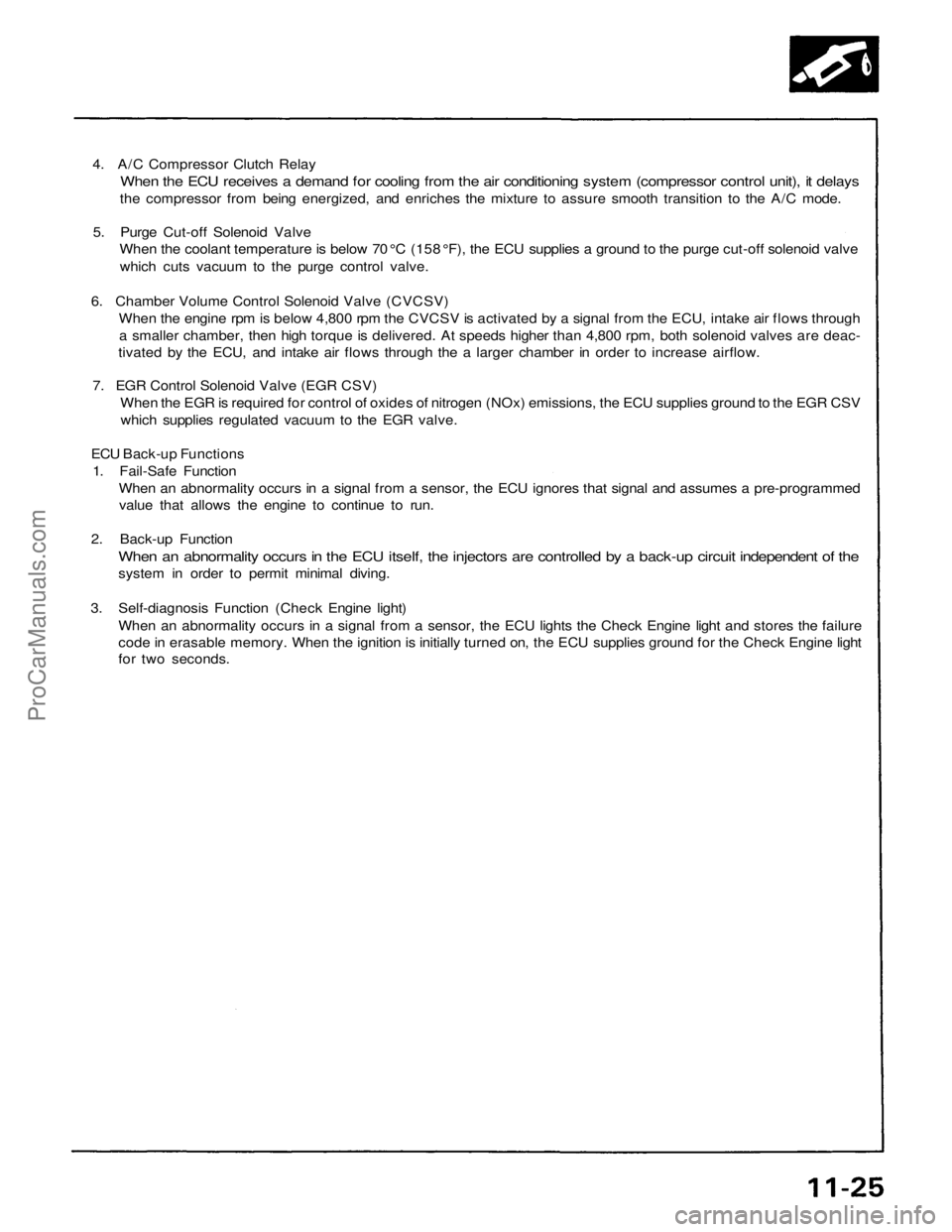
4. A/C Compressor Clutch Relay
When the ECU receives a demand for cooling from the air conditioning system (compressor control unit), it delays
the compressor from being energized, and enriches the mixture to assure smooth transition to the A/C mode.
5. Purge Cut-off Solenoid Valve
When the coolant temperature is below 70 °C (158 °F), the ECU supplies a ground to the purge cut-off solenoid valve
which cuts vacuum to the purge control valve.
6. Chamber Volume Control Solenoid Valve (CVCSV)
When the engine rpm is below 4,800 rpm the CVCSV is activated by a signal from the ECU, intake air flows through
a smaller chamber, then high torque is delivered. At speeds higher than 4,800 rpm, both solenoid valves are deac-
tivated by the ECU, and intake air flows through the a larger chamber in order to increase airflow.
7. EGR Control Solenoid Valve (EGR CSV)
When the EGR is required for control of oxides of nitrogen (NOx) emissions, the ECU supplies ground to the EGR CSV
which supplies regulated vacuum to the EGR valve.
ECU Back-up Functions
1. Fail-Safe Function
When an abnormality occurs in a signal from a sensor, the ECU ignores that signal and assumes a pre-programmed
value that allows the engine to continue to run.
2. Back-up Function
When an abnormality occurs in the ECU itself, the injectors are controlled by a back-up circuit independent of the
system in order to permit minimal diving.
3. Self-diagnosis Function (Check Engine light)
When an abnormality occurs in a signal from a sensor, the ECU lights the Check Engine light and stores the failure
code in erasable memory. When the ignition is initially turned on, the ECU supplies ground for the Check Engine light
for two seconds.ProCarManuals.com
Page 1485 of 1640
Idle Control System
System Description (cont'd)
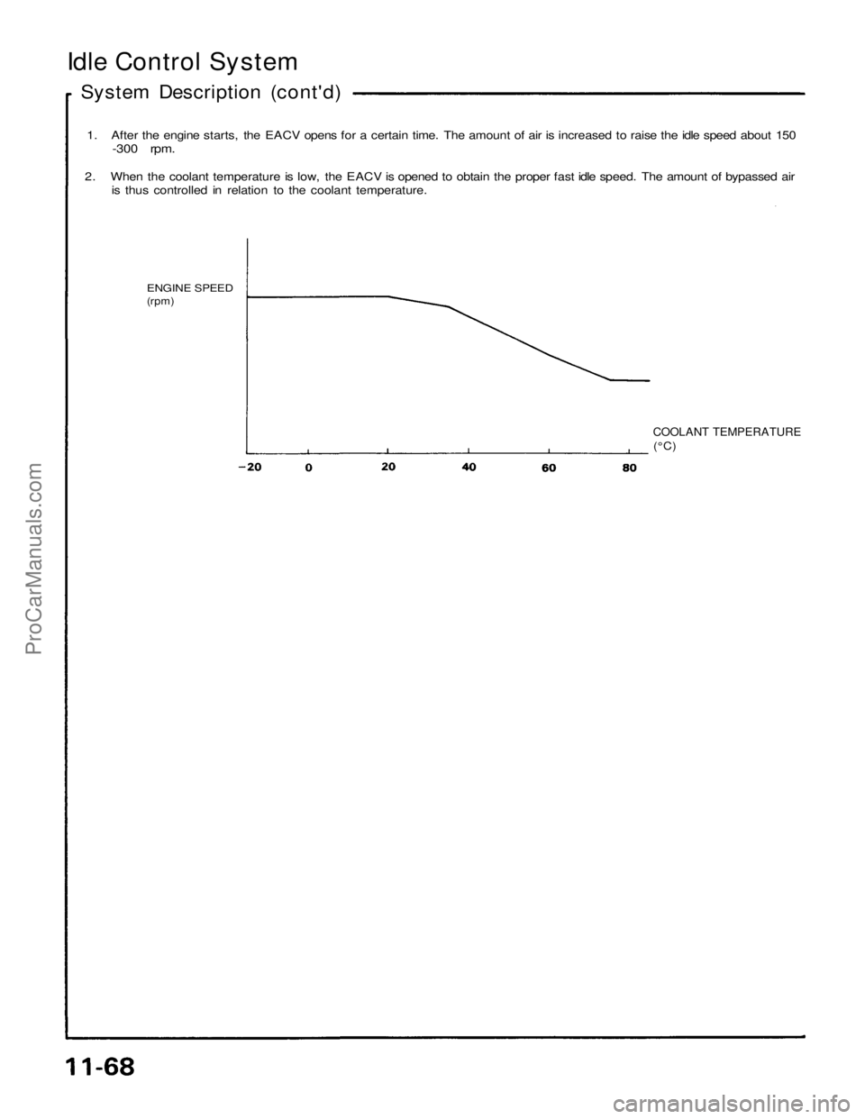
1. After the engine starts, the EACV opens for a certain time. The amount of air is increased to raise the idle speed about 150
-300 rpm.
2. When the coolant temperature is low, the EACV is opened to obtain the proper fast idle speed. The amount of bypassed air
is thus controlled in relation to the coolant temperature.
ENGINE SPEED
(rpm)
COOLANT TEMPERATURE
(°C)ProCarManuals.com
Page 1497 of 1640
Fast Idle Valve
Description
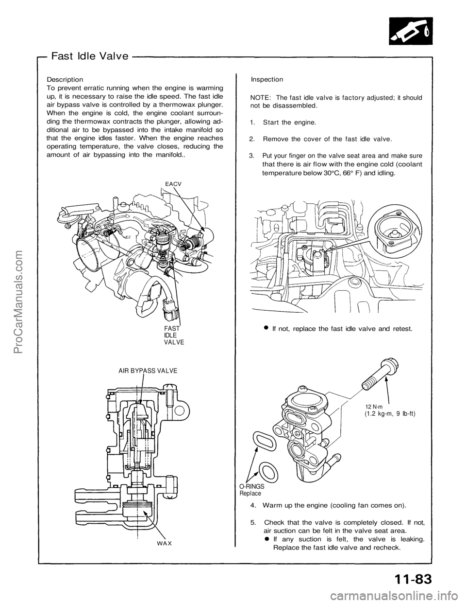
To prevent erratic running when the engine is warming up, it is necessary to raise the idle speed. The fast idle
air bypass valve is controlled by a thermowax plunger.
When the engine is cold, the engine coolant surroun- ding the thermowax contracts the plunger, allowing ad-
ditional air to be bypassed into the intake manifold so
that the engine idles faster. When the engine reaches operating temperature, the valve closes, reducing the
amount of air bypassing into the manifold..
Inspection
NOTE: The fast idle valve is factory adjusted; it should
not be disassembled.
1. Start the engine.
2. Remove the cover of the fast idle valve.
3. Put your finger on the valve seat area and make sure
that there is air flow with the engine cold (coolant
temperature below 30°C, 66° F) and idling.
EACV
If not, replace the fast idle valve and retest.
FAST
IDLE
VALVE
AIR BYPASS VALVE
12 N·m
(1.2 kg-m, 9 Ib-ft)
O-RINGS
Replace
4. Warm up the engine (cooling fan comes on).
5. Check that the valve is completely closed. If not, air suction can be felt in the valve seat area. If any suction is felt, the valve is leaking.
Replace the fast idle valve and recheck.
WAXProCarManuals.com
Page 1520 of 1640
Air Intake System
Throttle Body
Description
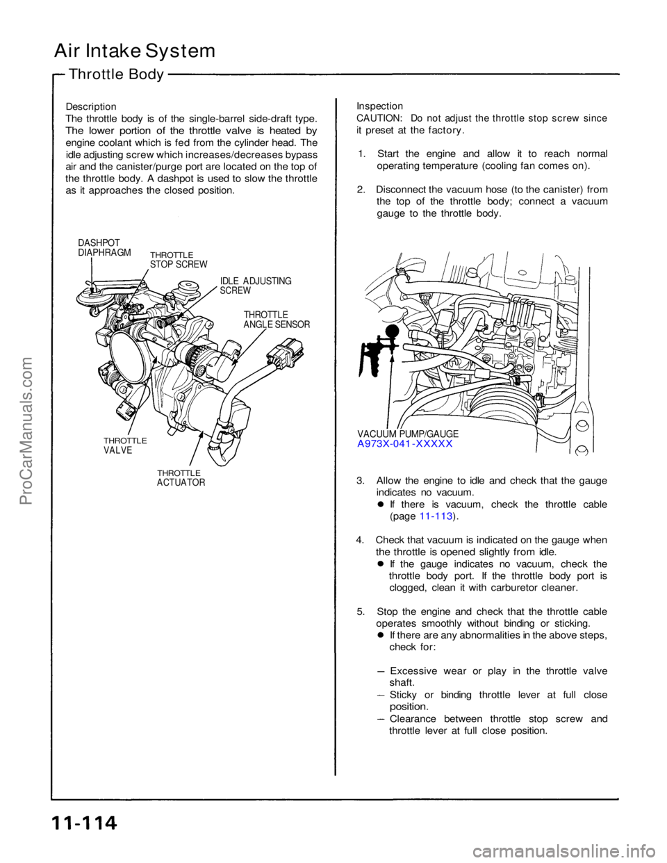
The throttle body is of the single-barrel side-draft type.
The lower portion of the throttle valve is heated by
engine coolant which is fed from the cylinder head. Theidle adjusting screw which increases/decreases bypass
air and the canister/purge port are located on the top of
the throttle body. A dashpot is used to slow the throttle as it approaches the closed position.
Inspection
CAUTION: Do not adjust the throttle stop screw since
it preset at the factory.
1. Start the engine and allow it to reach normal operating temperature (cooling fan comes on).
2. Disconnect the vacuum hose (to the canister) from the top of the throttle body; connect a vacuum
gauge to the throttle body.
DASHPOT
DIAPHRAGM
THROTTLE
STOP SCREW
IDLE ADJUSTING
SCREW
THROTTLE
ANGLE SENSOR
VACUUM PUMP/GAUGE
A973X-041 -XXXXX
THROTTLE
VALVE
THROTTLE
ACTUATOR
3. Allow the engine to idle and check that the gauge
indicates no vacuum. If there is vacuum, check the throttle cable
(page 11-113).
4. Check that vacuum is indicated on the gauge when
the throttle is opened slightly from idle.
If the gauge indicates no vacuum, check the
throttle body port. If the throttle body port is clogged, clean it with carburetor cleaner.
5. Stop the engine and check that the throttle cable operates smoothly without binding or sticking. If there are any abnormalities in the above steps,
check for:
Excessive wear or play in the throttle valve
shaft.
Sticky or binding throttle lever at full close
position.
Clearance between throttle stop screw and
throttle lever at full close position.ProCarManuals.com