1991 ACURA NSX coolant temperature
[x] Cancel search: coolant temperaturePage 1015 of 1640
14. Relieve fuel pressure (see section 11).
Do not smoke while working on fuel
system; keep open flame or spark away from work
area. Drain fuel only into an approved container.
1 5. Disconnect the fuel feed pipe and the return hose
(page 5-21).
16. Remove the ignition coil covers, the wire harness covers, the ignition coils and the connectors (page
6-23).
17. Remove the water hoses, then remove the expan- sion tank (page 5-21).
18. Remove the breather hose, and the air cleaner housing (page 5-22).
19. Remove the brake booster hose, the evaporative emission (EVAP) control canister hose and other
hoses from the intake manifold and throttle body
(page 5-22).
20. Remove the emission control box (page 5-23). Do not disconnect emission hose.Disconnect the three connectors before
removing.
21. Remove the connector, the terminal and the alternator.
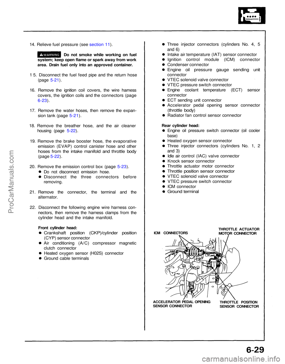
22. Disconnect the following engine wire harness con- nectors, then remove the harness clamps from thecylinder head and the intake manifold.
Front cylinder head:
Crankshaft position (CKP)/cylinder position
(CYP) sensor connector
Air conditioning (A/C) compressor magnetic clutch connector
Heated oxygen sensor (H02S) connector
Ground cable terminals Three injector connectors (cylinders No. 4, 5
and 6)
Intake air temperature (IAT) sensor connector
Ignition control module (ICM) connector
Condenser connector
Engine oil pressure gauge sending unit
connector
VTEC solenoid valve connector
VTEC pressure switch connector
Engine coolant temperature (ECT) sensor
connector
ECT sending unit connector
Accelerator pedal opening sensor connector
(throttle body)
Radiator fan control sensor connector
Rear cylinder head: Engine oil pressure switch connector (oil cooler
base)
Heated oxygen sensor connector
Three injector connectors (cylinders No. 1, 2
and 3)
Idle air control (IAC) valve connector
Knock sensor connector
Throttle actuator motor connector
Throttle position sensor connector
VTEC solenoid valve connectorVTEC pressure switch connector
ICM connector
Ground terminal
ICM CONNECTORS THROTTLE ACTUATOR
MOTOR CONNECTOR
THROTTLE POSITION
SENSOR CONNECTOR
ACCELERATOR PEDAL OPENING
SENSOR CONNECTORProCarManuals.com
Page 1049 of 1640
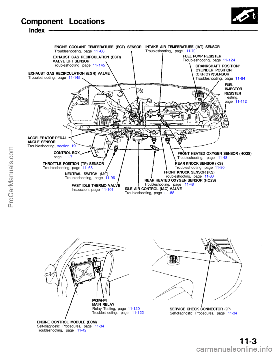
Component Locations
Index
ENGINE COOLANT TEMPERATURE (ECT) SENSOR
Troubleshooting, page 11 -66
INTAKE AIR TEMPERATURE (IAT) SENSOR
Troubleshooting, page 11-70
FUEL PUMP RESISTER
Troubleshooting, page 11-124
CRANKSHAFT POSITION/CYLINDER POSITION
(CKP/CYP) SENSOR
Troubleshooting, page 11-64
FUEL
INJECTOR
RESISTER
Testing,
page 11-112
FRONT HEATED OXYGEN SENSOR (HO2S)
Troubleshooting, page 11-48
REAR KNOCK SENSOR (KS)
Troubleshooting, page 11-80
FRONT KNOCK SENSOR (KS)
Troubleshooting, page 11-80
REAR HEATED OXYGEN SENSOR (HO2S)
Troubleshooting, page 11-48
IDLE AIR CONTROL (IAC) VALVE
Troubleshooting, page 11 -88
FAST IDLE THERMO VALVE
Inspection, page 11-101
NEUTRAL SWITCH (M/T)
Troubleshooting, page 11-96
SERVICE CHECK CONNECTOR (2P)
Self-diagnostic Procedures, page 11-34
ENGINE CONTROL MODULE (ECM)
Self-diagnostic Procedures, page 11-34
Troubleshooting, page 11-42
PGM-FI
MAIN RELAY
Relay Testing, page 11-120
Troubleshooting, page 11-122
THROTTLE POSITION (TP) SENSOR
Troubleshooting, page 11 -68
CONTROL BOX
page, 11-7
ACCELERATOR PEDAL
ANGLE SENSOR
Troubleshooting, section 19
EXHAUST GAS RECIRCULATION (EGR) VALVE
Troubleshooting, page 11-145
EXHAUST GAS RECIRCULATION (EGR)
VALVE LIFT SENSOR
Troubleshooting, page 11-145ProCarManuals.com
Page 1084 of 1640
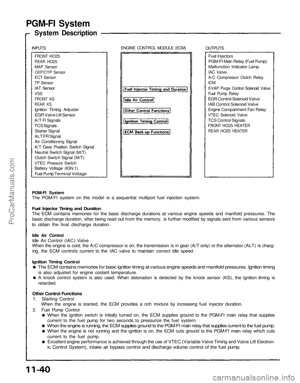
PGM-FI System
System Description
INPUTS
ENGINE CONTROL MODULE (ECM)
OUTPUTS
FRONT HO2S
REAR HO2S
MAP Sensor
CKP/CYP Sensor
ECT Sensor
TP Sensor
IAT Sensor
VSS
FRONT KS
REAR KS
Ignition Timing Adjuster
EGR Valve Lift Sensor
A/T Fl Signals
TCS Signals
Starter Signal
ALT FR Signal
Air Conditioning Signal
A/T Gear Position Switch Signal
Neutral Switch Signal (M/T)
Clutch Switch Signal (M/T)
VTEC Pressure Switch
Battery Voltage (IGN.1)
Fuel Pump Terminal Voltage
Fuel Injectors
PGM-FI Main Relay (Fuel Pump)
Malfunction Indicator Lamp
IAC Valve
A/C Compressor Clutch Relay
ICM
EVAP Purge Control Solenoid Valve
Fuel Pump Relay
EGR Control Solenoid Valve
IAB Control Solenoid Valve
Engine Compartment Fan Relay
VTEC Solenoid Valve
TCS Control Signals
FRONT HO2S HEATER
REAR HO2S HEATER
PGM-FI System
The PGM-FI system on this model is a sequential multiport fuel injection system.
Fuel Injector Timing and Duration
The ECM contains memories for the basic discharge durations at various engine speeds and manifold pressures. The
basic discharge duration, after being read out from the memory, is further modified by signals sent from various sensors
to obtain the final discharge duration.
Idle Air Control
Idle Air Control (IAC) Valve
When the engine is cold, the A/C compressor is on, the transmission is in gear (A/T only) or the alternator (ALT) is charg-
ing, the ECM controls current to the IAC valve to maintain correct idle speed.
Ignition Timing Control
The ECM contains memories for basic ignition timing at various engine speeds and manifold pressures. Ignition timing
is also adjusted for engine coolant temperature.
A knock control system is also used. When detonation is detected by the knock sensor (KS), the ignition timing is
retarded.
Other Control Functions
1. Starting Control
When the engine is started, the ECM provides a rich mixture by increasing fuel injector duration.
2. Fuel Pump Control
When the ignition switch is initially turned on, the ECM supplies ground to the PGM-FI main relay that supplies
current to the fuel pump for two seconds to pressurize the fuel system.
When the engine is running, the ECM supplies ground to the PGM-FI main relay that supplies current to the fuel pump.
When the engine is not running and the ignition is on, the ECM cuts ground to the PGM-FI main relay which cuts
current to the fuel pump.
Excellent engine performance is achieved through the use of VTEC (Variable Valve Timing and Valve Lift Electron-
ic Control System), intake air bypass control and discharge volume control of the fuel pump.ProCarManuals.com
Page 1085 of 1640
3. Fuel Cut-off Control
During deceleration with the throttle valve closed, current to the fuel injectors is cut off to improve fuel economy
at speeds over 1,500 rpm.
Fuel cut-off action also takes place when engine speed exceeds, 8,300 rpm, regardless of the position of the
throttle valve, to protect the engine from over-revving.
4. A/C Compressor Clutch Relay
When the ECM receives a demand for cooling from the air conditioning system, it delays the compressor from being
energized, and enriches the mixture to assure smooth translation to the A/C mode.
5. Evaporative Emission (EVAP) Purge Control Solenoid Valve
When the engine coolant temperature is below 1 58 °F (70°C) the ECM supplies a ground to the EVAP purge control
solenoid valve which cuts vacuum to the EVAP purge control diaphragm valve.
6. Intake Air Bypass (IAB) Control Solenoid Valve
When the engine speed is below 4,800 rpm, the IAB control solenoid valve is activated by a signal from the ECM.
Intake air then flows through the smaller chamber, and hight torque is delivered. To increase air flow at engine speeds
higher than 4,800 rpm, the solenoid valve is deactivated by the ECM, and the intake air flows through the larger
chamber.
7. Exhaust Gas Recirculation (EGR) Control Solenoid Valve
When the EGR is required for control of oxides of nitrogen (NOx) emissions, the ECM supplies ground to the EGR
control solenoid valve which supplies regulated vacuum to the EGR valve.
ECM fail-safe/back-up Functions
1. Fail-Safe Function
When an abnormality occurs in a signal from a sensor, the ECM ignores that signal and assumes a pre-programmed
valve for that sensor that allows the engine to continue to run.
2. Back-up Function
When an abnormality occurs in the ECM itself, the fuel injectors are controlled by a back-up circuit independent of
the system in order to permit minimal driving.
3. Self-diagnosis Function [Malfunction Indicator Lamp (MIL)]
When an abnormality occurs in a signal from a sensor, the ECM lights the MIL and stores the diagnostic trouble code
in erasable memory. When the ignition is initially turned in, the ECM supplies ground for the MIL for two seconds
to check the MIL bulb condition.ProCarManuals.com
Page 1105 of 1640
Fast Idle Thermo Valve
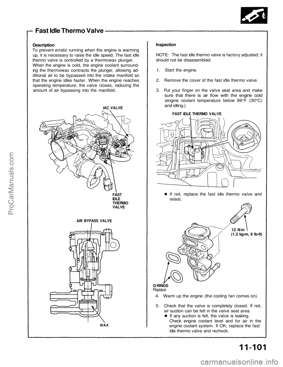
Description
To prevent erratic running when the engine is warming
up, it is necessary to raise the idle speed. The fast idle
thermo valve is controlled by a thermowax plunger.
When the engine is cold, the engine coolant surround-ing the thermowax contracts the plunger, allowing ad-
ditional air to be bypassed into the intake manifold so
that the engine idles faster. When the engine reaches operating temperature, the valve closes, reducing theamount of air bypassing into the manifold.
IAC VALVE
FAST
IDLE
THERMO
VALVE
AIR BYPASS VALVE
WAX
Inspection
NOTE: The fast idle thermo valve is factory adjusted; it
should not be disassembled. 1. Start the engine.
2. Remove the cover of the fast idle thermo valve.
3. Put your finger on the valve seat area and make
sure that there is air flow with the engine cold
(engine coolant temperature below 86°F (30°C)
and idling.)
FAST IDLE THERMO VALVE
If not, replace the fast idle thermo valve and
retest.
12 N.
m
(1.2 kg-m, 9 Ib-ft)
O-RINGS
Replace
4. Warm up the engine (the cooling fan comes on).
5. Check that the valve is completely closed. If not, air suction can be felt in the valve seat area.If any suction is felt, the valve is leaking.
Check engine coolant level and for air in the
engine coolant system. If OK, replace the fast idle thermo valve and recheck.ProCarManuals.com
Page 1142 of 1640
Emission Control System
Description
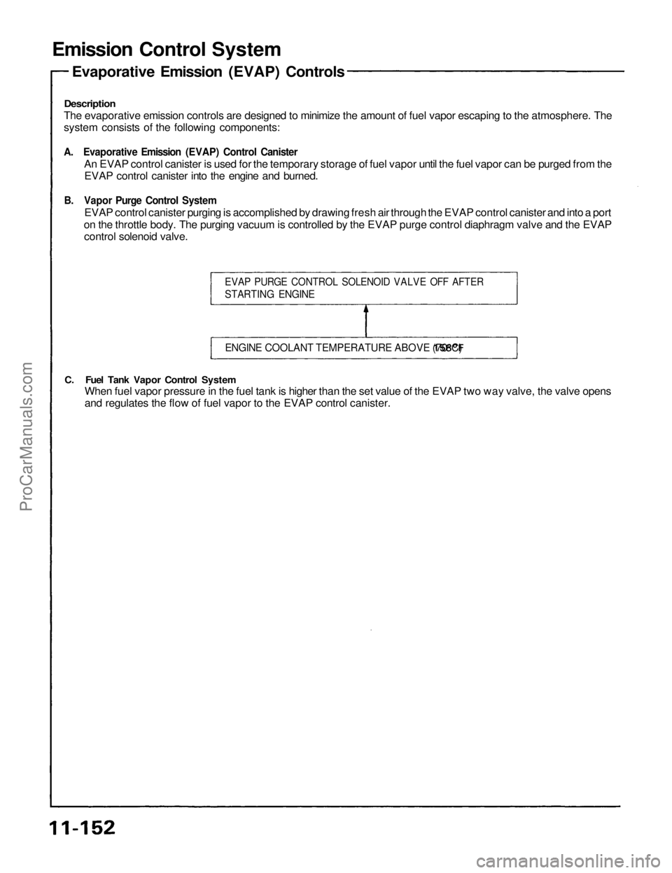
The evaporative emission controls are designed to minimize the amount of fuel vapor escaping to the atmosphere. The
system consists of the following components:
A. Evaporative Emission (EVAP) Control Canister
An EVAP control canister is used for the temporary storage of fuel vapor until the fuel vapor can be purged from the
EVAP control canister into the engine and burned.
B. Vapor Purge Control System
EVAP control canister purging is accomplished by drawing fresh air through the EVAP control canister and into a port
on the throttle body. The purging vacuum is controlled by the EVAP purge control diaphragm valve and the EVAP
control solenoid valve.
C. Fuel Tank Vapor Control System
When fuel vapor pressure in the fuel tank is higher than the set value of the EVAP two way valve, the valve opens
and regulates the flow of fuel vapor to the EVAP control canister.
EVAP PURGE CONTROL SOLENOID VALVE OFF AFTER
STARTING ENGINE
ENGINE COOLANT TEMPERATURE ABOVE
158°F
(70°C)
Evaporative Emission (EVAP) ControlsProCarManuals.com
Page 1178 of 1640
Description
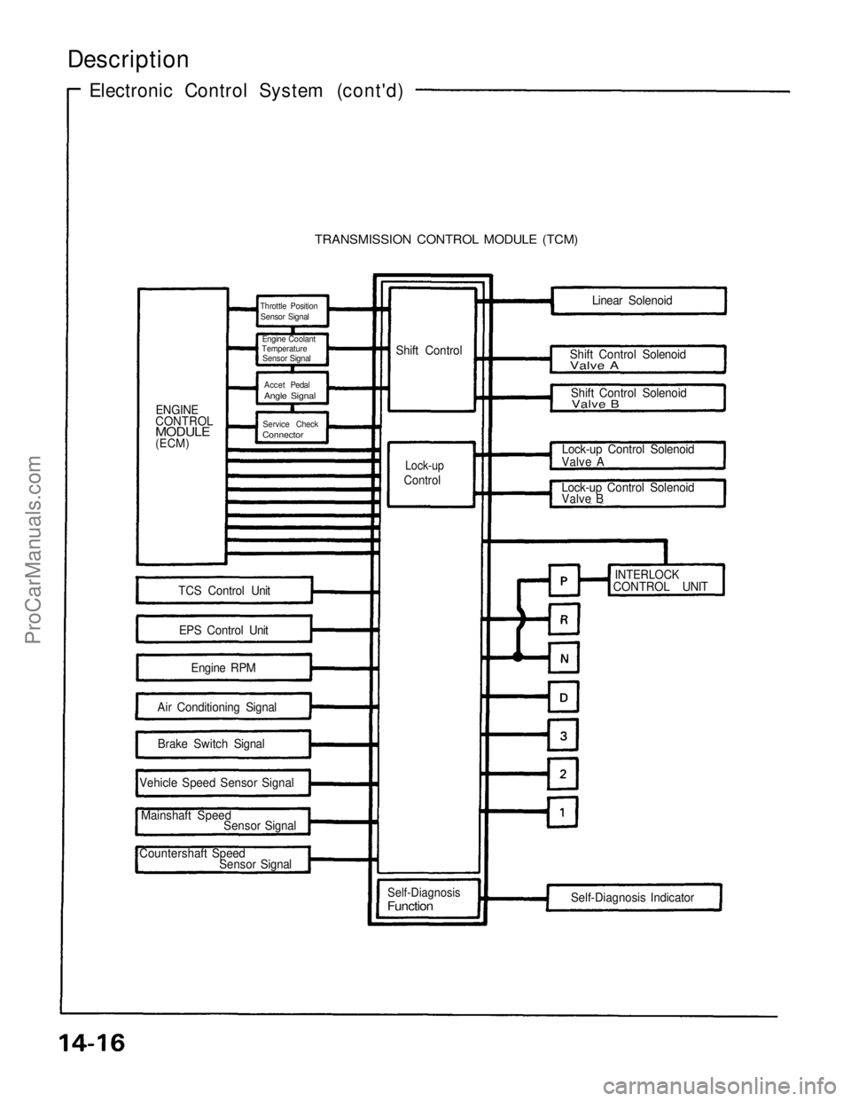
Electronic Control System (cont'd)
TRANSMISSION CONTROL MODULE (TCM)
ENGINE
CONTROL
MODULE
(ECM) Shift Control
Lock-up
Control
TCS Control Unit
EPS Control Unit Engine RPM
Air Conditioning Signal Brake Switch Signal
Vehicle Speed Sensor Signal
Mainshaft Speed Sensor Signal
Countershaft Speed Sensor Signal
Self-Diagnosis
Function
Self-Diagnosis Indicator
INTERLOCK
CONTROL UNIT
Lock-up Control Solenoid
Valve B
Lock-up Control Solenoid
Valve A Shift Control Solenoid
Valve B
Shift Control Solenoid
Valve A
Linear Solenoid
Throttle Position
Sensor Signal
Engine Coolant
Temperature
Sensor Signal
Accet Pedal
Angle Signal
Service Check
Connector
ProCarManuals.com
Page 1207 of 1640
Component Location
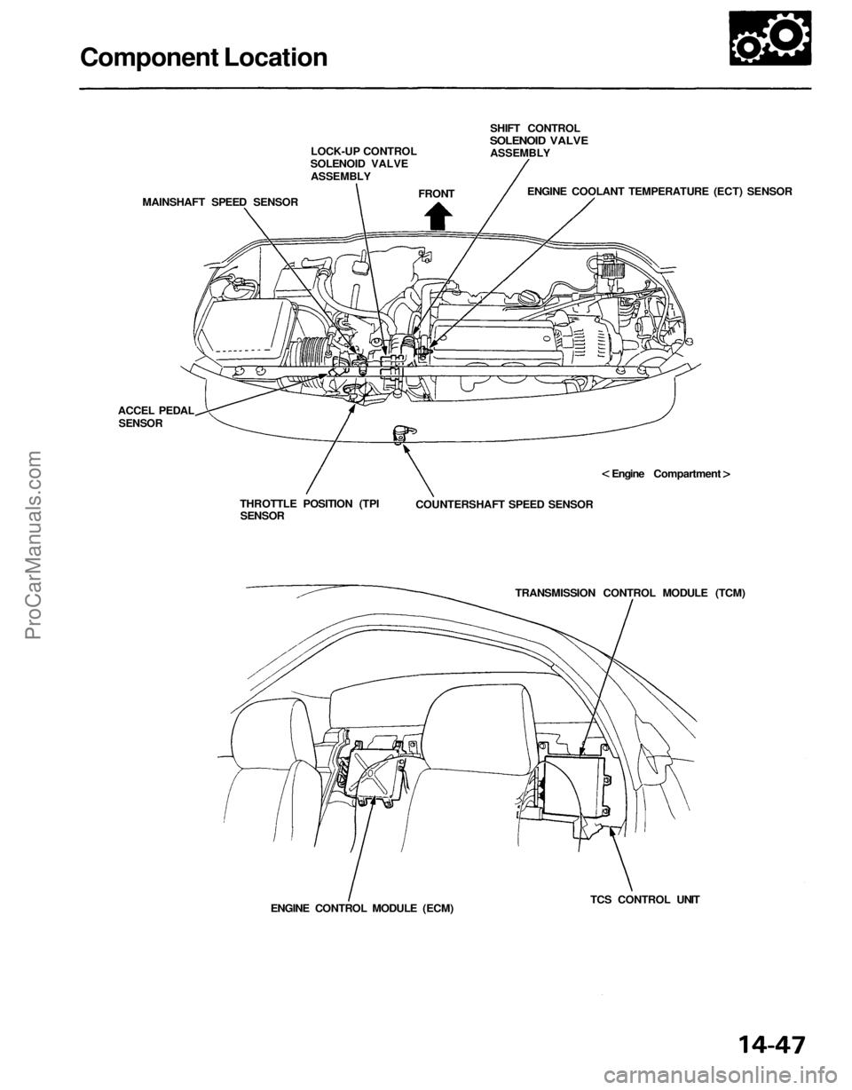
LOCK-UP CONTROL
SOLENOID VALVE
ASSEMBLY
MAINSHAFT SPEED SENSOR
FRONT
SHIFT CONTROL
SOLENOID VALVE
ASSEMBLY
ENGINE COOLANT TEMPERATURE (ECT) SENSOR
Engine Compartment
COUNTERSHAFT SPEED SENSOR
TRANSMISSION CONTROL MODULE (TCM)
TCS CONTROL UNIT
ENGINE CONTROL MODULE (ECM)
THROTTLE POSITION (TPI
SENSOR
ACCEL PEDAL
SENSORProCarManuals.com