Page 955 of 1640
Security Alar m Syste m
Indicato r Replacemen t
1. Remov e th e doo r pane l (se e sectio n 20 ).
2 . Remov e th e tw o screw s fro m th e indicator .
3 . Remov e th e indicato r fro m th e doo r panel .
5-P CONNECTO RINDICATO
R
DOOR PANE L
Trunk Ke y Cylinde r Switc h Tes t
1. Ope n th e trun k li d an d remov e th e trun k rea r panel .
2 . Disconnec t th e 2- P connecto r fro m th e trun k ke y
cylinde r switch .
3 . Chec k continuit y a t th e switc h connecto r terminals .
• Ther e shoul d b e continuit y betwee n th e terminal s
whe n th e trun k loc k i s turne d t o UNLOC K wit h
the key .
• Ther e shoul d b e n o continuit y whe n th e loc k i s
released .
TRUNK KE Y
CYLINDE R SWITC H
2-PCONNECTO RTRUN
K KE Y
CYLINDE R
ProCarManuals.com
Page 973 of 1640

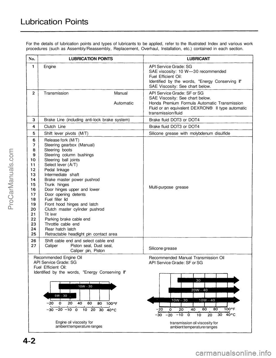
Lubrication Points
For the details of lubrication points and types of lubricants to be applied, refer to the Illustrated Index and various workprocedures (such as Assembly/Reassembly, Replacement, Overhaul, Installation, etc.) contained in each section.
No.
LUBRICATION POINTS
LUBRICANT
Engine
Transmission
Manual
Automatic
Brake Line (including anti-lock brake system)
Clutch Line Shift lever pivots (M/T)Release fork (M/T)Steering gearbox (Manual)
Steering boots Steering column bushings
Steering ball jointsSelect lever (A/T)
Pedal linkage Intermediate shaft
Brake master power pushrod
Trunk hinges Door hinges upper and lower
Door opening detents
Fuel filler lid
Front hood hinges and latch
Clutch master cylinder pushrod
Tilt lever
Parking brake cable end
Throttle cable end Rear hatch latchRetractable headlight pin contact area
Shift cable end and select cable end
Caliper Piston seal, Dust seal, Caliper pin, Piston
Recommended Engine Oil
API Service Grade: SG Fuel Efficient Oil:
Identified by the words, "Energy Conserving II" API Service Grade: SG
SAE viscosity: 10 W—30 recommended
Fuel Efficient Oil:
Identified by the words, "Energy Conserving II"
SAE Viscosity: See chart below.
API Service Grade: SF or SG SAE Viscosity: See chart below.
Honda Premium Formula Automatic Transmission
Fluid or an equivalent DEXRON® II type automatic
transmission fluid
Brake fluid DOT3 or DOT4
Brake fluid DOT3 or DOT4
Silicone grease with molybdenum disulfide
Multi-purpose grease
Silicone grease Recommended Manual Transmission Oil
API Service Grade: SF or SG
transmission oil viscosity forambient temperature ranges
Engine oil viscosity for
ambient temperature rangesProCarManuals.com
Page 990 of 1640

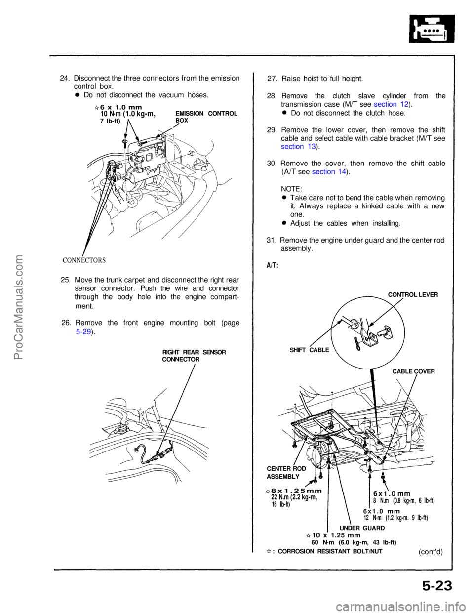
24. Disconnect the three connectors from the emission
control box.
6 x 1.0 mm
10 N .
m
(1.0 kg-m,
7 Ib-ft)
EMISSION CONTROL
BOX
CONNECTORS
25. Move the trunk carpet and disconnect the right rear sensor connector. Push the wire and connector
through the body hole into the engine compart-
ment.
26. Remove the front engine mounting bolt (page 5-29).
RIGHT REAR SENSOR
CONNECTOR 27. Raise hoist to full height.
28. Remove the clutch slave cylinder from the transmission case (M/T see section 12).
CONTROL LEVER
SHIFT CABLE CABLE COVER
CENTER ROD
ASSEMBLY
8x1.25
mm
22 N.m
(2.2 kg-m,
16 Ib-ft)
6x1.0
mm
8 N.m (0.8 kg-m, 6 Ib-ft)
6x1.0
mm
12 N
.
m (1.2 kg-m. 9 Ib-ft)
UNDER GUARD
10 x
1.25
mm
60 N
.
m (6.0 kg-m, 43 Ib-ft)
(cont'd)
: CORROSION RESISTANT BOLT/NUT
Do not disconnect the vacuum hoses.
Do not disconnect the clutch hose.
29. Remove the lower cover, then remove the shift cable and select cable with cable bracket (M/T see
section 13).
30. Remove the cover, then remove the shift cable (A/T see section 14).
NOTE:
Take care not to bend the cable when removingit. Always replace a kinked cable with a new
one.
Adjust the cables when installing.
31. Remove the engine under guard and the center rod
assembly.
A/T:ProCarManuals.com
Page 1377 of 1640
Climate control unit, stereo cassete/radio and glove box removal:
Disassemble in numbered sequence.
NOTE: Remove the center console panel.
CLIMATE CONTROL
UNIT
Disconnect the connectors.
SRS UNIT
STEREO
CASSETE RADIO
Disconnect the connectors.
GROUND CABLE
Passenger's:
GLOVE BOX
Disconnect the connectors.
PASSENGER'S
AIRBAG
DASHBOARD LOWER
COVER (Passenger's)
TRUNK LID OPENER
MAIN SWITCH
GLOVE BOX
LID
Installation is the reverse of the removal procedure.
NOTE: Make sure the connectors are connected properly.
(cont'd)ProCarManuals.com
Page 1404 of 1640
Blown No. 5 (10 A) fuse
(In the under-dash fuse box)
Blown No. 34 (15 A) fuse
(In the under-dash fuse box)
Safety indicator input
Safety indicator (Diodes)Brake light failure sensorDoor switch
Trunk latch switch
Retractable headlight control unit
(see page 23-174)
Poor ground
Open circuit, loose or disconnected
terminalsProCarManuals.com
Page 1580 of 1640

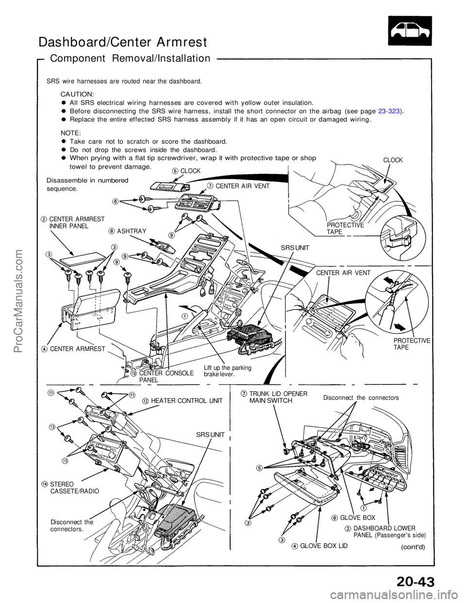
Dashboard/Center Armrest
Component Removal/Installation
SRS wire harnesses are routed near the dashboard.
CAUTION:
All SRS electrical wiring harnesses are covered with yellow outer insulation.Before disconnecting the SRS wire harness, install the short connector on the airbag (see page 23-323). Replace the entire effected SRS harness assembly if it has an open circuit or damaged wiring.
NOTE: Take care not to scratch or score the dashboard.Do not drop the screws inside the dashboard.
When prying with a flat tip screwdriver, wrap it with protective tape or shop
towel to prevent damage.
Disassemble in numbered
sequence.
CLOCK
CLOCK
CENTER AIR VENT
CENTER ARMREST
INNER PANEL
ASHTRAY
SRS UNIT
CENTER ARMREST CENTER CONSOLE
PANEL
Lift up the parking
brake lever.
HEATER CONTROL UNIT
SRS UNIT
STEREO
CASSETE/RADIO
Disconnect the
connectors.
GLOVE BOX LID
(cont'd)
DASHBOARD LOWER
PANEL (Passenger's side)
GLOVE BOX
Disconnect the connectors
TRUNK LID OPENER
MAIN SWITCH
PROTECTIVE
TAPE
CENTER AIR VENT
PROTECTIVE
TAPEProCarManuals.com