Page 805 of 1640

Safety Indicator
Component Location index
SRS components are located in this area. Review the SRS
component locations, precautions, and procedures in the
SRS section (24) before performing repairs or service.
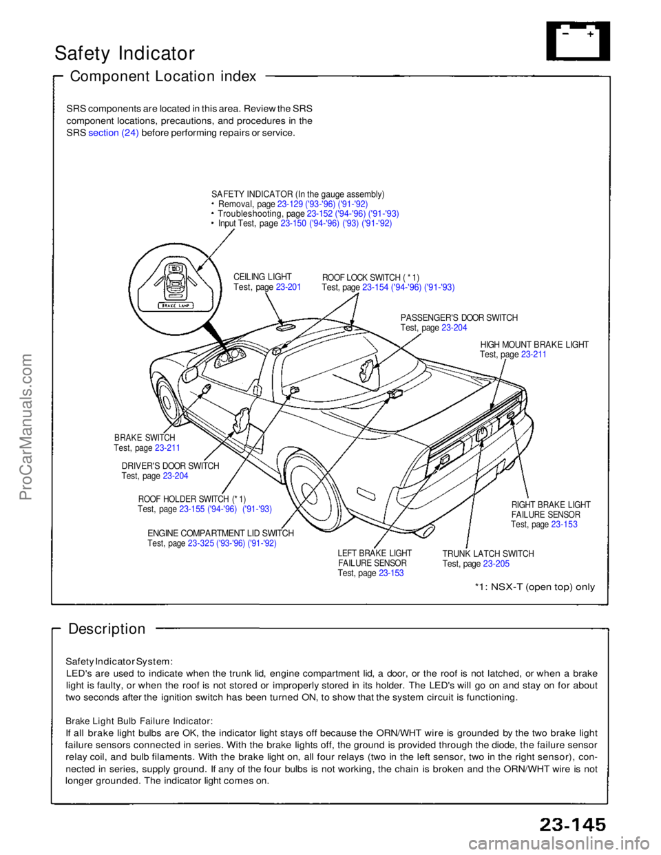
SAFET
Y
INDICATOR (In the gauge assembly)
Removal, page 23-129 ('93-'96) ('91-'92)
Troubleshooting, page 23-152 ('94-'96) ('91-'93)
Input Test, page 23-150 ('94-'96) ('93) ('91-'92)
CEILING LIGHT
Test, page 23-201
ROOF LOCK SWITCH ( * 1)
Test, page 23-154 ('94-'96) ('91-'93)
PASSENGER'S DOOR SWITCH
Test, page 23-204
HIGH MOUNT BRAKE LIGHT
Test, page 23-211
BRAKE SWITCH
Test, page 23-211
DRIVER'S DOOR SWITCH
Test, page 23-204
ROOF HOLDER SWITCH (* 1)
Test, page 23-155 ('94-'96) ('91-'93)
ENGINE COMPARTMENT LID SWITCH
Test, page 23-325 ('93-'96) ('91-'92)
LEFT BRAKE LIGHT
FAILURE SENSOR
Test, page 23-153
TRUNK LATCH SWITCH
Test, page 23-205
RIGHT BRAKE LIGHT
FAILURE SENSOR
Test, page 23-153
*1: NSX-T (open top) only
Description
Safety Indicator System: LED's are used to indicate when the trunk lid, engine compartment lid, a door, or the roof is not latched, or when a brake
light is faulty, or when the roof is not stored or improperly stored in its holder. The LED's will go on and stay on for about
two seconds after the ignition switch has been turned ON, to show that the system circuit is functioning.
Brake Light Bulb Failure Indicator:
If all brake light bulbs are OK, the indicator light stays off because the ORN/WHT wire is grounded by the two brake light
failure sensors connected in series. With the brake lights off, the ground is provided through the diode, the failure sensor relay coil, and bulb filaments. With the brake light on, all four relays (two in the left sensor, two in the right sensor), con-
nected in series, supply ground. If any of the four bulbs is not working, the chain is broken and the ORN/WHT wire is not
longer grounded. The indicator light comes on.ProCarManuals.com
Page 806 of 1640
Safety Indicator
Indicator Input Test
SRS components are located in this area. Review the SRS
component locations, precautions, and procedures in the
SRS section (24) before performing repairs or service.
Remove the dashboard lower cover, dashboard lower
pad and instrument panel. Disconnect the connector "A"
(30-P) from the gauge assembly (see page 23-127 ('93-'96)
('91-'92)).
Inspect the connector and socket terminals to be sure they
are all making good contact,
If the terminals are bent, loose, or corroded, repair
them as necessary, and recheck the system. If the terminals look OK, make the following input
tests at the connector.
– If a test indicates a problem, find and correct the
cause, then recheck the system.
– If all the input tests prove OK, the control unit must be faulty; replace it.
CONNECTOR "B"
CONNECTOR "
A"
YEL
GRN/BLK
BLU
RED/YEL
RED/YEL
BLK
ORN/WHT
BLK/WHT GRN/RED
GRN/BLU
View from wire sideProCarManuals.com
Page 834 of 1640
Lighting Syste m
Retracto r Switc h Remova l
SRS component s ar e locate d in thi s area . Revie w th e SR S
componen t locations , precautions , an d procedure s i n th e
SR S sectio n 24 befor e performin g repair s o r service .
1 . Remov e th e dashboar d lowe r cover , an d disconnec t
th e connectors .
2 . Remov e th e dashboar d lowe r pad .
DASHBOAR D LOWE R
COVE R
3. Remov e the tilt cover .
DASHBOAR D
LOWE R
PAD
TIL T COVE R
4. Remov e th e steerin g colum n covers .
UPPER COVE R
LOWE R COVE R
5. Disconnec t th e 5- P an d 10- P connector s fro m eac h
switch .
TCS SWITC H
5-P CONNECTO R
10- P CONNECTO R RETRACTO R SWITC H
6. Remov e th e si x screws, then remov e th e instrumen t
pane l tri m fro m th e dashboard .
INSTRUMEN T PANE L TRI M
RETRACTO R SWITC H
7. Remov e tw o screws , the n remov e th e retracto r
switc h fro m th e instrumen t pane l trim .
ProCarManuals.com
Page 862 of 1640
Side Marker/Turn Signal/Hazard Flasher System
Component Location Index
SRS components are located in this area. Review the SRS component locations, precautions, and procedures in the SRS
section (24) before performing repairs or service.
TURN SIGNAL INDICATOR LIGHTS(In the gauge assembly)
Gauge Assembly, page 23-125 HAZARD WARNING SWITCH
Removal, page 23-220
Test, page 23-221
HEADLIGHT SWITCH
Test, page 23-181
Replacement, page 23-182
TURN SIGNAL/HAZARD RELAY
Input Test, page 23-218
UNDER-DASH FUSE BOX TURN SIGNAL SWITCH
Test, page 23-181
Replacement, page 23-182 TURN SIGNAL CANCEL UNIT
Input Test, page 23-219
SIDE MARKER FLASHER CIRCUIT
(In the integrated control unit)
Input Test, page 23-168 ('94-'96) ('91-'93)ProCarManuals.com
Page 872 of 1640
Controller Remova l
SRS component s ar e locate d in thi s area . Revie w th e SR S
componen t locations , precautions , an d procedure s in th e
SR S sectio n 24 befor e performin g repair s o r service .
1 . Remov e th e dashboar d lowe r cover , an d disconnec t
th e connectors .
2 . Remov e th e dashboar d lowe r pad .
DASHBOAR D LOWE RCOVER
3. Remov e th e til t cover .
DASHBOAR D LOWE RPAD
TIL T COVE R
4. Remov e th e steerin g colum n covers .
UPPER COVE R
LOWE R COVE R
5. Disconnec t th e 5- P an d 10- P connector s fro m eac h
switch .
TCS SWITC H
5-P CONNECTO R
DAS H LIGHT S BRIGHTNES S
10- P CONNECTO R CONTROLLE R
6. Remov e th e si x screws , the n remov e th e instrumen t
pane l tri m fro m th e dashboard .
INSTRUMEN T PANE L TRI M
DAS H LIGHT S BRIGHTNES S
CONTROLLE R
7. Remov e tw o screws , the n remov e th e das h light s
brightnes s controlle r fro m th e instrumen t pane l trim .
ProCarManuals.com
Page 874 of 1640
Entry Light Timer System
Component Location Index
SRS components are located in this area. Review the SRS
component locations, precautions, and procedures in the
SRS section (24) before performing repairs or service.
Description: It the driver's door has been opened by the
outer handle, the foot well light and a light at the Ignition
switch go on and stay on for about eight seconds after
the driver's door has been dosed.
IGNITION KEY LIGHT
Replacement, page 23-229
FOOT WELL LIGHT
Replacement, page 23-229
DRIVER'S DOOR SWITCH
(Built into the door lock actuator assembly)
Test, page 23-204
UNDER-DASH FUSE BOX ENTRY LIGHT TIMER CIRCUIT
( Built into the integrated control unit)
Input Test, page 23-161 ('93-'96) ('91-'92)
ProCarManuals.com
Page 961 of 1640

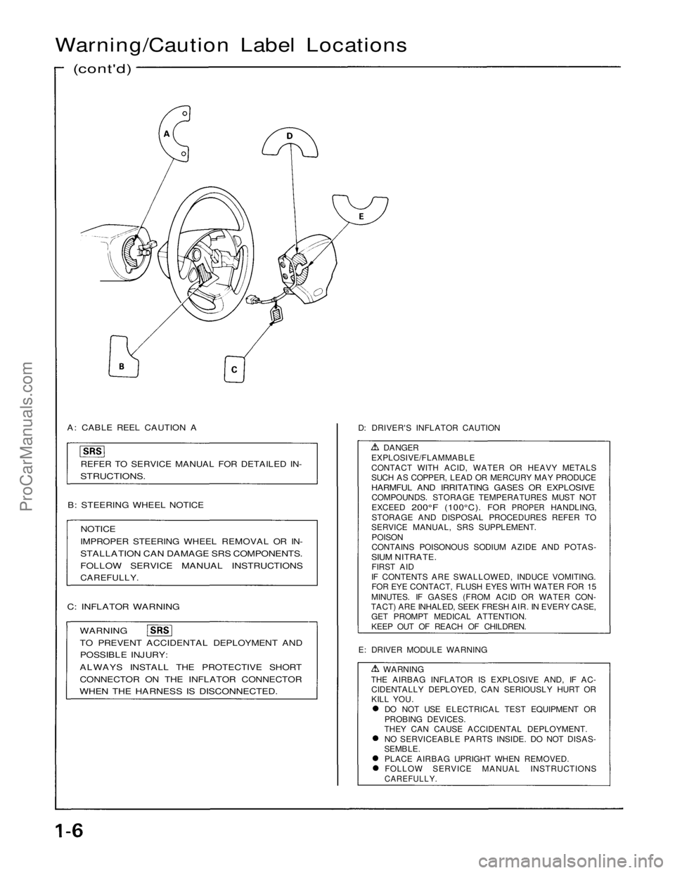
Warning/Caution Label Locations
(cont'd)
A: CABLE REEL CAUTION A
REFER TO SERVICE MANUAL FOR DETAILED IN-
STRUCTIONS.
B: STEERING WHEEL NOTICE
NOTICE
IMPROPER STEERING WHEEL REMOVAL OR IN-
STALLATION CAN DAMAGE SRS COMPONENTS.
FOLLOW SERVICE MANUAL INSTRUCTIONS
CAREFULLY.
C: INFLATOR WARNING
WARNING
TO PREVENT ACCIDENTAL DEPLOYMENT AND
POSSIBLE INJURY:
ALWAYS INSTALL THE PROTECTIVE SHORT
CONNECTOR ON THE INFLATOR CONNECTOR
WHEN THE HARNESS IS DISCONNECTED.
D: DRIVER'S INFLATOR CAUTION
DANGER
EXPLOSIVE/FLAMMABLE
CONTACT WITH ACID, WATER OR HEAVY METALS
SUCH AS COPPER, LEAD OR MERCURY MAY PRODUCE
HARMFUL AND IRRITATING GASES OR EXPLOSIVE
COMPOUNDS. STORAGE TEMPERATURES MUST NOT
EXCEED
200°F
(100°C).
FOR
PROPER
HANDLING,
STORAGE AND DISPOSAL PROCEDURES REFER TO
SERVICE MANUAL, SRS SUPPLEMENT.
POISON
CONTAINS POISONOUS SODIUM AZIDE AND POTAS-
SIUM NITRATE.
FIRST AID
IF CONTENTS ARE SWALLOWED, INDUCE VOMITING. FOR EYE CONTACT, FLUSH EYES WITH WATER FOR 15
MINUTES. IF GASES (FROM ACID OR WATER CON-
TACT) ARE INHALED, SEEK FRESH AIR. IN EVERY CASE, GET PROMPT MEDICAL ATTENTION.
KEEP OUT OF REACH OF CHILDREN.
E: DRIVER MODULE WARNING WARNING
THE AIRBAG INFLATOR IS EXPLOSIVE AND, IF AC- CIDENTALLY DEPLOYED, CAN SERIOUSLY HURT OR
KILL YOU.
DO NOT USE ELECTRICAL TEST EQUIPMENT OR
PROBING DEVICES.
THEY CAN CAUSE ACCIDENTAL DEPLOYMENT.
NO SERVICEABLE PARTS INSIDE. DO NOT DISAS-
SEMBLE.
PLACE AIRBAG UPRIGHT WHEN REMOVED.FOLLOW SERVICE MANUAL INSTRUCTIONS
CAREFULLY.ProCarManuals.com
Page 962 of 1640
(SUNVISOR)
F: DRIVER INFORMATION
ALWAYS WEAR YOUR SEAT BELT
THIS CAR IS EQUIPPED WITH A DRIVER AIR-
BAG AS A SUPPLEMENTAL RESTRAINT SYS-
TEM
(SRS)
IT IS DESIGNED TO SUPPLEMENT THE SEAT
BELT.
BEFORE DRIVING READ LABEL INSIDE THE
CONSOLE BOX.
G: MONITOR NOTICE
NOTICE
NO SERVICEABLE PARTS INSIDE.
REFER TO SERVICE MANUAL FOR DETAILED
INSTRUCTIONS.
H: STEERING COLUMN CAUTION
CAUTION
TO AVOID DAMAGING THE SRS CABLE OR REEL,
WHICH COULD MAKE THE SYSTEM INOPERA-
TIVE, REMOVE THE STEERING WHEEL BEFORE
REMOVING THE STEERING SHAFT CONNECTOR
BOLT.
L: CONSOLE BOX INFORMATION
AIRBAG INFORMATION
SUPPLEMENTAL RESTRAINT SYSTEM (SRS)
THE SRS MUST BE INSPECTED TEN YEARS AF-
TER IT IS INSTALLED. THE DATE OF INSTAL-
LATION IS SHOWN ON THE CERTIFICATION
PLATE, LOCATED ON THE DRIVER'S DOOR
JAMB.
DIAGNOSTIC CHECKS AND REPLACEMENT OF
SRS COMPONENTS MUST BE DONE BY AN
AUTHORIZED DEALER.
SEE YOUR OWNER'S MANUAL FOR ADDI-
TIONAL SRS INFORMATION.
(cont'd)ProCarManuals.com