Page 1044 of 1640
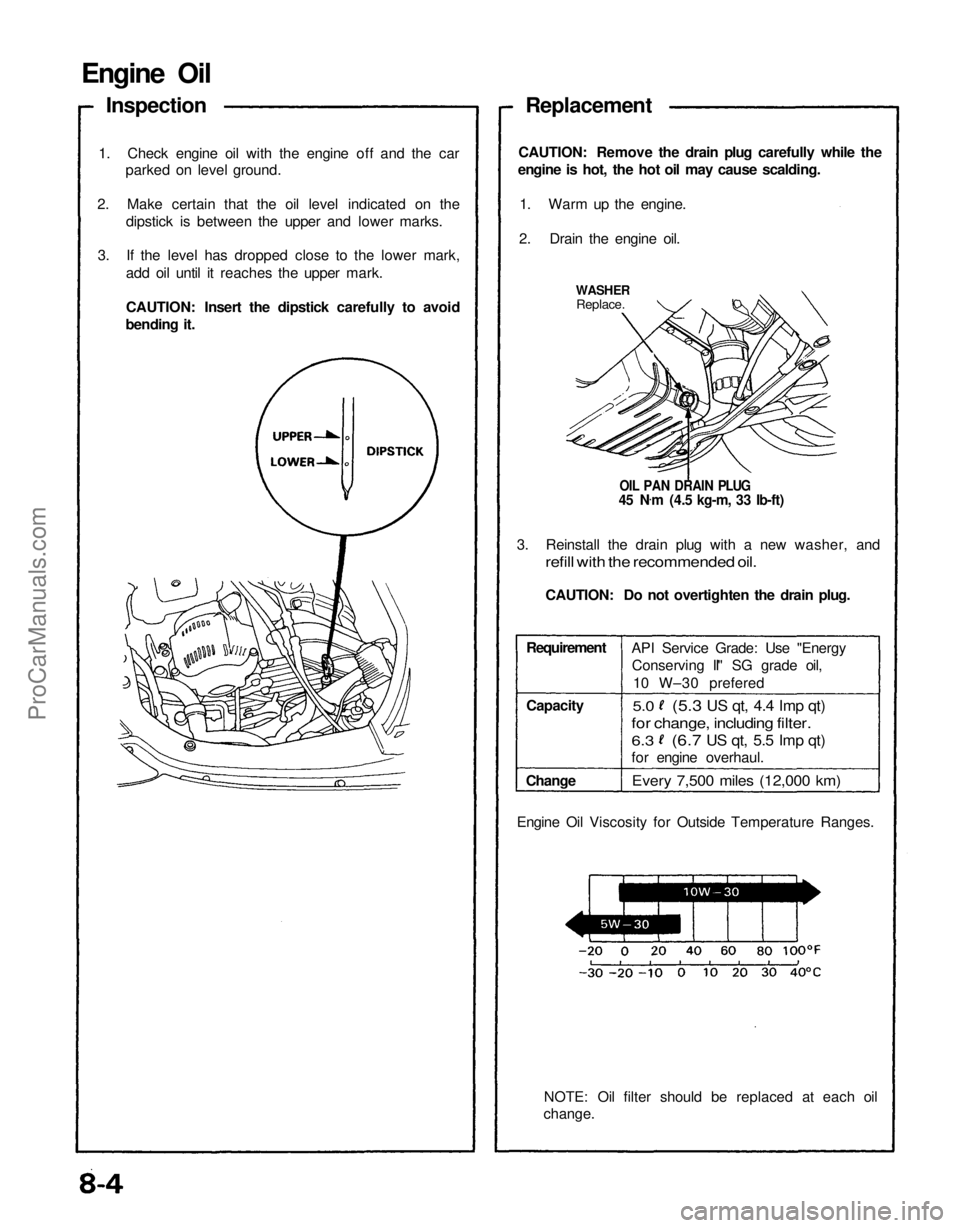
Engine Oil
Inspection
1. Check engine oil with the engine off and the car parked on level ground.
2. Make certain that the oil level indicated on the dipstick is between the upper and lower marks.
3. If the level has dropped close to the lower mark, add oil until it reaches the upper mark.
CAUTION: Insert the dipstick carefully to avoid
bending it. Replacement
CAUTION: Remove the drain plug carefully while the
engine is hot, the hot oil may cause scalding.
1. Warm up the engine.
2. Drain the engine oil.
WASHER
Replace.
OIL PAN DRAIN PLUG
45 N .
m (4.5 kg-m, 33 Ib-ft)
3. Reinstall the drain plug with a new washer, and
refill with the recommended oil.
CAUTION: Do not overtighten the drain plug.
Requirement
Capacity
Change API Service Grade: Use "Energy
Conserving II" SG grade oil,
10 W–30 prefered
5.0
Every 7,500 miles (12,000 km)
NOTE: Oil filter should be replaced at each oil
change.
Engine Oil Viscosity for Outside Temperature Ranges.
(5.3
US qt, 4.4 Imp qt)
for change, including filter.
6.3
(6.7
US qt, 5.5 Imp qt)
for engine overhaul.ProCarManuals.com
Page 1049 of 1640
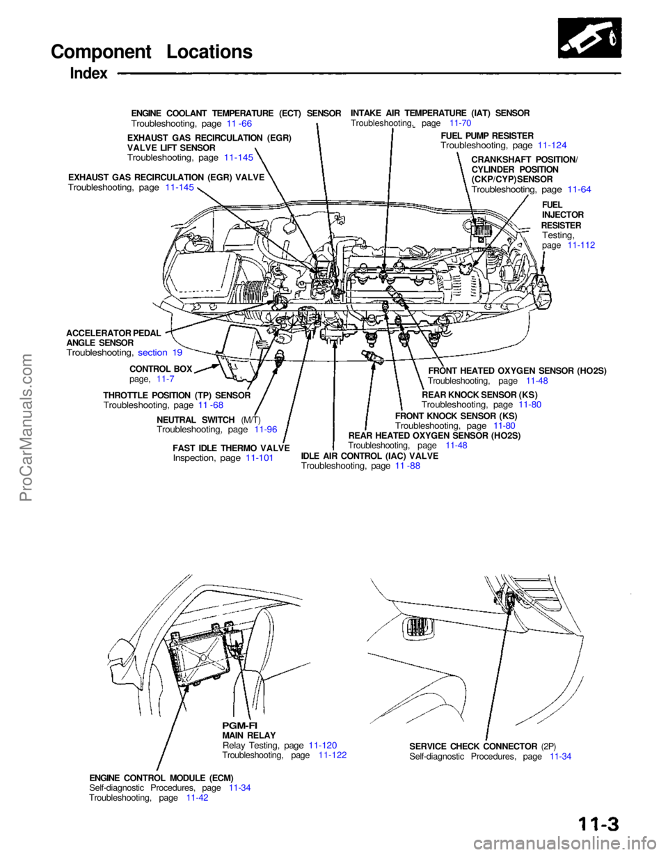
Component Locations
Index
ENGINE COOLANT TEMPERATURE (ECT) SENSOR
Troubleshooting, page 11 -66
INTAKE AIR TEMPERATURE (IAT) SENSOR
Troubleshooting, page 11-70
FUEL PUMP RESISTER
Troubleshooting, page 11-124
CRANKSHAFT POSITION/CYLINDER POSITION
(CKP/CYP) SENSOR
Troubleshooting, page 11-64
FUEL
INJECTOR
RESISTER
Testing,
page 11-112
FRONT HEATED OXYGEN SENSOR (HO2S)
Troubleshooting, page 11-48
REAR KNOCK SENSOR (KS)
Troubleshooting, page 11-80
FRONT KNOCK SENSOR (KS)
Troubleshooting, page 11-80
REAR HEATED OXYGEN SENSOR (HO2S)
Troubleshooting, page 11-48
IDLE AIR CONTROL (IAC) VALVE
Troubleshooting, page 11 -88
FAST IDLE THERMO VALVE
Inspection, page 11-101
NEUTRAL SWITCH (M/T)
Troubleshooting, page 11-96
SERVICE CHECK CONNECTOR (2P)
Self-diagnostic Procedures, page 11-34
ENGINE CONTROL MODULE (ECM)
Self-diagnostic Procedures, page 11-34
Troubleshooting, page 11-42
PGM-FI
MAIN RELAY
Relay Testing, page 11-120
Troubleshooting, page 11-122
THROTTLE POSITION (TP) SENSOR
Troubleshooting, page 11 -68
CONTROL BOX
page, 11-7
ACCELERATOR PEDAL
ANGLE SENSOR
Troubleshooting, section 19
EXHAUST GAS RECIRCULATION (EGR) VALVE
Troubleshooting, page 11-145
EXHAUST GAS RECIRCULATION (EGR)
VALVE LIFT SENSOR
Troubleshooting, page 11-145ProCarManuals.com
Page 1055 of 1640
System Description
Electrical Connections
FUSES
CLOCK (7.5 A)*
ACG
(120 A)**
ACG(S) (20 A)**
IG COIL (30 A)**
No. 2 (15 A)
No. 5 (10 A)
No.
4(15
A)
No. 7
(7.5
A)
In the under-hood
fuse/relay box In the engine
compartment
fuse/relay box
CKP/CYP
SENSOR
TO A/T
GEAR
POSITION
SWITCH
NEUTRAL
SWITCH
(M/T)
AUTO A/C
CONTROL
UNIT
CLUTCH
SWITCH
(M/T)
SERVICE
CHECK
CONNECTOR
A/C
PRESSURE
SWITCH A
A/C
PRESSURE
SWITCH B FUEL PUMP
RESISTORProCarManuals.com
Page 1076 of 1640
Troubleshooting
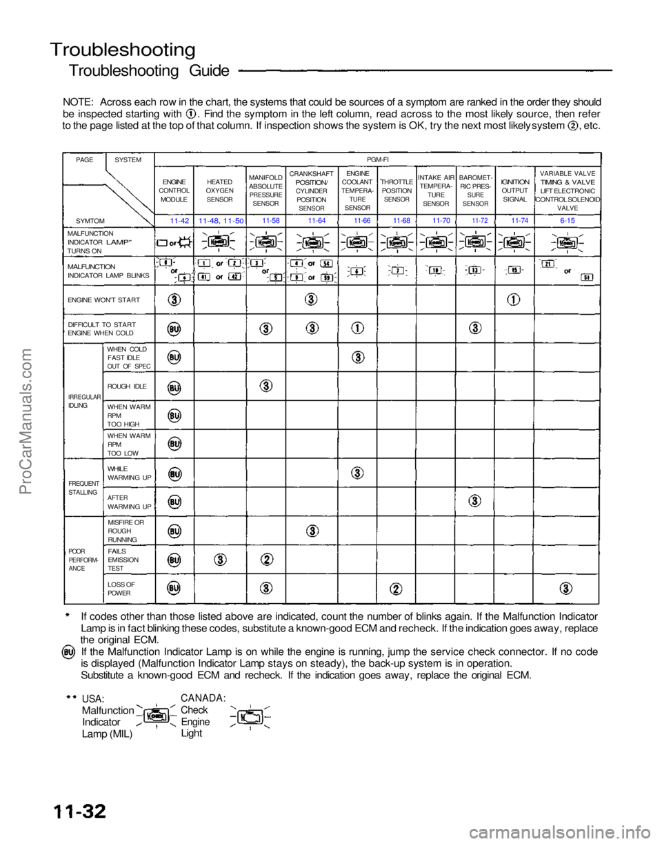
Troubleshooting Guide
NOTE: Across each row in the chart, the systems that could be sources of a symptom are ranked in the order they should be inspected starting with . Find the symptom in the left column, read across to the most likely source, then refer
to the page listed at the top of that column. If inspection shows the system is OK, try the next most likely system , etc.
If codes other than those listed above are indicated, count the number of blinks again. If the Malfunction Indicator
Lamp is in fact blinking these codes, substitute a known-good ECM and recheck. If the indication goes away, replace
the original ECM.
If the Malfunction Indicator Lamp is on while the engine is running, jump the service check connector. If no code
is displayed (Malfunction Indicator Lamp stays on steady), the back-up system is in operation.
Substitute a known-good ECM and recheck. If the indication goes away, replace the original ECM.
USA:
Malfunction
Indicator
Lamp (MIL)
CANADA:
Check
Engine
Light
PAGE
SYSTEM
SYMTOM
MALFUNCTION INDICATOR
LAMP"
TURNS ON
MALFUNCTION
INDICATOR LAMP BLINKS
ENGINE WON'T START
DIFFICULT TO START
ENGINE WHEN COLD
WHEN COLDFAST IDLE
OUT OF SPEC
IRREGULAR
IDLING
ROUGH IDLE
WHEN WARM
RPM
TOO HIGH
WHEN WARM
RPM
TOO LOW
WHILE
WARMING UP
FREQUENT
STALLING
AFTER
WARMING UP
MISFIRE OR
ROUGH
RUNNING
POOR
PERFORM-
ANCE
FAILS
EMISSION
TEST
LOSS OF
POWER
ENGINE
CONTROL
MODULE
11-42
HEATED
OXYGEN
SENSOR
11-48, 11-50
MANIFOLD
ABSOLUTE
PRESSURE
SENSOR
11-58
CRANKSHAFT
POSITION/
CYLINDER
POSITION
SENSOR
11-64
PGM-FI
ENGINE
COOLANT
TEMPERA-
TURE
SENSOR
THROTTLE
POSITION
SENSOR
INTAKE AIR
TEMPERA-
TURE
SENSOR
BAROMET-
RIC PRES-
SURE
SENSOR
IGNITION
OUTPUT
SIGNAL
VARIABLE VALVE
TIMING & VALVE
LIFT ELECTRONIC
CONTROL SOLENOID
VALVE
6-15
11-74
11-72
11-70
11-68
11-66
ProCarManuals.com
Page 1078 of 1640
Troubleshooting
Self-diagnostic Procedures
I. When the Malfunction Indicator Lamp (MIL) has been reported on, do the following: 1. Connect the Service Check Connector terminals with a jumper wire as shown (the Service Check Connector islocated under the dash on the passenger side of the car). Turn the ignition switch ON.
SERVICE CHECK CONNECTOR (2P)
JUMPER
WIRE
2. Note the Diagnostic Trouble Code (DTC): the MIL indicates a code by the length and number of blinks. The MIL
can indicate any number of simultaneous component problems by blinking separate codes, one after another. Codes
1 through 9 are indicated by individual short blinks. Codes 10 through 59 are indicated by a series of long and
short blinks. The number of long blinks equals the first digit, the number of short blinks equals the second digit.
USA:
MALFUNCTION
INDICATOR
LAMP
(MIL) CANADA:
CHECK
ENGINE
LIGHT
See DTC 1
See DTC 3
See DTC 13
See DTC 1 and 3
See DTC 3 and 4
See DTC 3 and 14ProCarManuals.com
Page 1079 of 1640
II. ENGINE CONTROL MODULE (ECM) Reset Procedure
1. Turn the ignition switch off.
2. Remove the CLOCK (7.5 A) fuse from the under-hood fuse/relay box for 10 seconds to reset ECM.
NOTE: Disconnecting the CLOCK fuse also cancels the radio preset stations and the clock setting. Make note of
the radio presets before removing the fuse so you can reset them.
III. Final Procedure (this procedure must be done after any troubleshooting)
1. Remove the Jumper Wire.
NOTE: If the Service Check Connector is jumped, the MIL will stay on.
2. Do the ECM Reset Procedure.
3. Set the radio preset stations and the clock setting.
(cont'd)
CLOCK
(7.5 A) FUSE
UNDER-HOOD
FUSE/RELAY BOXProCarManuals.com
Page 1080 of 1640
Troubleshooting
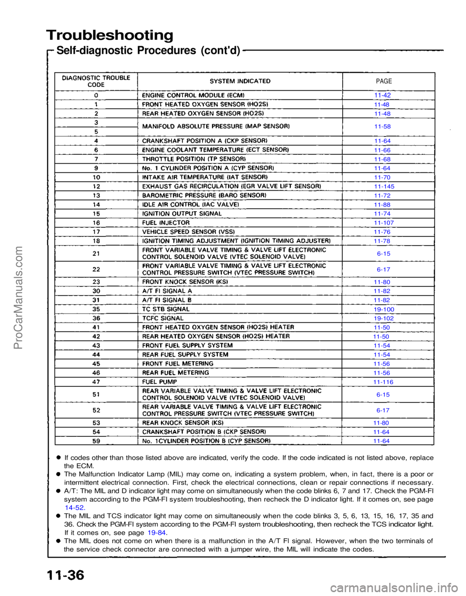
Self-diagnostic Procedures (cont'd)
If codes other than those listed above are indicated, verify the code. If the code indicated is not listed above, replace
the
ECM.
The Malfunction Indicator Lamp (MIL) may come on, indicating a system problem, when, in fact, there is a poor or
intermittent electrical connection. First, check the electrical connections, clean or repair connections if necessary.
A/T: The MIL and D indicator light may come on simultaneously when the code blinks 6, 7 and 17. Check the PGM-FI
system according to the PGM-FI system troubleshooting, then recheck the D indicator light. If it comes on, see page 14-52.
The MIL and TCS indicator light may come on simultaneously when the code blinks 3, 5, 6, 13, 15, 16, 17, 35 and
36.
Check
the
PGM-FI system according
to the
PGM-FI system
troubleshooting,
then
recheck
the TCS
indicator
light.
If it comes on, see page 19-84.
The MIL does not come on when there is a malfunction in the A/T Fl signal. However, when the two terminals of
the service check connector are connected with a jumper wire, the MIL will indicate the codes.
PAGE
11-42
11-48 11-48
11-58
11-64
11-66
11-68
11-64
11-70
11-145
11-72
11-88
11-74
11-107
11-76
11-78
6-15
6-17
11-80
11-82
11-82
19-100
19-102
11-50
11-50 11-54
11-54
11-56
11-56
11-116
6-15
6-17
11-80
11-64
11-64ProCarManuals.com
Page 1088 of 1640
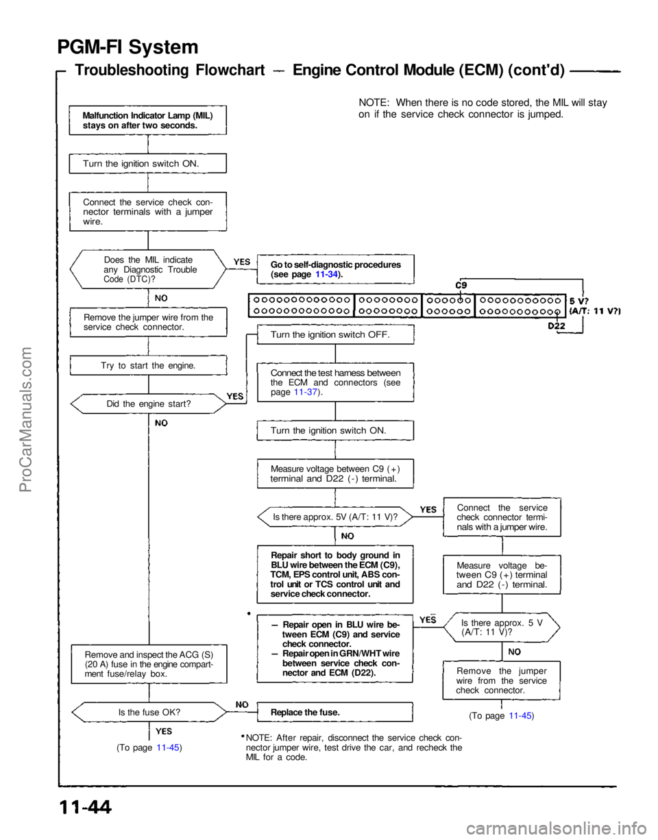
PGM-FI System
Troubleshooting Flowchart
Engine Control Module (ECM) (cont'd)
Malfunction Indicator Lamp (MIL) stays on after two seconds.
Turn the ignition switch ON.
Connect the service check con-
nector terminals with a jumper
wire.
Does the MIL indicate
any Diagnostic Trouble
Code (DTC)?
Remove the jumper wire from the
service check connector.
Try to start the engine.Did the engine start?
Remove and inspect the ACG (S) (20 A) fuse in the engine compart-
ment fuse/relay box.
Is the fuse OK?
(To page 11-45) Go to self-diagnostic procedures
(see page 11-34).
Turn the ignition switch OFF.
Connect the test harness between
the ECM and connectors (see page 11-37).
Turn the ignition switch ON.
Measure voltage between C9 (+)
terminal and D22 (-) terminal.
Is there approx. 5V (A/T: 11 V)?
Repair short to body ground in
BLU wire between the ECM (C9),
TCM, EPS control unit, ABS con-
trol unit or TCS control unit and service check connector.
Repair open in BLU wire be-
tween ECM (C9) and service check connector.
Repair open in GRN/WHT wire
between service check con-
nector and ECM (D22).
Replace the fuse.
NOTE: After repair, disconnect the service check con-
nector jumper wire, test drive the car, and recheck the
MIL for a code. NOTE: When there is no code stored, the MIL will stay
on if the service check connector is jumped.
Connect the service
check connector termi-
nals with a jumper wire.
Measure voltage be-
tween C9 (+) terminal
and D22 (-) terminal.
Is there approx. 5 V(A/T:
11 V)?
Remove the jumper
wire from the service
check connector.
(To page 11-45)ProCarManuals.com