Page 1089 of 1640
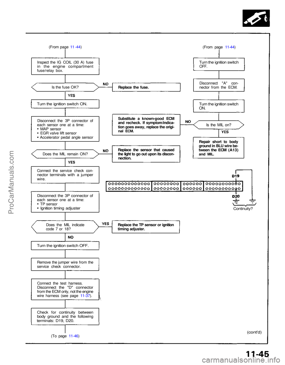
(From page 11 -44)
Inspect the IG COIL (30 A) fuse
in the engine compartment
fuse/relay box.
Is the fuse OK?
Turn the ignition switch ON.
Disconnect the 3P connector of
each sensor one at a time: MAP sensor
EGR
valve
lift
sensor
Accelerator pedal angle sensor
Does the MIL remain ON?
Connect the service check con-
nector terminals with a jumper
wire.
Disconnect the 3P connector of
each sensor one at a time:
TP sensor
Ignition timing adjuster
Does the MIL indicate
code 7 or 18?
Turn the ignition switch OFF.
Remove the jumper wire from the
service check connector.
Connect the test harness.
Disconnect the "D" connector
from the ECM only, not the engine
wire harness (see page 11-37).
Check for continuity between
body ground and the following
terminals: D19, D20.
(To page 11-46) Replace the fuse.
Substitute a known-good ECM
and recheck. If symptom/indica-
tion goes away, replace the origi-
nal
ECM.
Replace the sensor that caused
the light to go out upon its discon- nection.
Replace the TP sensor or ignition
timing adjuster. (From page 11-44)
Turn the ignition switch
OFF.
Disconnect "A" con-
nector from the ECM.
Turn the ignition switch
ON.
Is the MIL on?
Repair short to body
ground in BLU wire be-
tween the ECM (A13)
and
MIL.
Continuity?
(cont'd)ProCarManuals.com
Page 1109 of 1640
System Description
The fuel supply system consists of a fuel tank, in-tank high pressure fuel pump, fuel pump relay, fuel pump
resistor, PGM-FI main relay, fuel filter, fuel pressureregulator, fuel injectors and fuel injector resistor.
This system delivers pressure-regulated fuel to the fuel injectors and cuts the fuel delivery when the engine is
not running. Fuel Pressure
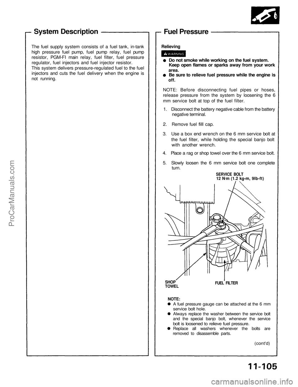
Relieving
Do not smoke while working on the fuel system.
Keep open flames or sparks away from your work
area.
Be sure to relieve fuel pressure while the engine is
off.
NOTE: Before disconnecting fuel pipes or hoses,
release pressure from the system by loosening the 6
mm service bolt at top of the fuel filter. 1. Disconnect the battery negative cable from the battery negative terminal.
2.
Remove
fuel
fill
cap.
3. Use a box end wrench on the 6 mm service bolt at the fuel filter, while holding the special banjo boltwith another wrench.
4. Place a rag or shop towel over the 6 mm service bolt.
5. Slowly loosen the 6 mm service bolt one complete turn.
SERVICE BOLT
12 N .
m (1.2 kg-m, 9lb-ft)
SHOP
TOWEL
FUEL FILTER
NOTE:
A fuel pressure gauge can be attached at the 6 mm
service bolt hole.
Always replace the washer between the service bolt
and the special banjo bolt, whenever the service
bolt is loosened to relieve fuel pressure.
Replace all washers whenever the bolts are
removed to disassemble parts.
(cont'd)ProCarManuals.com
Page 1110 of 1640
Fuel Supply System
Fuel Pressure (cont'd)
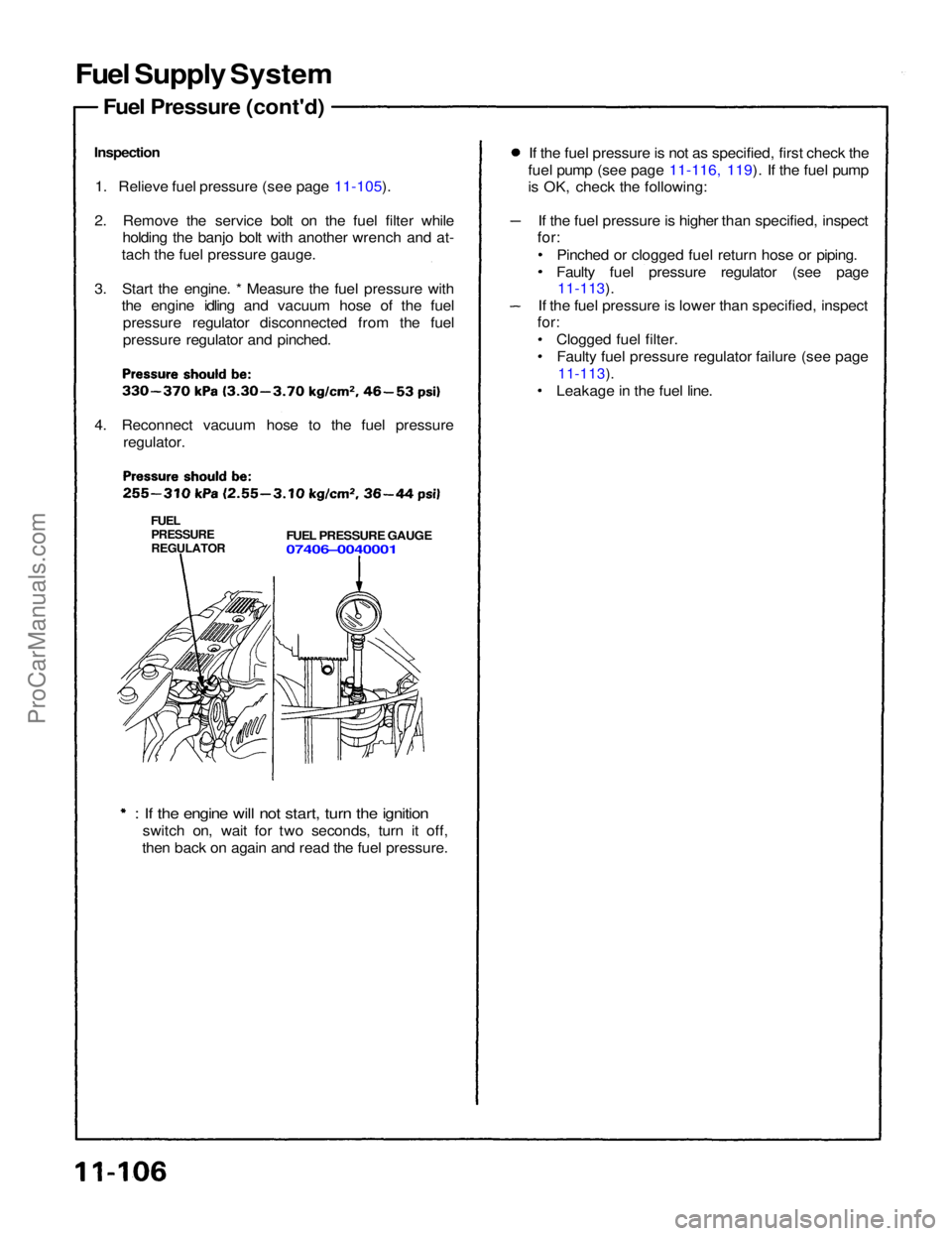
Inspection 1. Relieve fuel pressure (see page 11-105).
2. Remove the service bolt on the fuel filter while holding the banjo bolt with another wrench and at-
tach the fuel pressure gauge.
3. Start the engine. * Measure the fuel pressure with the engine idling and vacuum hose of the fuel
pressure regulator disconnected from the fuel
pressure regulator and pinched.
4. Reconnect vacuum hose to the fuel pressure regulator.
FUEL
PRESSURE
REGULATOR
FUEL PRESSURE GAUGE
07406–0040001
: If the engine will not start, turn the ignition
switch on, wait for two seconds, turn it off,
then back on again and read the fuel pressure. If the fuel pressure is not as specified, first check the
fuel pump (see page 11-116, 119). If the fuel pump
is OK, check the following:
If the fuel pressure is higher than specified, inspect
for:
Pinched or clogged fuel return hose or piping.
Faulty fuel pressure regulator (see page
11-113).
If the fuel pressure is lower than specified, inspect
for:
Clogged fuel filter.Faulty fuel pressure regulator failure (see page
11-113).
Leakage in the fuel line.ProCarManuals.com
Page 1114 of 1640
Fuel Pressure Regulator
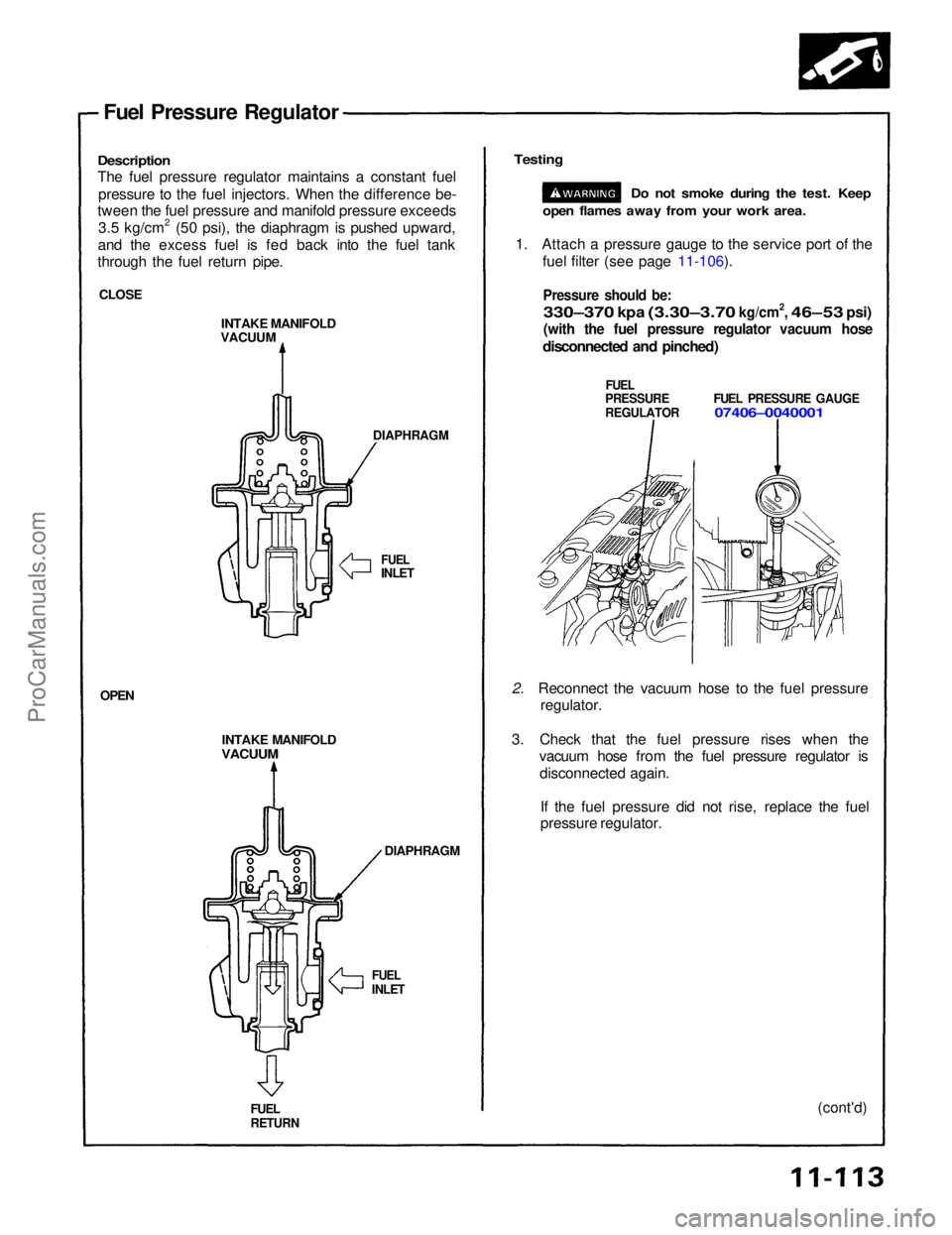
Description
The fuel pressure regulator maintains a constant fuel pressure to the fuel injectors. When the difference be-
tween the fuel pressure and manifold pressure exceeds
3.5 kg/cm2 (50 psi), the diaphragm is pushed upward,
and the excess fuel is fed back into the fuel tank
through the fuel return pipe.
CLOSE INTAKE MANIFOLD
VACUUM
DIAPHRAGM
FUEL
INLET
INTAKE MANIFOLD
VACUUM
DIAPHRAGM
OPEN
FUEL
RETURN
FUEL
INLET
(cont'd)
2. Reconnect the vacuum hose to the fuel pressure
regulator.
3. Check that the fuel pressure rises when the vacuum hose from the fuel pressure regulator is
disconnected again.
If the fuel pressure did not rise, replace the fuel
pressure regulator.
Testing
Do not smoke during the test. Keep
open flames away from your work area.
1. Attach a pressure gauge to the service port of the fuel filter (see page 11-106).
Pressure should be:
330–370
kpa
(3.30–3.70
kg/cm2,
46–53
psi)
(with the fuel pressure regulator vacuum hose
disconnected and pinched)
FUEL
PRESSURE FUEL PRESSURE GAUGE
REGULATOR
07406–0040001ProCarManuals.com
Page 1115 of 1640
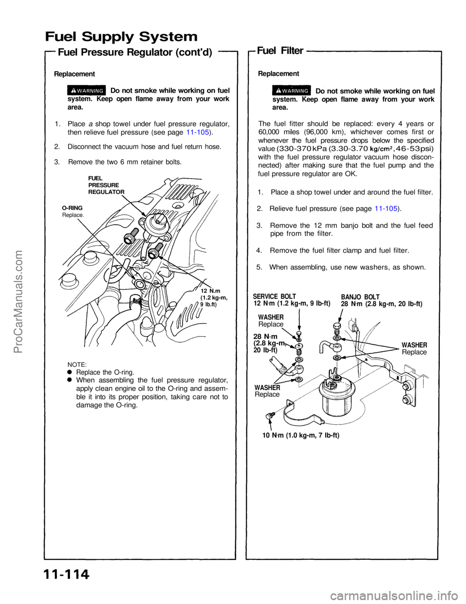
Fuel Supply System
Fuel Pressure Regulator (cont'd)
Replacement
Do not smoke while working on fuel Fuel Filter
Replacement
Do not smoke while working on fuel
The fuel fitter should be replaced: every 4 years or 60,000 miles (96,000 km), whichever comes first or
whenever the fuel pressure drops below the specified value
(330-370
kPa
(3.30-3.70
,
46-53
psi)
with the fuel pressure regulator vacuum hose discon-
nected) after making sure that the fuel pump and the
fuel pressure regulator are OK.
1. Place a shop towel under and around the fuel filter.
2. Relieve fuel pressure (see page 11-105).
3. Remove the 12 mm banjo bolt and the fuel feed pipe from the filter.
4. Remove the fuel filter clamp and fuel filter. 5. When assembling, use new washers, as shown.
1. Place a shop towel under fuel pressure regulator,
then relieve fuel pressure (see page 11-105).
2. Disconnect the vacuum hose and fuel return hose.
3. Remove the two 6 mm retainer bolts.
FUEL
PRESSURE
REGULATOR
O-RING
Replace.
NOTE:
12 N.m
(1.2 kg-m,
9 Ib.ft)
SERVICE BOLT
12 N .
m (1.2 kg-m, 9 Ib-ft)
BANJO BOLT
28 N
.
m (2.8 kg-m, 20 Ib-ft)
WASHER
Replace
28 N·m
(2.8 kg-m,
20 Ib-ft)
WASHER
Replace
10 N .
m (1.0 kg-m, 7 Ib-ft)
WASHER
Replace
system. Keep open flame away from your work
area.
system. Keep open flame away from your work
area.
Replace the O-ring.
When assembling the fuel pressure regulator,
apply clean engine oil to the O-ring and assem-ble it into its proper position, taking care not to
damage the O-ring.ProCarManuals.com
Page 1116 of 1640
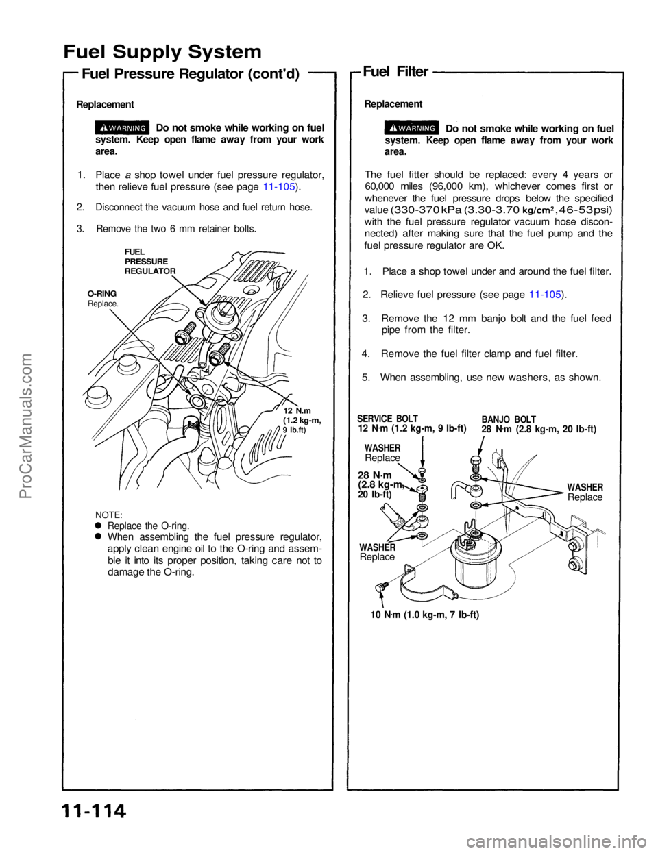
Fuel Supply System
Fuel Pressure Regulator (cont'd)
Replacement
Do not smoke while working on fuel Fuel Filter
Replacement
Do not smoke while working on fuel
The fuel fitter should be replaced: every 4 years or 60,000 miles (96,000 km), whichever comes first or
whenever the fuel pressure drops below the specified value
(330-370
kPa
(3.30-3.70
,
46-53
psi)
with the fuel pressure regulator vacuum hose discon-
nected) after making sure that the fuel pump and the
fuel pressure regulator are OK.
1. Place a shop towel under and around the fuel filter.
2. Relieve fuel pressure (see page 11-105).
3. Remove the 12 mm banjo bolt and the fuel feed pipe from the filter.
4. Remove the fuel filter clamp and fuel filter. 5. When assembling, use new washers, as shown.
1. Place a shop towel under fuel pressure regulator,
then relieve fuel pressure (see page 11-105).
2. Disconnect the vacuum hose and fuel return hose.
3. Remove the two 6 mm retainer bolts.
FUEL
PRESSURE
REGULATOR
O-RING
Replace.
NOTE:
12 N.m
(1.2 kg-m,
9 Ib.ft)
SERVICE BOLT
12 N .
m (1.2 kg-m, 9 Ib-ft)
BANJO BOLT
28 N
.
m (2.8 kg-m, 20 Ib-ft)
WASHER
Replace
28 N·m
(2.8 kg-m,
20 Ib-ft)
WASHER
Replace
10 N .
m (1.0 kg-m, 7 Ib-ft)
WASHER
Replace
system. Keep open flame away from your work
area.
system. Keep open flame away from your work
area.
Replace the O-ring.
When assembling the fuel pressure regulator,
apply clean engine oil to the O-ring and assem-ble it into its proper position, taking care not to
damage the O-ring.ProCarManuals.com
Page 1178 of 1640
Description
Electronic Control System (cont'd)
TRANSMISSION CONTROL MODULE (TCM)
ENGINE
CONTROL
MODULE
(ECM) Shift Control
Lock-up
Control
TCS Control Unit
EPS Control Unit Engine RPM
Air Conditioning Signal Brake Switch Signal
Vehicle Speed Sensor Signal
Mainshaft Speed Sensor Signal
Countershaft Speed Sensor Signal
Self-Diagnosis
Function
Self-Diagnosis Indicator
INTERLOCK
CONTROL UNIT
Lock-up Control Solenoid
Valve B
Lock-up Control Solenoid
Valve A Shift Control Solenoid
Valve B
Shift Control Solenoid
Valve A
Linear Solenoid
Throttle Position
Sensor Signal
Engine Coolant
Temperature
Sensor Signal
Accet Pedal
Angle Signal
Service Check
Connector
ProCarManuals.com
Page 1208 of 1640
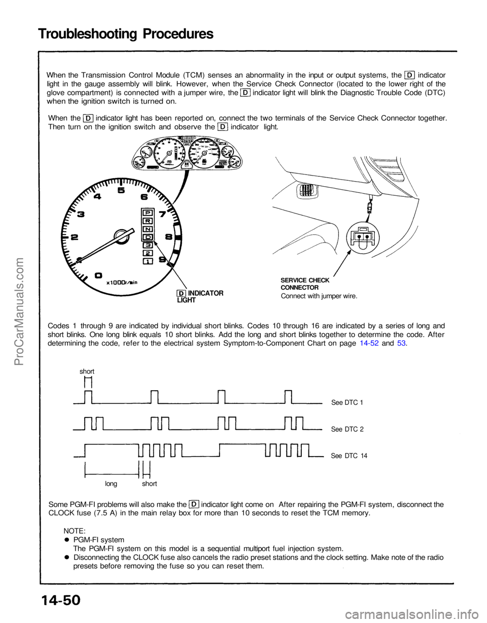
Troubleshooting Procedures
When the Transmission Control Module (TCM) senses an abnormality in the input or output systems, the indicator
light in the gauge assembly will blink. However, when the Service Check Connector (located to the lower right of the glove compartment) is connected with a jumper wire, the indicator light will blink the Diagnostic Trouble Code (DTC)
when the ignition switch is turned on.
When the indicator light has been reported on, connect the two terminals of the Service Check Connector together.
Then turn on the ignition switch and observe the indicator light.
Codes 1 through 9 are indicated by individual short blinks. Codes 10 through 16 are indicated by a series of long and
short blinks. One long blink equals 10 short blinks. Add the long and short blinks together to determine the code. After
determining the code, refer to the electrical system Symptom-to-Component Chart on page 14-52 and 53. SERVICE CHECK
CONNECTOR
Connect with jumper wire.
INDICATOR
Some PGM-FI problems will also make the indicator light come on After repairing the PGM-FI system, disconnect the
CLOCK fuse (7.5 A) in the main relay box for more than 10 seconds to reset the TCM memory.
long short
See DTC 1
See DTC 2
See DTC 14
LIGHT
short
PGM-FI system
The PGM-FI system on this model is a sequential multiport fuel injection system. Disconnecting the CLOCK fuse also cancels the radio preset stations and the clock setting. Make note of the radio
presets before removing the fuse so you can reset them.
NOTE:ProCarManuals.com