Page 1366 of 1640
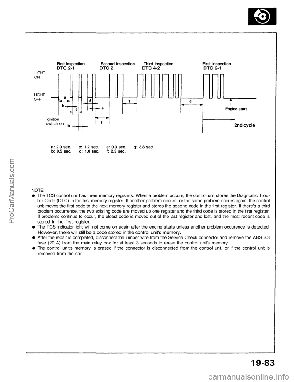
The TCS control unit has three memory registers. When a problem occurs, the control unit stores the Diagnostic Trou-
ble Code (DTC) in the first memory register. If another problem occurs, or the same problem occurs again, the control
unit moves the first code to the next memory register and stores the second code in the first register. If there's a thirdproblem occurrence, the two existing code are moved up one register and the third code is stored in the first register.
If problems continue to occur, the oldest code is moved out of the last register and lost, and the most recent code is
stored in the first register. The TCS indicator light will not come on again after the engine starts unless another problem occurence is detected.
However, there will still be a code stored in the control unit's memory.
After the repair is completed, disconnect the jumper wire from the Service Check connector and remove the ABS 2.3
fuse (20 A) from the main relay box for at least 3 seconds to erase the control unit's memory. The control unit's memory is erased if the connector is disconnected from the control unit, or if the control unit is
removed from the car.
NOTE:
a: 2.0
sec.
c: 1.2
sec.
e: 0.3
sec.
g: 3.8
sec.
b: 0.5
sec.
d: 1.0
sec.
f: 2.5
sec.
Ignition
switch on
LIGHT
ON
LIGHT
OFF
First inspection Second inspection Third inspection First inspection
DTC 2-1 DTC 2 DTC 4-2 DTC 2-1
Engine start2nd cycle
ProCarManuals.com
Page 1393 of 1640
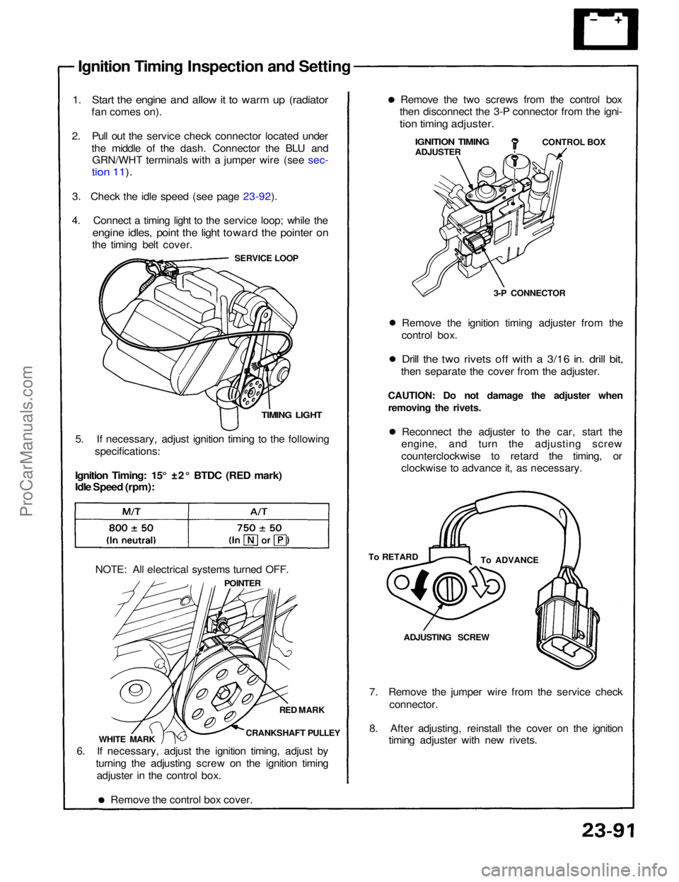
Ignition Timing Inspection and Setting
1. Start the engine and allow it to warm up (radiator
fan comes on).
2. Pull out the service check connector located under the middle of the dash. Connector the BLU andGRN/WHT terminals with a jumper wire (see sec-
tion 11).
3. Check the idle speed (see page 23-92).
4. Connect a timing light to the service loop; while the
engine idles, point the light toward the pointer on
the timing belt cover.
SERVICE LOOP
TIMING LIGHT
5. If necessary, adjust ignition timing to the following specifications:
Ignition Timing: 15° ±2° BTDC (RED mark)
Idle Speed (rpm):
NOTE: All electrical systems turned OFF. POINTER
RED MARK
CRANKSHAFT PULLEY
WHITE MARK
6. If necessary, adjust the ignition timing, adjust by turning the adjusting screw on the ignition timingadjuster in the control box.
Remove the control box cover. 7. Remove the jumper wire from the service check
connector.
8. After adjusting, reinstall the cover on the ignition timing adjuster with new rivets.ADJUSTING SCREW
To ADVANCE
To RETARD Reconnect the adjuster to the car, start the
engine, and turn the adjusting screw
counterclockwise to retard the timing, or
clockwise to advance it, as necessary.
CAUTION: Do not damage the adjuster when
removing the rivets. Remove the ignition timing adjuster from the
control box.
Drill the two rivets off with a 3/16 in. drill bit,
then separate the cover from the adjuster. 3-P CONNECTORCONTROL BOX
IGNITION TIMING
ADJUSTER
Remove the two screws from the control box
then disconnect the 3-P connector from the igni-
tion timing adjuster.ProCarManuals.com
Page 1457 of 1640
Warning/Caution Label Locations
A: CABLE REEL CAUTION A
CAUTION:
BEFORE INSTALLING CABLE REEL
CENTER THE FRONT WHEELS.
ALIGN THE MARKS.
READ SERVICE MANUAL.
B: CABLE REEL CAUTION B
CAUTION:
NO SERVICEABLE PARTS INSIDE; DO NOT
DISASSEMBLE OR TAMPER.
C: STEERING WHEEL WARNING
(SUN VISOR)
WARNING
BEFORE INSTALLING STEERING WHEEL:
CENTER THE FRONT WHEELS.
ALIGN THE MARKS. (CABLE REEL)
READ SERVICE MANUAL.
D: BULKHEAD WARNING
WARNING
THIS VEHICLE IS EQUIPPED WITH A DRIVER
AIRBAG AS A SUPPLEMENTAL RESTRAINT
SYSTEM. (SRS)
ALL SRS ELECTRICAL WIRING AND CONNECTORS
ARE COLORED YELLOW.
DO NOT USE ELECTRICAL TEST EQUIPMENT ON
THESE CIRCUITS. TAMPERING WITH OR DISCON-
NECTING THE SRS WIRING COULD RESULT IN
ACCIDENTAL FIRING OF THE INFLATOR OR MAKE
THE SYSTEM INOPERATIVE, WHICH MAY RESULT
IN SERIOUS INJURY.ProCarManuals.com
Page 1458 of 1640
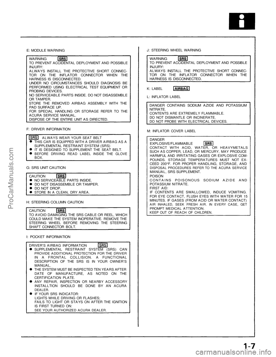
E: MODULE WARNING
J: STEERING WHEEL WARNING
WARNING
TO PREVENT ACCIDENTAL DEPLOYMENT AND POSSIBLE
INJURY:
ALWAYS INSTALL THE PROTECTIVE SHORT CONNEC-
TOR ON THE INFLATOR CONNECTOR WHEN THE
HARNESS IS DISCONNECTED.
UNDER NO CIRCUMSTANCES SHOULD DIAGNOSIS BE
PERFORMED USING ELECTRICAL TEST EQUIPMENT OR
PROBING DEVICES.
NO SERVICEABLE PARTS INSIDE. DO NOT DISASSEMBLE
OR TAMPER.
STORE THE REMOVED AIRBAG ASSEMBLY WITH THE
PAD SURFACE UP.
FOR SPECIAL HANDLING OR STORAGE REFER TO THE
ACURA SERVICE MANUAL.
DISPOSE OF THE ENTIRE UNIT AS DIRECTED.
F: DRIVER INFORMATION
ALWAYS WEAR YOUR SEAT BELT
THIS CAR IS EQUIPPED WITH A DRIVER AIRBAG AS A
SUPPLEMENTAL RESTRAINT SYSTEM (SRS)
IT IS DESIGNED TO SUPPLEMENT THE SEAT BELT.
BEFORE DRIVING READ LABEL INSIDE THE GLOVE
BOX.
K: LABEL
WARNING
TO PREVENT ACCIDENTAL DEPLOYMENT AND POSSIBLE
INJURY:
ALWAYS INSTALL THE PROTECTIVE SHORT CONNEC-
TOR ON THE INFLATOR CONNECTOR WHEN THE
HARNESS IS DISCONNECTED.
L: INFLATOR LABEL
DANGER CONTAINS SODIUM AZIDE AND POTASSIUM
NITRATE.
CONTENTS ARE EXTREMELY FLAMMABLE.
DO NOT DISMANTLE OR INCINERATE.
DO NOT PROBE WITH ELECTRICAL DEVICES.
M: INFLATOR COVER LABEL
DANGER
EXPLOSIVE/FLAMMABLE
CONTACT WITH ACID, WATER, OR HEAVYMETALS
SUCH AS COPPER, LEAD, OR MERCURY, MAY PRODUCE
HARMFUL AND IRRITATING GASES OR EXPLOSIVE COM-
POUNDS. STORAGE TEMPERATURES MUST NOT EX-
CEED 200°F. FOR PROPER HANDLING, STORAGE, AND
DISPOSAL PROCEDURES REFER TO THE ACURA SERVICE
MANUAL, SRS SUPPLEMENT.
POISON
CONTAINS POISONOUS SODIUM AZIDE AND
POTASSIUM NITRATE.
FIRST AID:
IF CONTENTS ARE SWALLOWED, INDUCE VOMITING.
FOR EYE CONTACT, FLUSH EYES WITH WATER FOR 15
MINUTES. IF GASES (FROM ACID OR WATER CONTACT)
AIR INHALED, SEEK FRESH AIR. IN EVERY CASE, GET
PROMPT MEDICAL ATTENTION.
KEEP OUT OF REACH OF CHILDREN.
G: SRS UNIT CAUTION
CAUTION
NO SERVICEABLE PARTS INSIDE.
DO NOT DISASSEMBLE OR TAMPER.
DO NOT DROP.
STORE IN A CLEAN, DRY AREA.
H: STEERING COLUMN CAUTION
CAUTION
I: POCKET INFORMATION
TO AVOID DAMAGING THE SRS CABLE OR REEL, WHICH
COULD MAKE THE SYSTEM INOPERATIVE. REMOVE THE
STEERING WHEEL BEFORE REMOVING THE STEERING
SHAFT CONNECTOR BOLT.
DRIVER'S AIRBAG INFORMATION
SUPPLEMENTAL RESTRAINT SYSTEM (SRS) CAN
PROVIDE ADDITIONAL PROTECTION FOR THE DRIVER
IN A FRONTAL COLLISION. A FUNCTIONAL
DESCRIPTION OF THE SRS IS IN YOUR OWNER'S
MANUAL.
THE SYSTEM MUST BE INSPECTED TEN YEARS AFTER
DATE OF MANUFACTURE, AS NOTED ON THE
CERTIFICATION PLATE.
ANY REPAIR, INSPECTION OR NEARBY ACCESSORY
INSTALLTION SHOULD BE DONE BY AN ACURA
DEALER.
IF YOUR SRS INDICATOR:
LIGHTS WHILE DRIVING OR FLASHES;
FAILS TO LIGHT OR STAYS ON AFTER THE IGNITION
IS FIRST TURNED ON:
SEE YOUR AUTHORIZED ACURA DEALER.ProCarManuals.com
Page 1460 of 1640
SEC
&
PAGE
NOTES
11-112
11-84
11-125
11-128 11-135
23-89
11-134
6-54 ('91-'93) 11-4,
97
11-4
23-94 8-4
8-5
23-107
10-2, 3
10-5
13-3
14-94 ('91-'93)
R = Replace I = Inspect After inspection, clean, adjust, repair or replace if necessary.
Check oil and coolant level at each fuel stop.Under severe driving conditions, service these items more often. For cars sold in California, this service is recommended only; other areas, it is required.
Replace every 6 years or 60,000 miles (96,000 km), whichever comes first.
Tension adjustment only.
Thereafter, replace every 2 years or 30,000 miles (48,000 km), whichever comes first.ProCarManuals.com
Page 1461 of 1640
R = Replace I = Inspect After inspection, clean, adjust, repair or replace if necessary.
NOTES
SEC
&
PAGE
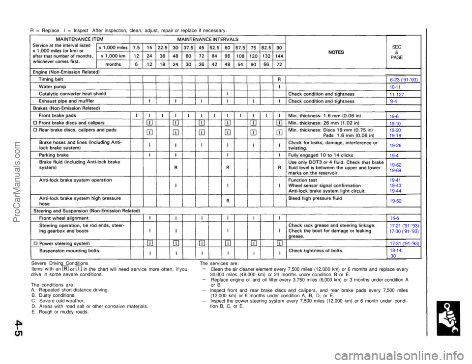
Severe Driving Conditions Items with an orin the chart will need service more often, if you
drive in some severe conditions.
The conditions are:
A. Repeated short distance driving.
B. Dusty conditions.
C. Severe cold weather.
D. Areas with road salt or other corrosive materials.
E. Rough or muddy roads. The services are:
Clean the air cleaner element every 7,500 miles (12,000 km) or 6 months and replace every
30,000 miles (48,000 km) or 24 months under condition B or E. Replace engine oil and oil filter every 3,750 miles (6,000 km) or 3 months under condition A
or B.
Inspect front and rear brake discs and calipers, and rear brake pads every 7,500 miles (12,000 km) or 6 months under condition A, B, D, or E.
Inspect the power steering system every 7,500 miles (12,000 km) or 6 month under condi-
tion B, C, or E. 6-23 ('91-'93)10-11
11-127
9-4
19-6
19-10
19-20
19-18
19-26
19-4
19-62
19-69
19-41
19-43
19-44
19-62
18-6
17-21 ('91-'93)
17-30 ('91-'93)
17-31 ('91-'93)
18-14,
30
ProCarManuals.com
Page 1477 of 1640
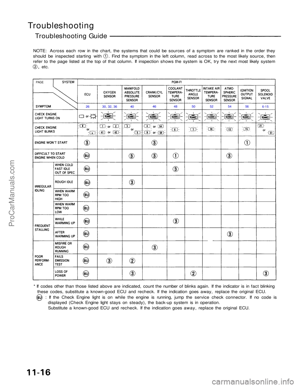
Troubleshooting
Troubleshooting Guide
NOTE: Across each row in the chart, the systems that could be sources of a symptom are ranked in the order they should be inspected starting with . Find the symptom in the left column, read across to the most likely source, then
refer to the page listed at the top of that column. If inspection shows the system is OK, try the next most likely system
,
etc.
* If codes other than those listed above are indicated, count the number of blinks again. If the indicator is in fact blinking these codes, substitute a known-good ECU and recheck. If the indication goes away, replace the original ECU. : If the Check Engine light is on while the engine is running, jump the service check connector. If no code is
displayed (Check Engine light stays on steady), the back-up system is in operation.
Substitute a known-good ECU and recheck. If the indication goes away, replace the original ECU.
PAGE
26
30, 32, 36
40
46
48
50
52
54
56
6-15ProCarManuals.com
Page 1501 of 1640
System Description
Fuel Pressure
The fuel supply system consists of a fuel tank, in-tank high pressure fuel pump, fuel pump relay, fuel pump
resistor, main relay, fuel filter, pressure regulator, injec-
tors and injector resistor.
This system delivers pressure regulated fuel to the in-
jectors and cuts the fuel delivery when the engine is not
running.
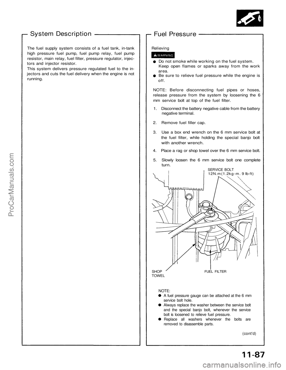
Relieving
Do not smoke while working on the fuel system.
Keep open flames or sparks away from the work
area.
Be sure to relieve fuel pressure while the engine is
off.
NOTE: Before disconnecting fuel pipes or hoses,
release pressure from the system by loosening the 6
mm service bolt at top of the fuel filter.
1. Disconnect the battery negative cable from the battery negative terminal.
2. Remove fuel filler cap.
3. Use a box end wrench on the 6 mm service bolt at the fuel filter, while holding the special banjo bolt
with another wrench.
4. Place a rag or shop towel over the 6 mm service bolt.
5. Slowly loosen the 6 mm service bolt one complete
turn.
SERVICE BOLT
12N.m(1.2kg-m. 9 Ib-ft)
SHOP
TOWEL
FUEL FILTER
NOTE:
A fuel pressure gauge can be attached at the 6 mm
service bolt hole.
Always replace the washer between the service bolt
and the special banjo bolt, whenever the service
bolt is loosened to relieve fuel pressure.
Replace all washers whenever the bolts are
removed to disassemble parts.
(cont'd)
ProCarManuals.com