Page 1505 of 1640
Pressure Regulator
Description
The fuel pressure regulator maintains a constant fuel
pressure to the injectors. When the difference between
the fuel pressure and manifold pressure exceeds 3.5
kg/cm2 (50 psi), the diaphragm is pushed upward, and
the excess fuel is fed back into the fuel tank through the
return line.
CLOSE
Testing
Do not smoke during the test. Keep
open flames away from your work area.
1. Attach a pressure gauge to the service port of the
fuel filter (page 11-88).
Pressure should be:
323-363
kpa
(3.30-3.70
kg/cm2.
46-53
psi)
(with the regulator vacuum hose disconnected)
PRESSURE FUEL PRESSURE GAUGE
REGULATOR
07406-0040001
INTAKE MANIFOLD
VACUUM
DIAPHRAGM
FUEL
INLET
2. Reconnect the vacuum hose to the pressure
regulator.
OPEN
INTAKE MANIFOLD
VACUUM
DIAPHRAGM
FUEL
INLET
(cont'd)ProCarManuals.com
Page 1507 of 1640
Fuel Filter
Replacement Do not smoke while working on fuel
system. Keep open flame away from work area.
The filter should be replaced: every 4 years or 60,000
miles (96,000 km), whichever comes first or whenever
the fuel pressure drops below the specified value
(323–363
kPa,
3.30–3.70
kg/cm2,
46–53
psi
with
the pressure regulator vacuum hose disconnected) after
making sure that the fuel pump and the pressure
regulator are OK.
1. Place a shop towel under and around the fuel filter.
2. Relieve fuel pressure (page 11-87).
3. Remove the 12 mm banjo bolt and the fuel feed
pipe from the filter.
4. Remove the fuel filter clamp and fuel filter.
5. When assembling, use new washers, as shown.
WASHER
Replace
WASHER
Replace
10 N·m(1.0 kg-m, 7 Ib-ft)
SERVICE BOLT
12 N·m (1.2 kg.m, 9 Ib-ft)
BANJO BOLT28 N·m (2.8 kg-m, 20 Ib-ft)
WASHER
Replace
28 N·m
(2.8
kg-m,
20 Ib-ft)ProCarManuals.com
Page 1509 of 1640

Fuel Supply System
Fuel Pump (cont'd)
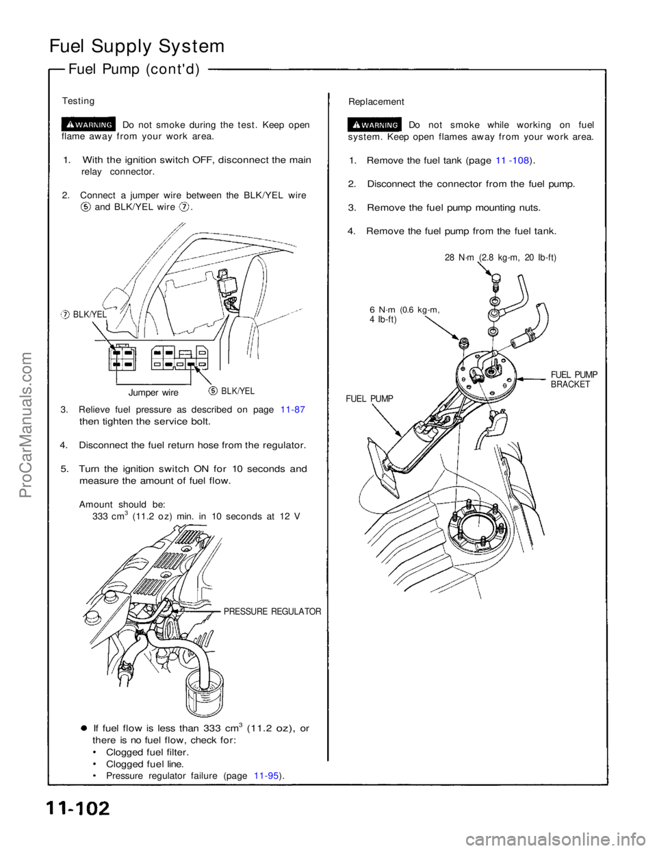
Testing Do not smoke during the test. Keep open
flame away from your work area.
1. With the ignition switch OFF, disconnect the main
relay connector.
2. Connect a jumper wire between the BLK/YEL wire and BLK/YEL wire .
Replacement
Do not smoke while working on fuel
system. Keep open flames away from your work area.
1. Remove the fuel tank (page 11 -108).
2. Disconnect the connector from the fuel pump.
3. Remove the fuel pump mounting nuts.
4. Remove the fuel pump from the fuel tank.
BLK/YEL
28 N·m (2.8 kg-m, 20 Ib-ft)
6 N·m
(0.6 kg-m,
4 Ib-ft)
BLK/YEL
Jumper wire
FUEL PUMP
FUEL PUMP
BRACKET
3. Relieve fuel pressure as described on page 11-87
then tighten the service bolt.
4. Disconnect the fuel return hose from the regulator.
5. Turn the ignition switch ON for 10 seconds and
measure the amount of fuel flow.
Amount should be: 333 cm3 (11.2 oz) min. in 10 seconds at 12 V
PRESSURE REGULATOR
If fuel flow is less than 333 cm3 (11.2 oz), or
there is no fuel flow, check for:
Clogged fuel filter.
Clogged fuel line.
Pressure regulator failure (page 11-95).ProCarManuals.com
Page 1570 of 1640

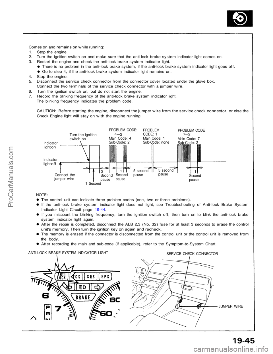
Comes on and remains on while running:
1. Stop the engine.
2. Turn the ignition switch on and make sure that the anti-lock brake system indicator light comes on.
3. Restart the engine and check the anti-lock brake system indicator light.
There is no problem in the anti-lock brake system, if the anti-lock brake system indicator light goes off. Go to step 4, if the anti-lock brake system indicator light remains on.
4. Stop the engine.
5. Disconnect the service check connector from the connector cover located under the glove box.
Connect the two terminals of the service check connector with a jumper wire.
6. Turn the ignition switch on, but do not start the engine. 7. Record the blinking frequency of the anti-lock brake system indicator light.
The blinking frequency indicates the problem code.
CAUTION: Before starting the engine, disconnect the jumper wire from the service check connector, or else the
Check Engine light will stay on with the engine running.
Turn the ignition
switch on
PROBLEM CODE:
4– 2
Main Code: 4
Sub-Code: 2
PROBLEM
CODE: 1
Main Code: 1
Sub-Code: none
PROBLEM CODE
7–2
Main Code: 7
Sub-Code: 2
Indicator
light on
Indicator
light off
Connect the
jumper wire
2
Second
pause
1
Second
pause
5 second
pause
5 second
pause
1
Second
pause
1 Second
NOTE:
The control unit can indicate three problem codes (one, two or three problems). If the anti-lock brake system indicator light does not light, see Troubleshooting of Anti-lock Brake System
Indicator Light Circuit page 19-44.
If you miscount the blinking frequency, turn the ignition switch off, then turn on to blink the anti-lock brake
system indicator light again. After the repair is completed, disconnect the ALB 2,3 (No. 32) fuse for at least 3 seconds to erase the control
unit's memory. Then turn the ignition key on again and recheck.
The memory is erased if the connector is disconnected from the control unit or the control unit is removed from
the body. After recording the main and sub-code (if applicable), refer to the Symptom-to-System Chart.
ANTI-LOCK BRAKE SYSTEM INDICATOR LIGHT
SERVICE CHECK CONNECTOR
JUMPER WIREProCarManuals.com
Page 1638 of 1640
Warning/Caution Labels
A: CABLE REEL CAUTION A
CAUTION:
BEFORE INSTALLING CABLE REEL
CENTER THE FRONT WHEELS.
ALIGN THE MARKS.
READ SERVICE MANUAL.
B: CABLE REEL CAUTION B
CAUTION:
NO SERVICEABLE PARTS INSIDE; DO NOT
DISASSEMBLE OR TAMPER.
C: STEERING WHEEL WARNING
WARNING
BEFORE INSTALLING STEERING WHEEL:
CENTER THE FRONT WHEELS.
ALIGN THE MARKS. (CABLE REEL)
READ SERVICE MANUAL.
D: BULKHEAD WARNING
WARNING
THIS VEHICLE IS EQUIPPED WITH A DRIVER
AIRBAG AS A SUPPLEMENTAL RESTRAINT
SYSTEM. (SRS)
ALL SRS ELECTRICAL WIRING AND CONNECTORS
ARE COLORED YELLOW.
DO NOT USE ELECTRICAL TEST EQUIPMENT ON
THESE CIRCUITS. TAMPERING WITH OR DISCON-
NECTING THE SRS WIRING COULD RESULT IN
ACCIDENTAL FIRING OF THE INFLATOR OR MAKE
THE SYSTEM INOPERATIVE, WHICH MAY RESULT
IN SERIOUS INJURY.
(SUN VISOR)ProCarManuals.com
Page 1639 of 1640

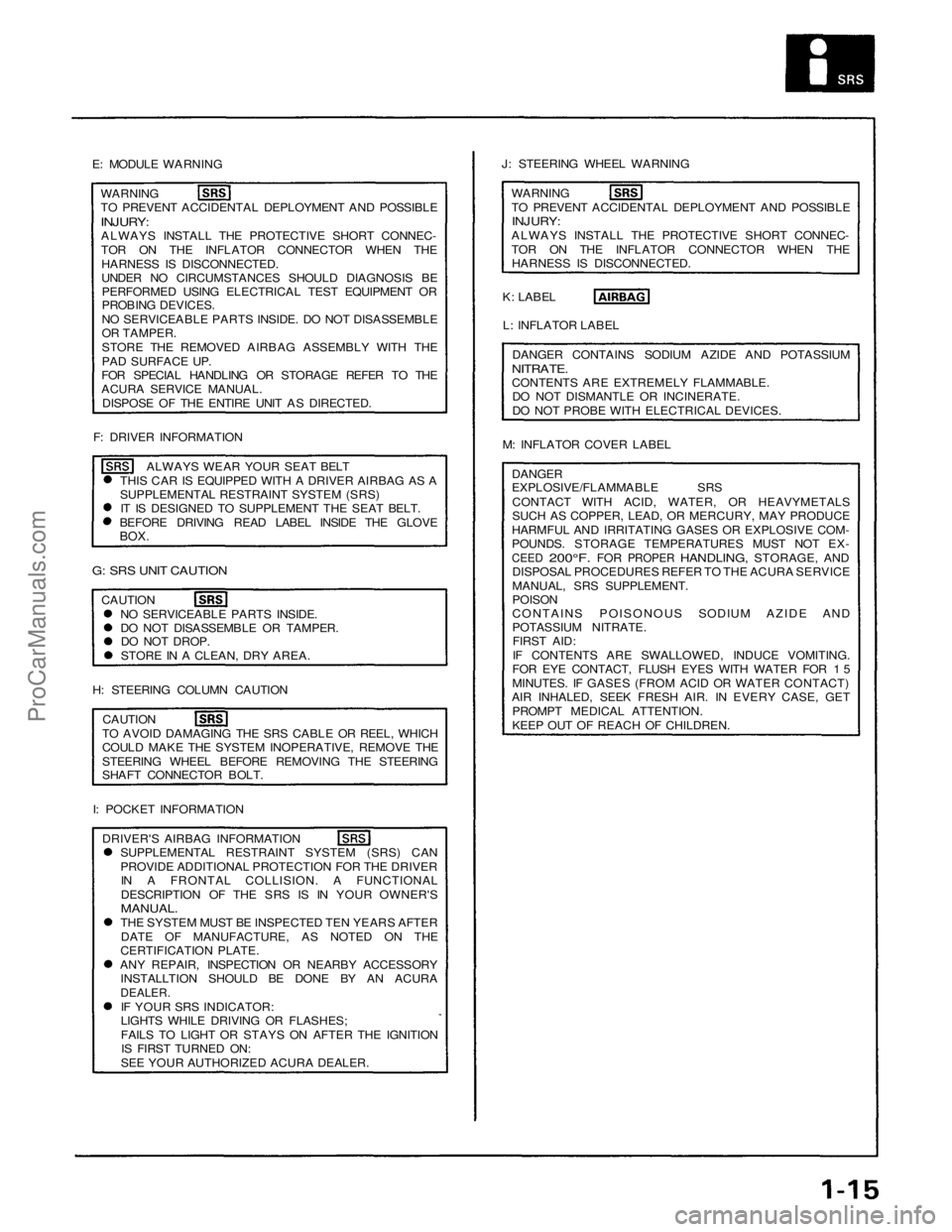
E: MODULE WARNING
WARNING
TO PREVENT ACCIDENTAL DEPLOYMENT AND POSSIBLE
INJURY:
ALWAYS INSTALL THE PROTECTIVE SHORT CONNEC-
TOR ON THE INFLATOR CONNECTOR WHEN THE
HARNESS IS DISCONNECTED.
UNDER NO CIRCUMSTANCES SHOULD DIAGNOSIS BE
PERFORMED USING ELECTRICAL TEST EQUIPMENT OR
PROBING DEVICES.
NO SERVICEABLE PARTS INSIDE. DO NOT DISASSEMBLE
OR TAMPER.
STORE THE REMOVED AIRBAG ASSEMBLY WITH THE
PAD SURFACE UP.
FOR SPECIAL HANDLING OR STORAGE REFER TO THE
ACURA SERVICE MANUAL.
DISPOSE OF THE ENTIRE UNIT AS DIRECTED.
F: DRIVER INFORMATION
ALWAYS WEAR YOUR SEAT BELT
THIS CAR IS EQUIPPED WITH A DRIVER AIRBAG AS A
SUPPLEMENTAL RESTRAINT SYSTEM (SRS)
IT IS DESIGNED TO SUPPLEMENT THE SEAT BELT.
BEFORE DRIVING READ LABEL INSIDE THE GLOVE
BOX.
G: SRS UNIT CAUTION
CAUTION
NO SERVICEABLE PARTS INSIDE.
DO NOT DISASSEMBLE OR TAMPER.
DO NOT DROP.
STORE IN A CLEAN, DRY AREA.
H: STEERING COLUMN CAUTION
CAUTION
TO AVOID DAMAGING THE SRS CABLE OR REEL, WHICH
COULD MAKE THE SYSTEM INOPERATIVE, REMOVE THE
STEERING WHEEL BEFORE REMOVING THE STEERING
SHAFT CONNECTOR BOLT.
I: POCKET INFORMATION
DRIVER'S AIRBAG INFORMATION
SUPPLEMENTAL RESTRAINT SYSTEM (SRS) CAN
PROVIDE ADDITIONAL PROTECTION FOR THE DRIVER
IN A FRONTAL COLLISION. A FUNCTIONAL
DESCRIPTION OF THE SRS IS IN YOUR OWNER'S
MANUAL.
THE SYSTEM MUST BE INSPECTED TEN YEARS AFTER
DATE OF MANUFACTURE, AS NOTED ON THE
CERTIFICATION PLATE.
ANY REPAIR, INSPECTION OR NEARBY ACCESSORY
INSTALLTION SHOULD BE DONE BY AN ACURA
DEALER.
IF YOUR SRS INDICATOR:
LIGHTS WHILE DRIVING OR FLASHES;
FAILS TO LIGHT OR STAYS ON AFTER THE IGNITION
IS FIRST TURNED ON:
SEE YOUR AUTHORIZED ACURA DEALER.
J: STEERING WHEEL WARNING
WARNING
TO PREVENT ACCIDENTAL DEPLOYMENT AND POSSIBLE
INJURY:
ALWAYS INSTALL THE PROTECTIVE SHORT CONNEC-
TOR ON THE INFLATOR CONNECTOR WHEN THE
HARNESS IS DISCONNECTED.
K: LABEL
L: INFLATOR LABEL
DANGER CONTAINS SODIUM AZIDE AND POTASSIUM
NITRATE.
CONTENTS ARE EXTREMELY FLAMMABLE.
DO NOT DISMANTLE OR INCINERATE.
DO NOT PROBE WITH ELECTRICAL DEVICES.
M: INFLATOR COVER LABEL
DANGER
EXPLOSIVE/FLAMMABLE SRS
CONTACT WITH ACID, WATER, OR HEAVYMETALS
SUCH AS COPPER, LEAD, OR MERCURY, MAY PRODUCE
HARMFUL AND IRRITATING GASES OR EXPLOSIVE COM-
POUNDS. STORAGE TEMPERATURES MUST NOT EX-
CEED
200°F.
FOR
PROPER
HANDLING,
STORAGE,
AND
DISPOSAL PROCEDURES REFER TO THE ACURA SERVICE
MANUAL, SRS SUPPLEMENT.
POISON
CONTAINS POISONOUS SODIUM AZIDE AND
POTASSIUM NITRATE.
FIRST AID:
IF CONTENTS ARE SWALLOWED, INDUCE VOMITING.
FOR EYE CONTACT, FLUSH EYES WITH WATER FOR 1 5
MINUTES. IF GASES (FROM ACID OR WATER CONTACT)
AIR INHALED, SEEK FRESH AIR. IN EVERY CASE, GET
PROMPT MEDICAL ATTENTION.
KEEP OUT OF REACH OF CHILDREN.ProCarManuals.com
Page 1640 of 1640
Ignition system
Component Location Index
IGNITION TIMING CONTROL SYSTEM
Troubleshooting, section 11Inspection and setting, page 23-91
Description, page 23-89
RADIO NOISE CONDENSER
Test, page 23-97
SPARK PLUGS (6)
Inspection, page 23-96
TACHOMETER CONNECTOR
(Engine revolution detected)
CYL/CRANK SENSOR
Troubleshooting, section 11 Replacement, section 5
IGNITION COILS (6) Removal, page 23-94 Test, page 23-95
IGNITER UNIT
Replacement, page 23-92Input Test, page 23-93 Troubleshooting, Section 11
SERVICE LOOPProCarManuals.com