1991 ACURA NSX service
[x] Cancel search: servicePage 1209 of 1640
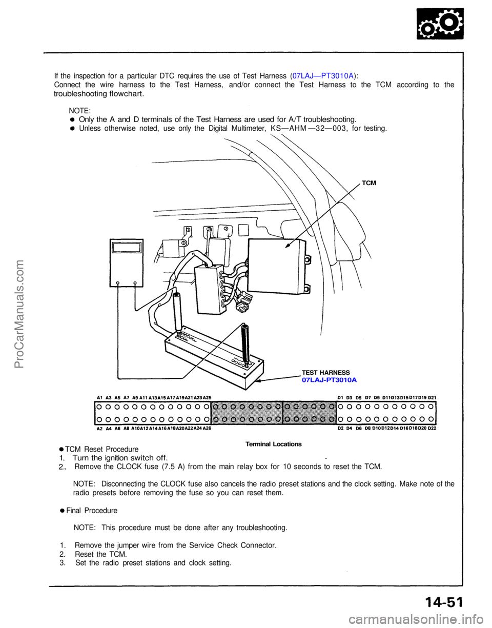
If the inspection for a particular DTC requires the use of Test Harness (07LAJ—PT3010A):
Connect the wire harness to the Test Harness, and/or connect the Test Harness to the TCM according to the
troubleshooting flowchart.
TCM
TEST HARNESS
Terminal Locations
TCM Reset Procedure
Turn the ignition switch off. -
, Remove the CLOCK fuse (7.5 A) from the main relay box for 10 seconds to reset the TCM.
1
2
NOTE: Disconnecting the CLOCK fuse also cancels the radio preset stations and the clock setting. Make note of the
radio presets before removing the fuse so you can reset them.
Final Procedure NOTE: This procedure must be done after any troubleshooting.
1. Remove the jumper wire from the Service Check Connector.
2. Reset the TCM. 3. Set the radio preset stations and clock setting.
Only the A and D terminals of the Test Harness are used for A/T troubleshooting.
Unless otherwise noted, use only the Digital Multimeter, KS—AHM —32—003, for testing.
07LAJ-PT3010A
NOTE:ProCarManuals.com
Page 1210 of 1640
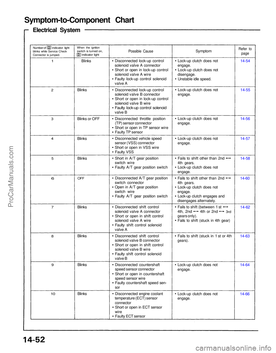
Symptom-to-Component Chart
Electrical System
Number of indicator light
blinks while Service Check
Connector is jumped.
When the ignition
switch is turned on,
indicator light
1
Blinks
Possible Cause
Symptom
Lock-up clutch does not
engage.
Lock-up clutch does not
disengage.
Unstable idle speed.
Refer to
page
14-54
14-55
14-56
14-57
14-58
14-60
14-62
14-63
14-64
14-66
Lock-up clutch does not
engage.
Lock-up clutch does not
engage.
Fails to shift (stuck in 1 st or 4th
gears).
Fails to shift other than 2nd
4th gears.
Lock-up clutch does not
engage.
Lock-up clutch engages and
disengages alternately. Fails to shift other than 2nd
4th gears.
Lock-up clutch does not
engage.
Lock-up clutch does not
engage.
Lock-up clutch does not
engage.
Lock-up clutch does not
engage.
Disconnected lock-up control
solenoid valve A connector Short or open in lock-up control
solenoid valve A wire
Faulty lock-up control solenoid
valve A
Disconnected lock-up control
solenoid valve B connector Short or open in lock-up control
solenoid valve B wire
Faulty lock-up control solenoid
valve B
Disconnected throttle position(TP) sensor connector
Short or open in TP sensor wire
Faulty TP sensor
Disconnected vehicle speed
sensor (VSS) connector
Short or open in VSS wire
Faulty VSS
Short in A/T gear position
switch wire
Faulty A/T gear position switch
Disconnected A/T gear position
switch connector
Open in A/T gear position
switch wire Faulty A/T gear position switch
Disconnected shift control
solenoid valve A connector Short or open in shift control
solenoid valve A wire
Faulty shift control solenoid
valve A
Disconnected shift control
solenoid valve B connector
Short or open in shift control
solenoid valve B wire
Faulty shift control solenoid
valve B
Disconnected countershaft
speed sensor connector
Short or open in countershaft
speed sensor wire Faulty countershaft speed sen-
sor
Disconnected engine coolant
temperature (ECT) sensor
connectorShort or open in ECT sensor
wire Faulty ECT sensor
Blinks
10
9
Blinks
Blinks
8
7
Blinks
6
OFF
Blinks
5
4
Blinks
3
Blinks or OFF Blinks
2
Fails to shift (between 1 st
4th,
2nd
4th or 2nd
3rd
gears only).
Fails to shift (stuck in 4th gear)ProCarManuals.com
Page 1211 of 1640
If a customer describes the symptoms for codes 3, 6, 11, 14 or 1 5 yet the indicator light is not blinking, it will
be necessary to recreate the symptom by test driving, and then checking the indicator light with the ignition
still
ON.
If the indicator light displays codes 1,2,3,8, 11, or 16, check first the No. 9, 13 and 18 and fuse before elec-
trical troubleshooting.
If any of the fuses have blown, repair them and then recheck. If the indicator light displays codes other than those listed above or stays lit continuously, the TCM is faulty.
Sometimes the indicator light and the Malfunction Indicator Lamp (MID/Check Engine light may come on
simultaneously. If so, check the PGM-FI system according to the number of blinks on the MIL/Check Engine light,
then reset the memory by removing the CLOCK fuse in the main relay box for more than 10 seconds. Drive the vehicle for several minutes at speed over 30 mph (50 km/h), then recheck the MIL/Check Engine light.PGM-FI system
The PGM-FI system on this model is a sequential multiport fuel injectin system.
The indicator light may comes on, indicating a system problem, when, in fact, there is a poor or intermittent
electrical connection. First, check the electrical connections, clean or repair connections if necessary.If the electrical readings are not as specified when using the test harness, check the test harness connections
before proceeding.
Disconnecting the CLOCK fuse also cancels the radio preset stations and the clock setting. Make note of the radio
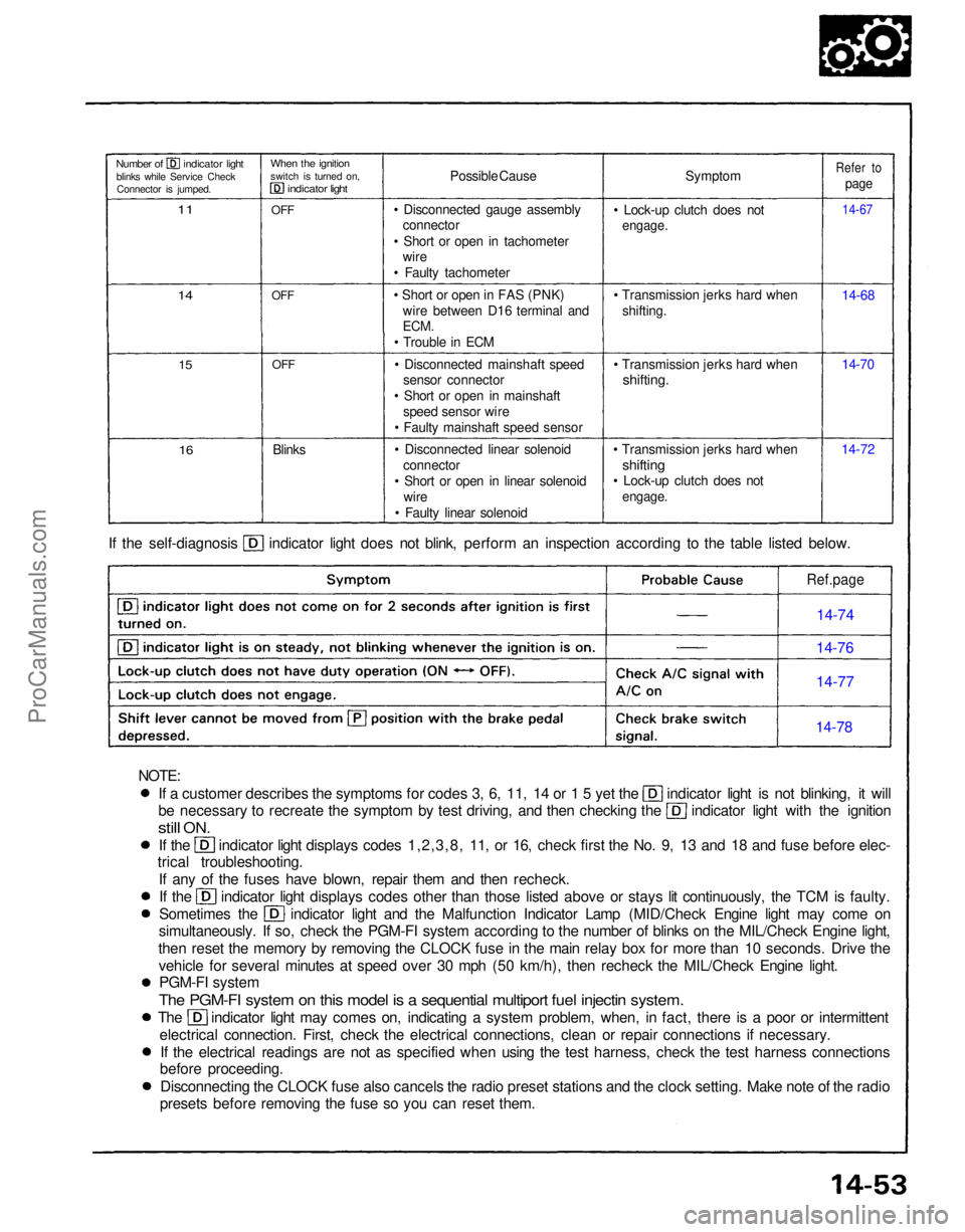
presets before removing the fuse so you can reset them. If the self-diagnosis indicator light does not blink, perform an inspection according to the table listed below.
Symptom
• Lock-up clutch does not
engage.
• Transmission jerks hard when shifting.
• Transmission jerks hard when
shifting.
• Transmission jerks hard when
shifting
• Lock-up clutch does not
engage.
14-7214-70 14-68
14-67
Refer to
page
Possible Cause
• Disconnected gauge assembly connector
• Short or open in tachometer wire
• Faulty tachometer
• Short or open in FAS (PNK) wire between D16 terminal and
ECM.
• Trouble in ECM
• Disconnected mainshaft speed sensor connector
• Short or open in mainshaft speed sensor wire
• Faulty mainshaft speed sensor
• Disconnected linear solenoid connector
• Short or open in linear solenoid wire
• Faulty linear solenoid
Blinks
OFF
OFF
OFF
When the ignition
switch is turned on,
indicator light
Number of indicator light
blinks while Service CheckConnector is jumped.
11
14
15
16
Ref.page
14-74
14-76
14-77
14-78
NOTE:ProCarManuals.com
Page 1259 of 1640
2ND GEAR SPACER
COTTER
FEELER GAUGE
2ND GEAR
3RD GEAR COTTER
2ND GEAR SPACER
6. After replacing the cotters, make sure that the
clearance is held within tolerance.
7. Remove the countershaft bearing from the trans-
mission housing. See page 14-144.
8. Assemble the countershaft including bearing and
all parts shown to on page 14-124.
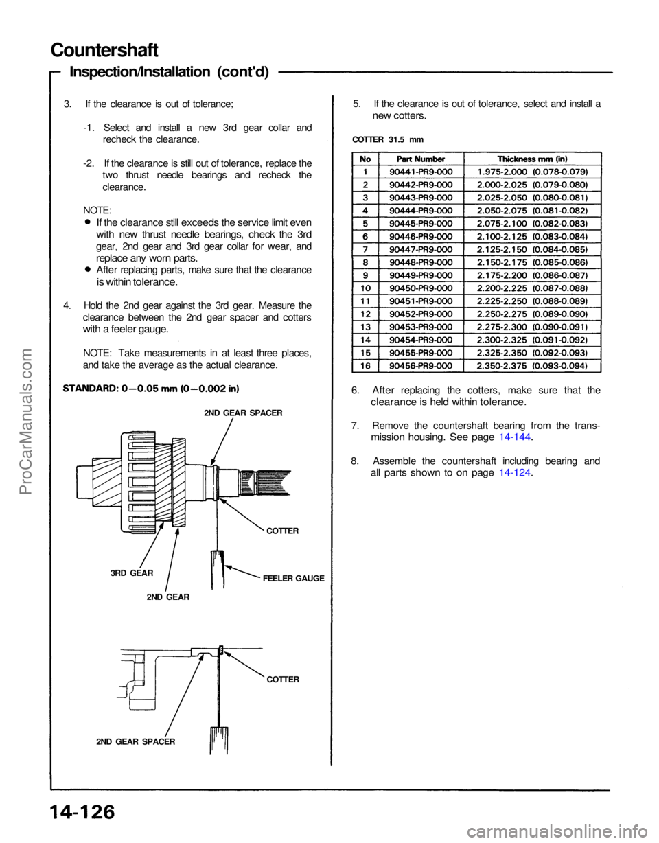
5. If the clearance is out of tolerance, select and install a
new cotters.
COTTER 31.5 mm
Countershaft
Inspection/Installation (cont'd)
3. If the clearance is out of tolerance; -1. Select and install a new 3rd gear collar andrecheck the clearance.
-2. If the clearance is still out of tolerance, replace the two thrust needle bearings and recheck the
clearance.
If the clearance still exceeds the service limit even
with new thrust needle bearings, check the 3rd
gear, 2nd gear and 3rd gear collar for wear, and
replace any worn parts.
After replacing parts, make sure that the clearance
is within tolerance.
NOTE:
4. Hold the 2nd gear against the 3rd gear. Measure the clearance between the 2nd gear spacer and cotters
with a feeler gauge.
NOTE: Take measurements in at least three places,
and take the average as the actual clearance.ProCarManuals.com
Page 1273 of 1640
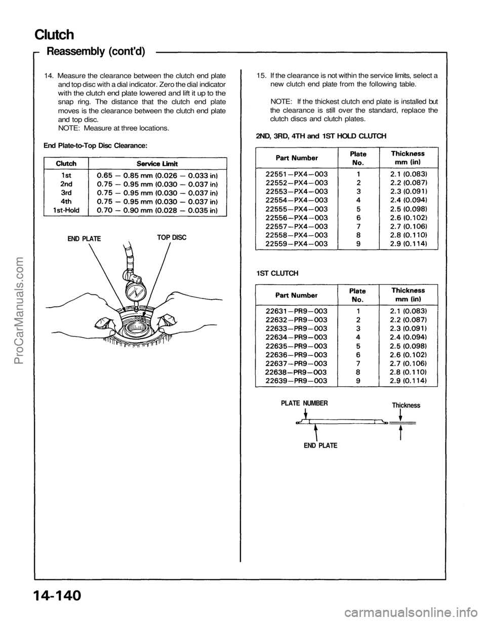
Clutch
Reassembly (cont'd)
14. Measure the clearance between the clutch end plate
and top disc with a dial indicator. Zero the dial indicator
with the clutch end plate lowered and lift it up to the
snap ring. The distance that the clutch end plate
moves is the clearance between the clutch end plate
and top disc.
NOTE: Measure at three locations.
End Plate-to-Top Disc Clearance:
15. If the clearance is not within the service limits, select a
new clutch end plate from the following table.
NOTE: If the thickest clutch end plate is installed but
the clearance is still over the standard, replace the
clutch discs and clutch plates.
2ND, 3RD, 4TH and 1ST HOLD CLUTCH
END PLATE
TOP DISC
1ST CLUTCH
PLATE NUMBER
Thickness
END PLATEProCarManuals.com
Page 1298 of 1640
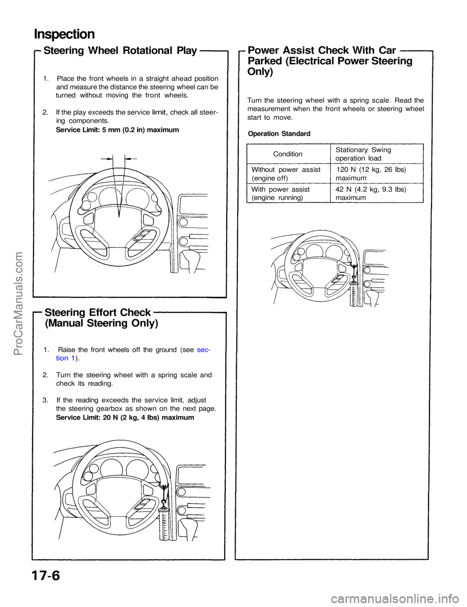
Inspection
Steering Wheel Rotational Play
1. Place the front wheels in a straight ahead position and measure the distance the steering wheel can be
turned without moving the front wheels.
2. If the
play
exceeds
the
service
limit,
check
all
steer- ing components.
Service Limit: 5 mm (0.2 in) maximum
Steering Effort Check (Manual Steering Only)
Operation Standard
Turn the steering wheel with a spring scale. Read the
measurement when the front wheels or steering wheel
start to move.Power Assist Check With Car
Parked (Electrical Power Steering
Only)
1. Raise the front wheels off the ground (see sec-
tion 1).
2. Turn the steering wheel with a spring scale and check its reading.
3. If the reading exceeds the service limit, adjust the steering gearbox as shown on the next page.
Service Limit: 20 N (2 kg, 4 Ibs) maximum Condition
Without power assist (engine off)
With power assist (engine running) Stationary Swing
operation load
120 N (12 kg, 26
Ibs)
maximum
42 N
(4.2
kg, 9.3
Ibs) maximumProCarManuals.com
Page 1301 of 1640
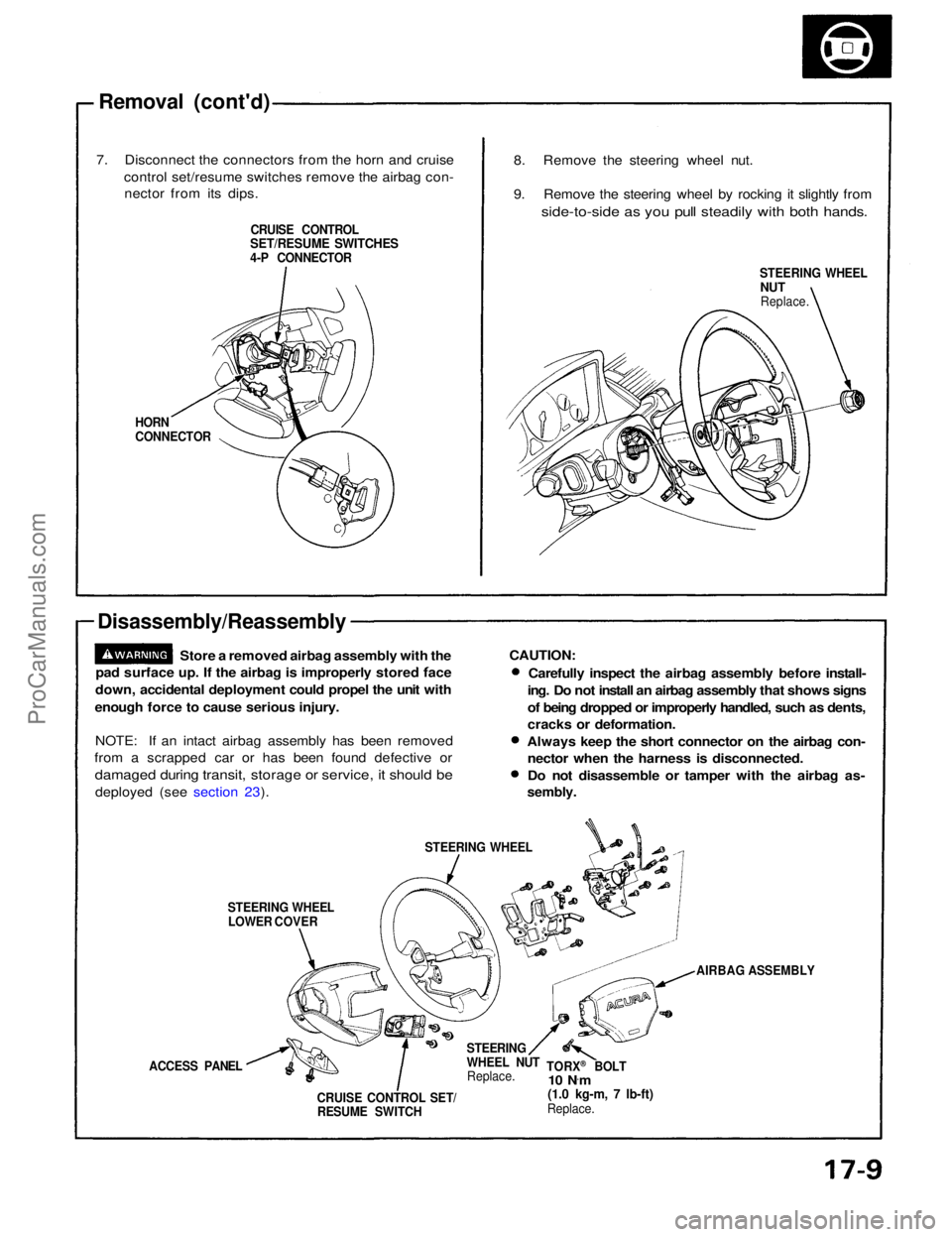
Removal (cont'd)
7. Disconnect the connectors from the horn and cruise control set/resume switches remove the airbag con-nector from its dips.
CRUISE CONTROL
SET/RESUME SWITCHES
4-P CONNECTOR
HORN
CONNECTOR
Disassembly/Reassembly
Store a removed airbag assembly with the
pad surface up. If the airbag is improperly stored face
down, accidental deployment could propel the unit with
enough force to cause serious injury.
NOTE: If an intact airbag assembly has been removed
from a scrapped car or has been found defective or
damaged during transit, storage or service, it should be
deployed (see section 23).
STEERING WHEELLOWER COVER STEERING WHEEL
ACCESS PANEL CRUISE CONTROL SET/RESUME SWITCH STEERING
WHEEL NUT
Replace. TORX
®
BOLT
10 N ·
m
(1.0 kg-m, 7 lb-ft)
Replace. AIRBAG ASSEMBLY
CAUTION:
Carefully inspect the airbag assembly before install-
ing. Do not install an airbag assembly that shows signs
of being dropped or improperly handled, such as dents,
cracks or deformation.
Always keep the short connector on the airbag con- nector when the harness is disconnected.
Do not disassemble or tamper with the airbag as-
sembly.
STEERING WHEEL
NUT
Replace.
8. Remove the steering wheel nut.
9. Remove the steering wheel by rocking it slightly from
side-to-side as you pull steadily with both hands.ProCarManuals.com
Page 1302 of 1640
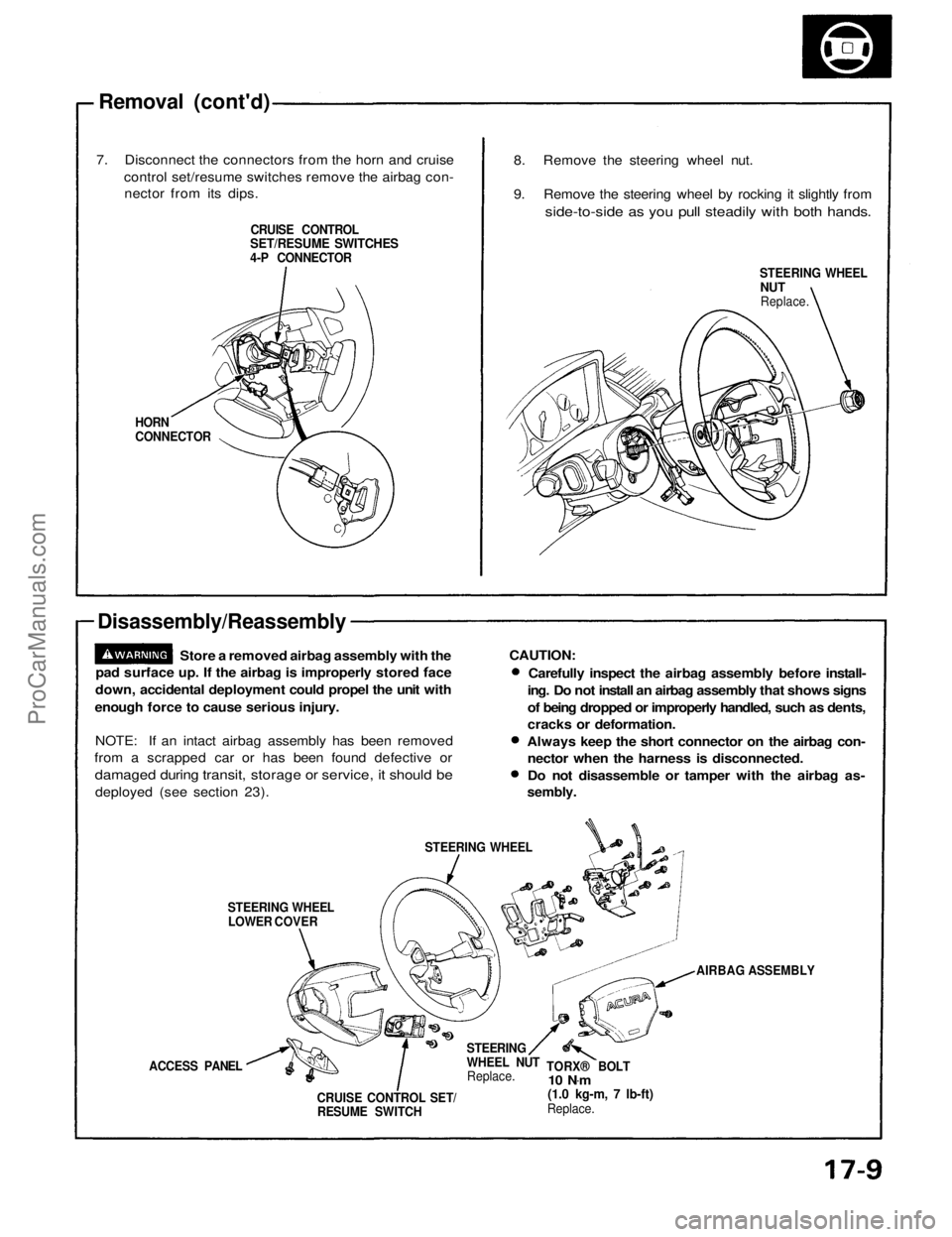
Removal (cont'd)
7. Disconnect the connectors from the horn and cruise control set/resume switches remove the airbag con-nector from its dips.
CRUISE CONTROL
SET/RESUME SWITCHES
4-P CONNECTOR
HORN
CONNECTOR
Disassembly/Reassembly
Store a removed airbag assembly with the
pad surface up. If the airbag is improperly stored face
down, accidental deployment could propel the unit with
enough force to cause serious injury.
NOTE: If an intact airbag assembly has been removed
from a scrapped car or has been found defective or
damaged during transit, storage or service, it should be
deployed (see section 23).
STEERING WHEELLOWER COVER STEERING WHEEL
ACCESS PANEL CRUISE CONTROL SET/RESUME SWITCH STEERING
WHEEL NUT
Replace. TORX® BOLT
10 N .
m
(1.0 kg-m, 7 lb-ft)
Replace. AIRBAG ASSEMBLY
CAUTION:
Carefully inspect the airbag assembly before install-
ing. Do not install an airbag assembly that shows signs
of being dropped or improperly handled, such as dents,
cracks or deformation.
Always keep the short connector on the airbag con- nector when the harness is disconnected.
Do not disassemble or tamper with the airbag as-
sembly.
STEERING WHEEL
NUT
Replace.
8. Remove the steering wheel nut.
9. Remove the steering wheel by rocking it slightly from
side-to-side as you pull steadily with both hands.ProCarManuals.com