Page 753 of 1640

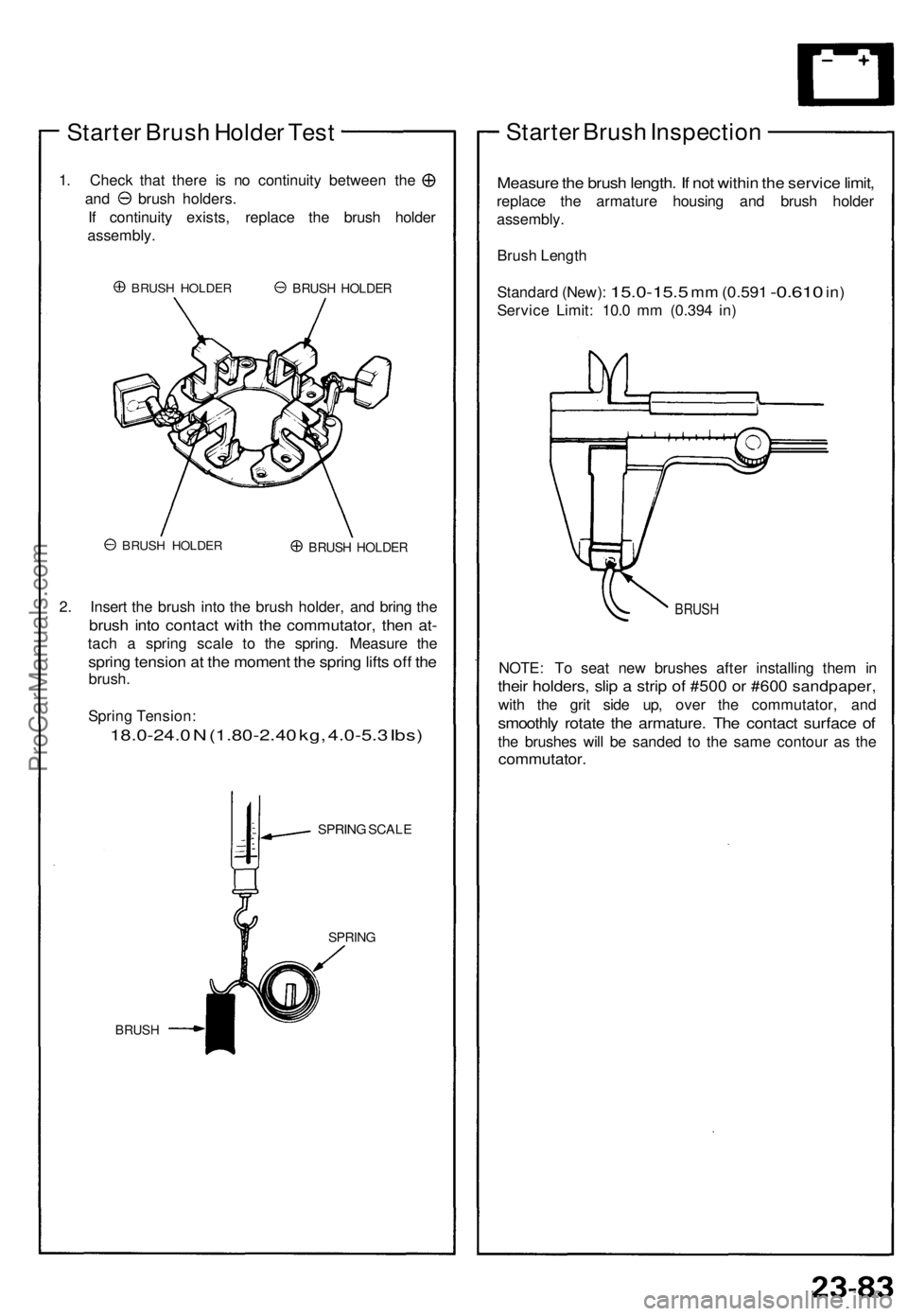
Starter Brush Holder Test
1. Check that there is no continuity between the
and brush holders.
If continuity exists, replace the brush holder
assembly.
BRUSH HOLDER
BRUSH HOLDER
BRUSH HOLDER
2. Insert the brush into the brush holder, and bring the
brush into contact with the commutator, then at-
tach a spring scale to the spring. Measure the
spring tension at the moment the spring lifts off the
brush.
Spring Tension:
18.0-24.0 N (1.80-2.40 kg, 4.0-5.3 Ibs)
SPRING SCALE
BRUSH
SPRING
Starter Brush Inspection
Measure the brush length. If not within the service limit,
replace the armature housing and brush holder
assembly.
Brush Length
Standard (New):
15.0-15.5
mm
(0.591
-0.610
in)
Service Limit: 10.0 mm (0.394 in)
BRUSH
NOTE: To seat new brushes after installing them in
their holders, slip a strip of #500 or #600 sandpaper,
with the grit side up, over the commutator, and
smoothly rotate the armature. The contact surface of
the brushes will be sanded to the same contour as the
commutator.
BRUSH HOLDERProCarManuals.com
Page 754 of 1640

Starting System
Armature Inspection and Test
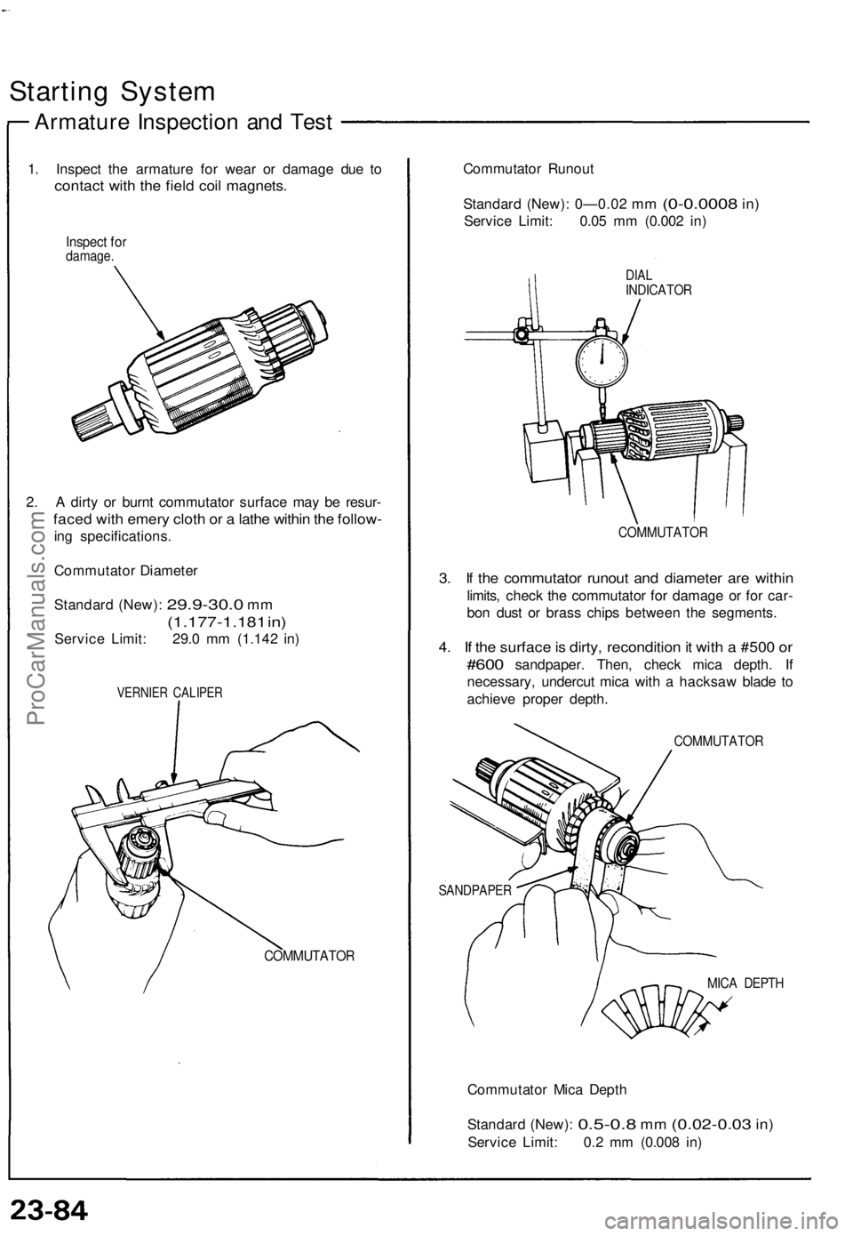
1. Inspect the armature for wear or damage due to
contact with the field coil magnets.
Inspect for
damage.
2. A dirty or burnt commutator surface may be resur-
faced with emery cloth or a lathe within the follow-
ing specifications.
Commutator Diameter
Standard (New):
29.9-30.0
mm
(1.177-1.181 in)
Service Limit: 29.0 mm (1.142 in)
VERNIER CALIPER
COMMUTATOR
Commutator Runout
Standard (New): 0—0.02
mm
(0-0.0008
in)
Service Limit: 0.05 mm (0.002 in)
DIAL
INDICATOR
COMMUTATOR
3. If the commutator runout and diameter are within
limits, check the commutator for damage or for car-
bon dust or brass chips between the segments.
4. If the surface is dirty, recondition it with a #500 or
#600
sandpaper. Then, check mica depth.
If
necessary, undercut mica with a hacksaw blade to
achieve proper depth.
COMMUTATOR
SANDPAPER
MICA DEPTH
Commutator Mica Depth
Standard (New):
0.5-0.8
mm
(0.02-0.03
in)
Service Limit: 0.2 mm (0.008 in)ProCarManuals.com
Page 758 of 1640
Ignition System
Component Local
IGNITION TIMING CONTROL SYSTEM
Description, page 23-89
Inspection, page 23-91 ('94-'96) ('91-'93).
Troubleshooting, section 11
NOISE CONDENSER
Test, page 23-97
SPARK PLUG (6)
Inspection, page 23-96
TEST TACHOMETER CONNECTOR
SERVICE CHECK
CONNECTOR (2-P)
(Connector color: BLU)
CRANKSHAFT POSITION/CYLINDER POSITION
(CKP/CYP) SENSOR
Troubleshooting, section 11
Replacement, section 5
IGNITION COIL (6)
Removal, page 23 94
('94-'96) ('91-'93) Test, page 23-95.
('94-'96) ('91-'93)
IGNITION CONTROL MODULE (ICM)
Replacement, page 23-92
Input Test, page 23-93
Troubleshooting, section 11
SERVICE LOOP
ProCarManuals.com
Page 760 of 1640

Ignition Timin g Inspectio n
SRS component s ar e locate d in thi s area . Revie w th e SR S
componen t locations , precautions , an d procedure s in th e
SR S sectio n 24 befor e performin g repair s o r service .
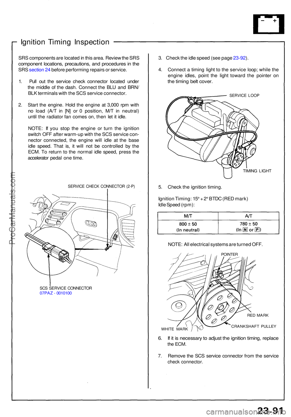
1 . Pul l ou t th e servic e chec k connecto r locate d unde r
th e middl e o f th e dash . Connec t th e BL U an d BRN /
BL K terminal s wit h th e SC S servic e connector .
2 . Star t th e engine . Hol d th e engin e a t 3,00 0 rp m wit h
n o loa d (A/ T i n [N ] o r 0 position , M/ T i n neutral )
unti l th e radiato r fa n come s on , the n le t i t idle .
NOTE : I f yo u sto p th e engin e o r tur n th e ignitio n
switc h OF F afte r warm-u p wit h th e SC S servic e con -
necto r connected , th e engin e wil l idl e a t th e bas e
idl e speed . Tha t is , i t wil l no t b e controlle d b y th e
ECM . T o retur n t o th e norma l idl e speed , pres s th e
accelerato r peda l on e time .
SERVIC E CHEC K CONNECTO R (2-P )
SCS SERVIC E CONNECTO R07PAZ - 001010 0
3. Chec k th e idl e spee d (se e pag e 23-92 ).
4 . Connec t a timin g ligh t t o th e servic e loop ; whil e th e
engin e idles , poin t th e ligh t towar d th e pointe r o n
the timin g bel t cover .
SERVIC E LOO P
TIMIN G LIGH T
5. Chec k th e ignitio n timing .
Ignitio n Timing : 15 ° + 2° BTD C (RE D mark )
Idl e Spee d (rpm) :
NOTE : Al l electrica l system s ar e turne d OFF .
POINTE R
WHITE MAR K
RED MAR K
CRANKSHAF T PULLE Y
6. I f i t i s necessar y to adjus t th e ignitio n timing , replac e
the ECM .
7. Remov e th e SC S servic e connecto r fro m th e servic e
check connector .
ProCarManuals.com
Page 774 of 1640

Rectifier Test
NOTE: The diodes are designed to allow current to
pass in one direction while blocking it in the opposite
direction. Since the alternator rectifier is made up of
eight diodes (four pairs), each diode must be tested for
continuity in both directions with an ohmmeter that has
diode checking capability; a total of sixteen checks.
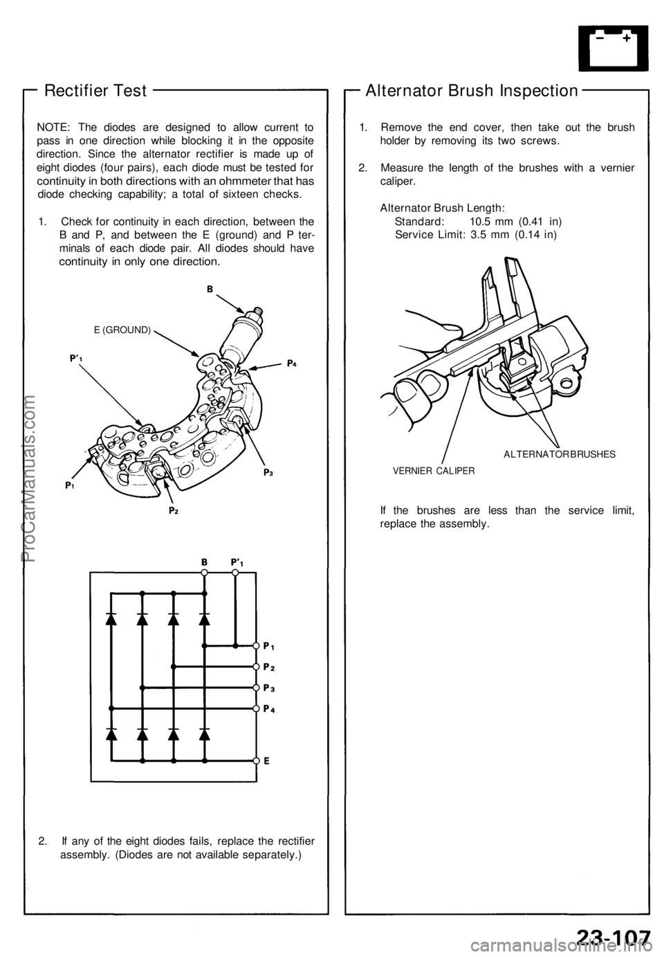
1. Check for continuity in each direction, between the
B and P, and between the E (ground) and P ter-
minals of each diode pair. All diodes should have
continuity in only one direction.
E (GROUND)
2. If any of the eight diodes fails, replace the rectifier
assembly. (Diodes are not available separately.)
Alternator Brush Inspection
1. Remove the end cover, then take out the brush
holder by removing its two screws.
2. Measure the length of the brushes with a vernier
caliper.
Alternator Brush Length:
Standard: 10.5 mm (0.41 in)
Service Limit: 3.5 mm (0.14 in)
ALTERNATOR BRUSHES
VERNIER CALIPER
If the brushes are less than the service limit,
replace the assembly.ProCarManuals.com
Page 786 of 1640
Gauge Assembly
Gauge/Terminal Location Index
SRS components are located in this area. Review the SRS component locations, precautions, and procedures in the SRS
section (24) before performing repairs or service.
SPEEDOMETER:
Indicates 60 mph [60km/h] at 1.026 [637]
rpm of the vehicle speed sensor (VSS).
FUEL GAUGE: Gauge test, page 23-134 Sending Unit Test, page 23-135
VOLTAGE METER:
If, with the No. 5 (15 A) fuse
and other gauges
OK, the pointer of the
voltage meter does not move at all,
replace the voltage
meter.
SAFETY INDICATOR SYSTEM:
See page 23-145 ('93-'96) ('91-'92)A/T GEAR POSITION
INDICATOR SYSTEM:
See page 23-156 ENGINE OIL PRESSURE
GAUGE:
Test page 23-137
ENGINE COOLANT TEMPERATURE (ECT) GAUGE:
Gauge Test, page 23-136 Sender Test, page 23-136
TACHOMETER:
Indicates 100 rpm at 300 pulses per minute
of the igniter unit.ProCarManuals.com
Page 787 of 1640
Gauge Assembl y
Removal
SRS component s ar e locate d in thi s area . Revie w th e SR S
componen t locations , precautions , an d procedure s i n th e
SR S sectio n 24 befor e performin g repair s o r service .
1 . Remov e th e dashboar d lowe r cover , an d disconnec t
th e floo r wir e harnes s connectors .
2 . Remov e th e tw o screws , the n remov e th e dashboar d
lowe r pa d fro m th e dashboard .
DASHBOAR DLOWER
COVE R
DASHBOAR DLOWER PA D
3. Remov e the thre e screws , then remov e the tilt cove r
fro m th e steerin g column .
TILT COVE R
4. Disconnec t th e connector s fro m th e instrumen t
pane l switches .
5 . Remov e th e si x screws , the n remov e th e instrumen t
pane l tri m fro m th e dashboard .
INSTRUMEN T PANE L TRI M
ProCarManuals.com
Page 801 of 1640
Interlock System
Component Location Index
SRS components are located in this area. Review the SRS component locations, precautions, and procedures in the SRS
section (24) before performing repairs or service.
TCS CONTROL UNIT
INTERLOCK CONTROL UNIT
Input Test, page 23-142
A/T GEAR POSITION SWITCH
Test, page 23-160
Replacement, page 23-161 ('93-'96)('91-'92)
KEY INTERLOCK SOLENOID
and KEY INTERLOCK SWITCH (In the steering lock assembly)
Test, page 23-143 SHIFT LOCK SOLENOID
Test, page 23-144
Replacement, page 23-144ProCarManuals.com