Page 331 of 1640
2. Inspect for runout.
Standard: 0.02 mm (0.001 in) max.
Service Limit: 0.05 mm (0.002 in)
NOTE: Support the mainshaft at both ends as
shown.
Rotate two complete revolutions.
If the runout exceeds the service limit, replace the
mainshaft with a new one.ProCarManuals.com
Page 342 of 1640
Oil Pump
Clearance Inspection
1. Check the clearance between the transmission
mating surface of the clutch housing and the oil
pump gear.
Standard:
0.3-0.8
mm
(0.012-0.031
in)
Service Limit: 0.9 mm (0.035 in)
2. Check the axial clearance on the pump rotor.
Clutch Housing-to-Rotor Axial clearance
Standard: 0.03—0.1 mm
(0.001 - 0.004 in)
Service Limit: 0.15 mm (0.006 in)
3. Check the radial clearance on the pump rotor.
Inner Rotor-to-Outer Rotor Radial clearance
Standard: 0.14 mm (0.006 in) max.
Service Limit: 0.2 mm (0.008 in)
4. Check the radial clearance between the clutch
housing and the outer rotor.
Clutch housing-to-Rotor Radial Clearance
Standard: 0.1 - 0.2 mm
(0.004-0.008
in)
Service Limit: 0.22 mm (0.009 in)ProCarManuals.com
Page 373 of 1640

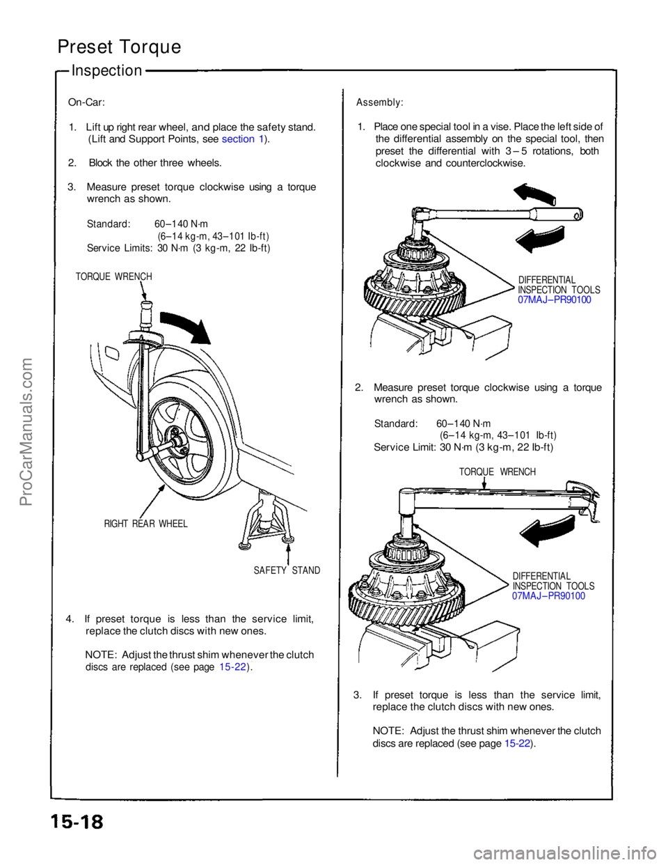
Preset Torque
Inspection
On-Car:
1. Lift up right rear wheel,
and place the safety stand.
(Lift and Support Points, see section 1).
2. Block the other three wheels.
3. Measure preset torque clockwise using a torque wrench as shown.
Standard:
60–140 N·m
(6–14 kg-m, 43–101 Ib-ft)
Service Limits: 30 N·m (3 kg-m, 22 Ib-ft)
TORQUE WRENCH
RIGHT REAR WHEEL SAFETY STAND
4. If preset torque is less than the service limit, replace the clutch discs with new ones.
NOTE: Adjust the thrust shim whenever the clutch
discs are replaced (see page 15-22).
Assembly:
1. Place one special tool in a vise. Place the left side of the differential assembly on the special tool, then
preset the differential with 3 – 5 rotations, both
clockwise and counterclockwise.
DIFFERENTIAL
INSPECTION TOOLS
07MAJ– PR90100
2. Measure preset torque clockwise using a torque wrench as shown.
Standard: 60–140 N·m
(6–14 kg-m, 43–101 Ib-ft)
Service Limit: 30 N·m (3 kg-m, 22 Ib-ft)
TORQUE WRENCH
DIFFERENTIAL
INSPECTION TOOLS
07MAJ – PR90100
3. If preset torque is less than the service limit, replace the clutch discs with new ones.
NOTE: Adjust the thrust shim whenever the clutch
discs are replaced (see page 15-22).
ProCarManuals.com
Page 403 of 1640
Component Location s
Index
NOTE :
• I f a n intac t airba g assembl y ha s bee n remove d fro m a scrappe d ca r o r ha s bee n foun d defectiv e o r damage d durin g transit ,
storag e o r service , i t shoul d b e deploye d (se e sectio n 24 ).
• Befor e removin g th e gearbox , remov e th e ignitio n ke y t o loc k th e steerin g shaft .
• Afte r installin g th e gearbox , chec k th e whee l alignmen t an d adjus t i f necessary .
EPS CONTRO L UNI TReplacement , pag e 17-6 4
STEERIN G GEARBO XRemoval/Installation , pag e 17-5 5Illustrate d Index , pag e 17-5 9Pinio n Preloa d Inspection , pag e 17-6 0Rack Guid e Scre w Adjustment , pag e 17-6 0
STEERIN G WHEEL /AIRBAG ASSEMBL YRemoval, pag e 17-4 5Disassembly , pag e 17-4 6Installation , pag e 17-4 7
STEERIN G COLUM NRemoval , pag e 17-4 9Inspection , pag e 17-5 1Installation , pag e 17-5 2
ProCarManuals.com
Page 422 of 1640
Diagnostic Trouble Code (DTC) Indication
Example:
1.3 seconds
DTC Indication Pattern:
DTC:
11
DTC:
12
EPS Indicator light ON
EPS Indicator light OFF
0.28 seconds
Repeat
Connect the SCS Turn the ignition
service connector switch ON (II)
0.36 seconds 1.3 seconds
• The DTC is indicated by a series of long and short blinks. One long blink equals 10 short blinks.
Add the long and short blinks together to determine the DTC.
• The DTCs are repeated sequentially beginning with the lowest number.
4. Remove the SCS service connector.
NOTE: The Malfunction Indicator Lamp (MIL) will stay on after the engine is started if the SCS service connector is
connected.
5. Remove the CLOCK (7.5 A) fuse in the under-hood fuse/relay box for more than 10 seconds to erase the EPS control
unit memory.ProCarManuals.com
Page 428 of 1640

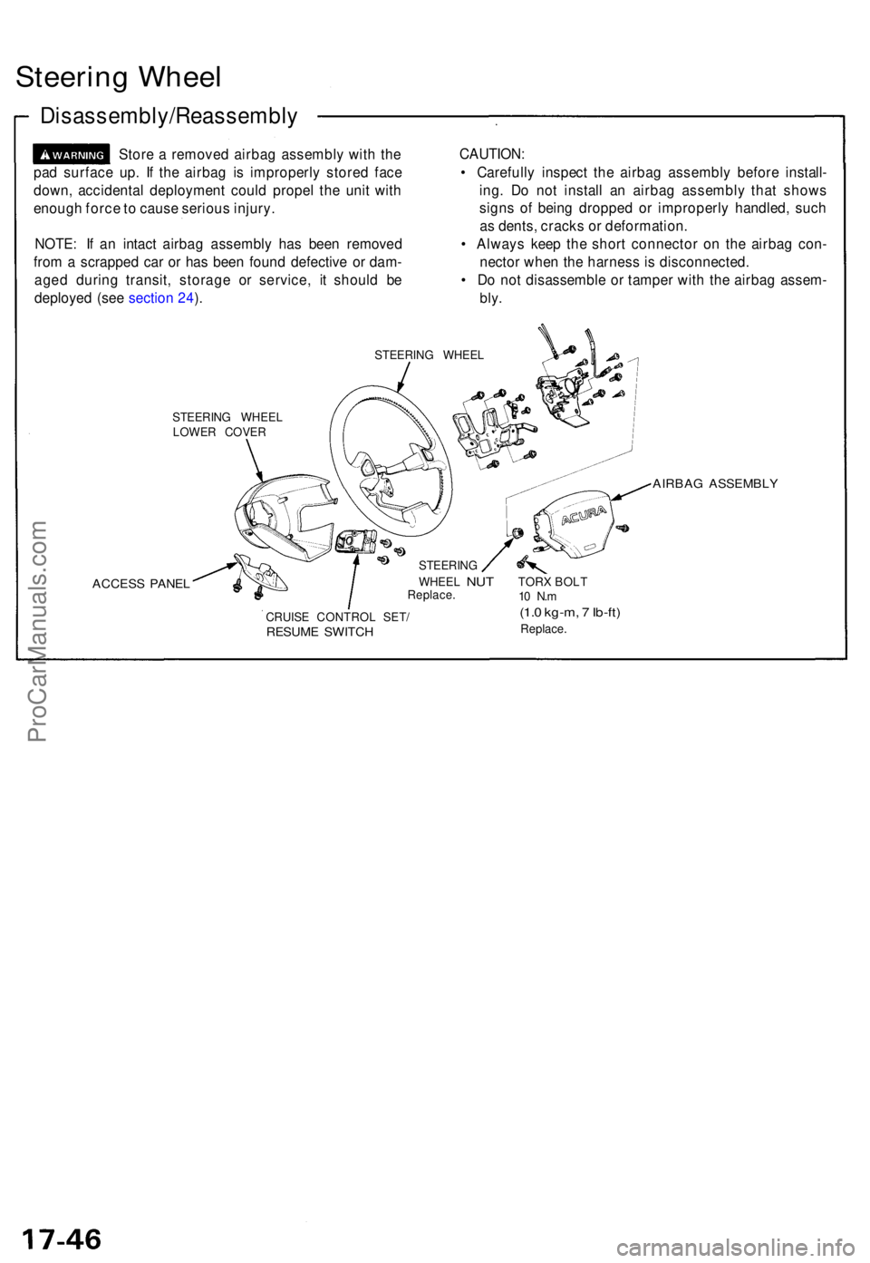
Steering Whee l
Disassembly/Reassembl y
Store a remove d airba g assembl y wit h th e
pa d surfac e up . I f th e airba g i s improperl y store d fac e
down , accidenta l deploymen t coul d prope l th e uni t wit h
enoug h forc e to caus e seriou s injury .
NOTE : I f a n intac t airba g assembl y ha s bee n remove d
fro m a scrappe d ca r o r ha s bee n foun d defectiv e o r dam -
age d durin g transit , storag e o r service , i t shoul d b e
deploye d (se e sectio n 24 ). CAUTION
:
• Carefull y inspec t th e airba g assembl y befor e install -
ing . D o no t instal l a n airba g assembl y tha t show s
sign s o f bein g droppe d o r improperl y handled , suc h
a s dents , crack s o r deformation .
• Alway s kee p th e shor t connecto r o n th e airba g con -
necto r whe n th e harnes s is disconnected .
• D o no t disassembl e o r tampe r wit h th e airba g assem -
bly.
STEERIN G WHEE L
STEERIN G WHEE L
LOWE R COVE R
ACCESS PANE L
AIRBA G ASSEMBL Y
CRUISE CONTRO L SET /RESUM E SWITC H
STEERIN G
WHEE L
NUT TORX BOLTReplace . 10 N .m(1. 0 kg-m , 7 Ib-ft )
Replace .
ProCarManuals.com
Page 498 of 1640

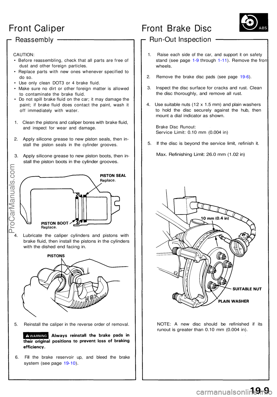
Reassembly
CAUTION:
• Befor e reassembling , chec k tha t al l part s ar e fre e o f
dus t an d othe r foreig n particles .
• Replac e part s wit h ne w one s wheneve r specifie d t o
do so .
• Us e onl y clea n DOT 3 o r 4 brak e fluid .
• Mak e sur e n o dir t o r othe r foreig n matte r i s allowe d
t o contaminat e th e brak e fluid .
• D o no t spil l brak e flui d o n th e car ; i t ma y damag e th e
paint ; i f brak e flui d doe s contac t th e paint , was h i t
of f immediatel y wit h water .
1. Clea n th e piston s an d calipe r bore s wit h brak e fluid ,
and inspec t fo r wea r an d damage .
2. Appl y silicon e greas e t o ne w pisto n seals , the n in -
stal l th e pisto n seal s i n th e cylinde r grooves .
3. Appl y silicon e greas e t o ne w pisto n boots , the n in -
stal l th e pisto n boot s in th e cylinde r grooves .
4. Lubricat e th e calipe r cylinder s an d piston s wit h
brak e fluid , the n instal l th e piston s i n th e cylinder s
with th e dishe d en d facin g in .
5. Reinstal l th e calipe r i n th e revers e orde r o f removal .
6 . Fil l th e brak e reservoi r up , an d blee d th e brak e
system (se e pag e 19-10 ).
NOTE : A ne w dis c shoul d b e refinishe d i f it s
runou t i s greate r tha n 0.1 0 m m (0.00 4 in) .
Fron t Brak e Dis c
Run-Ou t Inspectio n
1. Rais e eac h sid e o f th e car , an d suppor t i t o n safet y
stand (se e pag e 1-9 throug h 1-11 ). Remov e th e fron t
wheels .
2. Remov e th e brak e dis c pad s (se e pag e 19-6 ).
3 . Inspec t th e dis c surfac e fo r crack s an d rust . Clea n
the dis c thoroughly , an d remov e al l rust .
4. Us e suitabl e nut s (1 2 x 1. 5 mm ) an d plai n washer s
to hol d th e dis c securel y agains t th e hub , the n
moun t a dia l indicato r a s shown .
Brake Dis c Runout :
Service Limit : 0.1 0 m m (0.00 4 in )
5. I f th e dis c i s beyon d th e servic e limit , refinis h it .
Max . Refinishin g Limit : 26. 0 m m (1.0 2 in )
Front Caliper
ProCarManuals.com
Page 508 of 1640
Rear Brak e Dis c
Run-Ou t Inspectio n
1. Rais e eac h sid e o f th e car , an d suppor t i t o n safet y
stand s (se e pag e 1- 6 throug h 1-8 ). Remov e th e rea r
wheels .
2 . Remov e th e brak e pad s (se e pag e 19-17 ).
3 . Inspec t th e dis c surfac e fo r grooves , cracks , an d
rust . Clea n th e dis c thoroughl y an d remov e al l rust .
4 . Us e suitabl e nut s (1 2 x 1. 5 mm ) an d plai n washer s
t o hol d th e dis c securel y agains t th e hub , the n
moun t a dia l indicato r a s shown .
Brak e Dis c Runout :
Service Limit : 0.1 0 m m (0.00 4 in )
5. I f th e dis c i s beyon d th e servic e limit , refinis h th e
rotor .
Max . Refinishin g Limit : 19. 0 m m (0.7 5 in )
NOTE : A ne w dis c shoul d b e refinishe d i f it s
runou t i s greate r tha n 0. 1 m m (0.00 4 in) .
ProCarManuals.com