1991 ACURA NSX service
[x] Cancel search: servicePage 39 of 1640
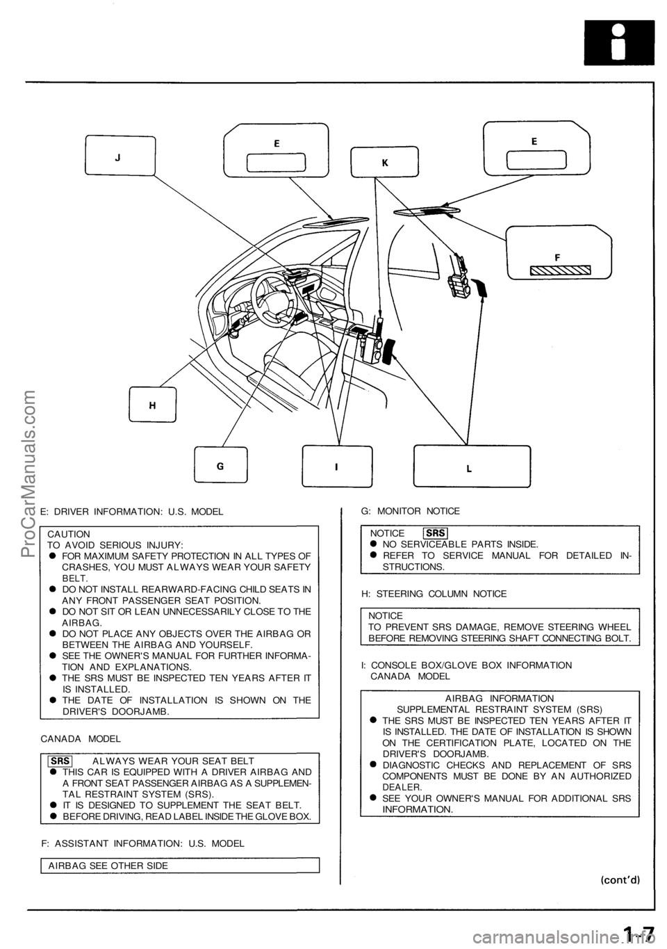
E: DRIVER INFORMATION: U.S. MODEL
CAUTION
TO AVOID SERIOUS INJURY:
FOR MAXIMUM SAFETY PROTECTION IN ALL TYPES OF
CRASHES, YOU MUST ALWAYS WEAR YOUR SAFETY
BELT.
DO NOT INSTALL REARWARD-FACING CHILD SEATS IN
ANY FRONT PASSENGER SEAT POSITION.
DO NOT SIT OR LEAN UNNECESSARILY CLOSE TO THE
AIRBAG.
DO NOT PLACE ANY OBJECTS OVER THE AIRBAG OR
BETWEEN THE AIRBAG AND YOURSELF.
SEE THE OWNER'S MANUAL FOR FURTHER INFORMA-
TION AND EXPLANATIONS.
THE SRS MUST BE INSPECTED TEN YEARS AFTER IT
IS INSTALLED.
THE DATE OF INSTALLATION IS SHOWN ON THE
DRIVER'S DOORJAMB.
CANADA MODEL
ALWAYS WEAR YOUR SEAT BELT
THIS CAR IS EQUIPPED WITH A DRIVER AIRBAG AND
A FRONT SEAT PASSENGER AIRBAG AS A SUPPLEMEN-
TAL RESTRAINT SYSTEM (SRS).
IT IS DESIGNED TO SUPPLEMENT THE SEAT BELT.
BEFORE DRIVING, READ LABEL INSIDE THE GLOVE BOX.
F: ASSISTANT INFORMATION: U.S. MODEL
AIRBAG SEE OTHER SIDE
G: MONITOR NOTICE
NOTICE
NO SERVICEABLE PARTS INSIDE.
REFER TO SERVICE MANUAL FOR DETAILED IN-
STRUCTIONS.
H: STEERING COLUMN NOTICE
NOTICE
TO PREVENT SRS DAMAGE, REMOVE STEERING WHEEL
BEFORE REMOVING STEERING SHAFT CONNECTING BOLT.
I: CONSOLE BOX/GLOVE BOX INFORMATION
CANADA MODEL
AIRBAG INFORMATION
SUPPLEMENTAL RESTRAINT SYSTEM (SRS)
THE SRS MUST BE INSPECTED TEN YEARS AFTER IT
IS INSTALLED. THE DATE OF INSTALLATION IS SHOWN
ON THE CERTIFICATION PLATE, LOCATED ON THE
DRIVER'S DOORJAMB.
DIAGNOSTIC CHECKS AND REPLACEMENT OF SRS
COMPONENTS MUST BE DONE BY AN AUTHORIZED
DEALER.
SEE YOUR OWNER'S MANUAL FOR ADDITIONAL SRS
INFORMATION.ProCarManuals.com
Page 40 of 1640
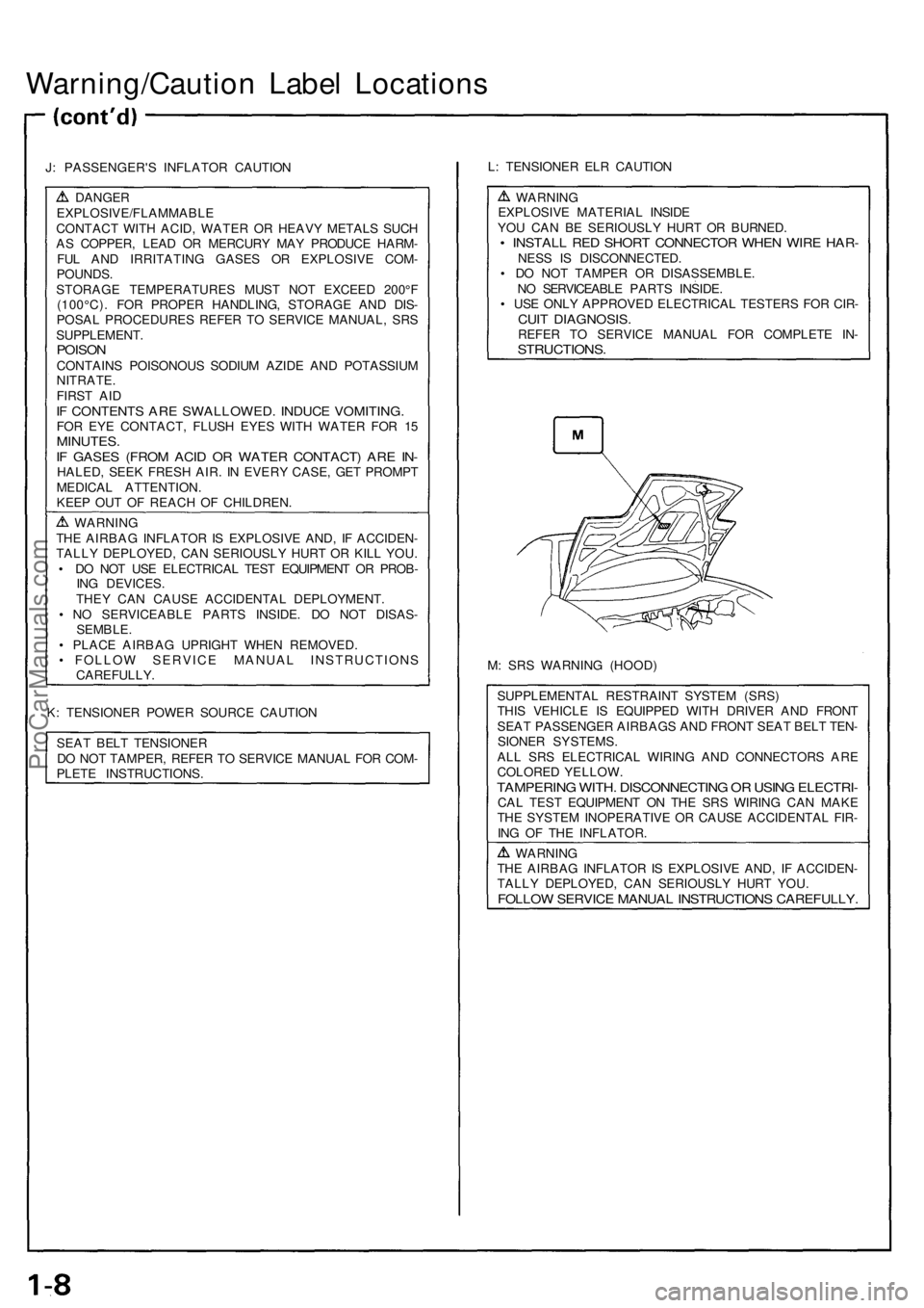
Warning/Caution Labe l Location s
J: PASSENGER' S INFLATO R CAUTIO N
DANGEREXPLOSIVE/FLAMMABL E
CONTAC T WIT H ACID , WATE R O R HEAV Y METAL S SUC H
A S COPPER , LEA D O R MERCUR Y MA Y PRODUC E HARM -
FU L AN D IRRITATIN G GASE S O R EXPLOSIV E COM -
POUNDS .
STORAG E TEMPERATURE S MUS T NO T EXCEE D 200° F
(100°C) . FO R PROPE R HANDLING , STORAG E AN D DIS -
POSA L PROCEDURE S REFE R T O SERVIC E MANUAL , SR S
SUPPLEMENT .
POISONCONTAIN S POISONOU S SODIU M AZID E AN D POTASSIU M
NITRATE .
FIRS T AI D
IF CONTENT S AR E SWALLOWED . INDUC E VOMITING .FOR EY E CONTACT , FLUS H EYE S WIT H WATE R FO R 1 5MINUTES .IF GASE S (FRO M ACI D O R WATE R CONTACT ) AR E IN -HALED , SEE K FRES H AIR . I N EVER Y CASE , GE T PROMP T
MEDICA L ATTENTION .
KEE P OU T O F REAC H O F CHILDREN .
WARNIN G
TH E AIRBA G INFLATO R IS EXPLOSIV E AND , I F ACCIDEN -
TALL Y DEPLOYED , CA N SERIOUSL Y HUR T O R KIL L YOU .
• D O NO T US E ELECTRICA L TES T EQUIPMEN T O R PROB -
IN G DEVICES .
THE Y CA N CAUS E ACCIDENTA L DEPLOYMENT .
• N O SERVICEABL E PART S INSIDE . D O NO T DISAS -
SEMBLE .
• PLAC E AIRBA G UPRIGH T WHE N REMOVED .
• FOLLO W SERVIC E MANUA L INSTRUCTION S
CAREFULLY .
K : TENSIONE R POWE R SOURC E CAUTIO N
SEA T BEL T TENSIONE R
D O NO T TAMPER , REFE R T O SERVIC E MANUA L FO R COM -
PLET E INSTRUCTIONS . L
: TENSIONE R EL R CAUTIO N
WARNIN G
EXPLOSIV E MATERIA L INSID E
YO U CA N B E SERIOUSL Y HUR T O R BURNED .
• INSTAL L RE D SHOR T CONNECTO R WHE N WIR E HAR -NESS I S DISCONNECTED .
• D O NO T TAMPE R O R DISASSEMBLE .
N O SERVICEABL E PART S INSIDE .
• US E ONL Y APPROVE D ELECTRICA L TESTER S FO R CIR -
CUIT DIAGNOSIS .REFER T O SERVIC E MANUA L FO R COMPLET E IN -STRUCTIONS .
M: SR S WARNIN G (HOOD )
SUPPLEMENTA L RESTRAIN T SYSTE M (SRS )
THI S VEHICL E I S EQUIPPE D WIT H DRIVE R AN D FRON T
SEA T PASSENGE R AIRBAG S AN D FRON T SEA T BEL T TEN -
SIONE R SYSTEMS .
AL L SR S ELECTRICA L WIRIN G AN D CONNECTOR S AR E
COLORE D YELLOW .
TAMPERIN G WITH . DISCONNECTIN G O R USIN G ELECTRI -CAL TES T EQUIPMEN T O N TH E SR S WIRIN G CA N MAK E
TH E SYSTE M INOPERATIV E O R CAUS E ACCIDENTA L FIR -
IN G O F TH E INFLATOR .
WARNIN G
TH E AIRBA G INFLATO R IS EXPLOSIV E AND , I F ACCIDEN -
TALL Y DEPLOYED , CA N SERIOUSL Y HUR T YOU .
FOLLO W SERVIC E MANUA L INSTRUCTION S CAREFULLY .
ProCarManuals.com
Page 44 of 1640
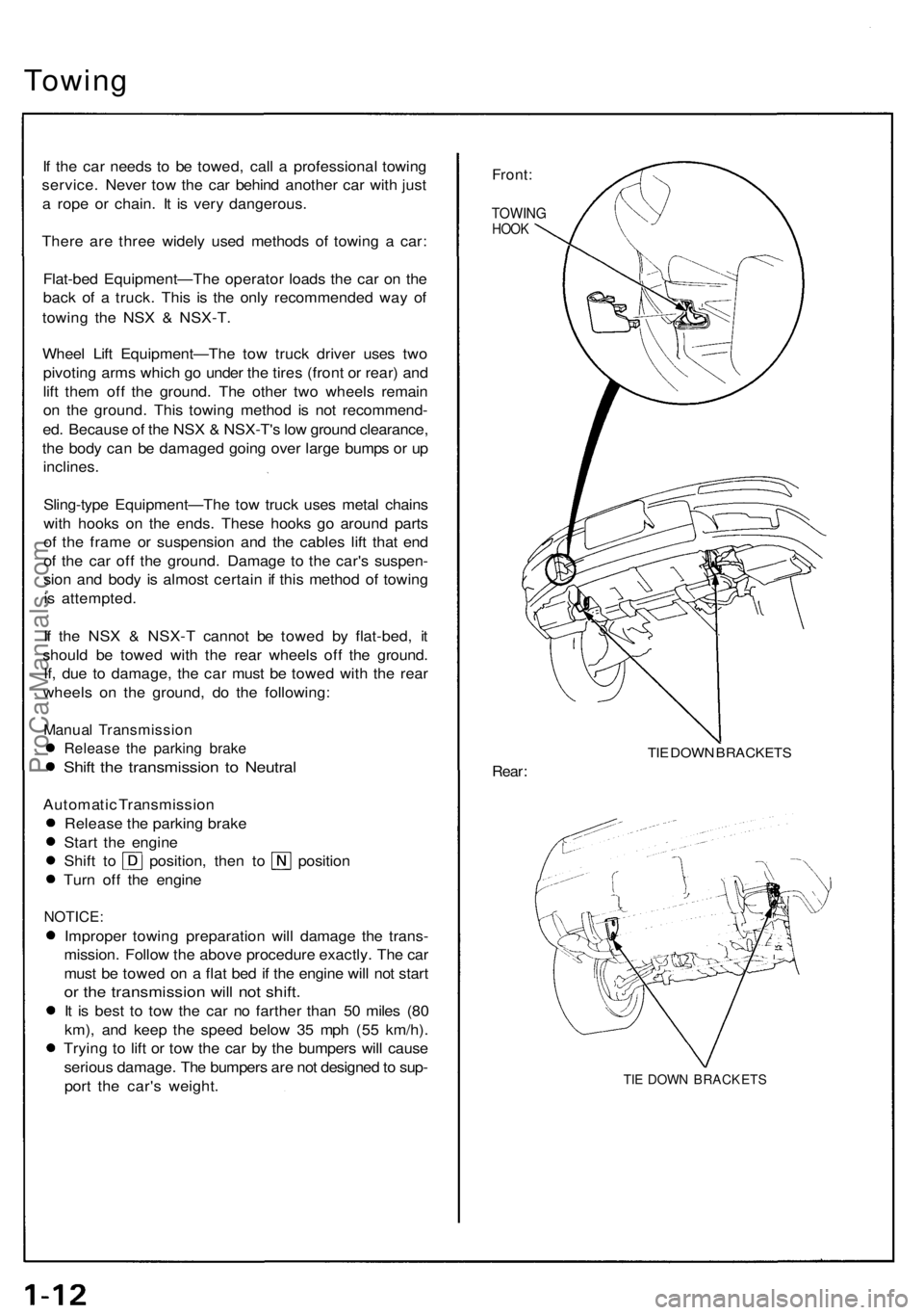
Towing
If th e ca r need s t o b e towed , cal l a professiona l towin g
service . Neve r to w th e ca r behin d anothe r ca r wit h jus t
a rop e o r chain . I t i s ver y dangerous .
Ther e ar e thre e widel y use d method s o f towin g a car :
Flat-be d Equipment—Th e operato r load s th e ca r o n th e
bac k o f a truck . This is th e onl y recommende d wa y o f
towin g th e NS X & NSX-T .
Whee l Lif t Equipment—Th e to w truc k drive r use s tw o
pivotin g arm s whic h g o unde r th e tire s (fron t o r rear ) an d
lif t the m of f th e ground . Th e othe r tw o wheel s remai n
o n th e ground . Thi s towin g metho d i s no t recommend -
ed . Becaus e o f th e NS X & NSX-T' s lo w groun d clearance ,
th e bod y ca n b e damage d goin g ove r larg e bump s o r u p
inclines .
Sling-typ e Equipment—Th e to w truc k use s meta l chain s
wit h hooks on th e ends . Thes e hook s g o aroun d part s
o f th e fram e o r suspensio n an d th e cable s lif t tha t en d
o f th e ca r of f th e ground . Damag e t o th e car' s suspen -
sio n an d bod y i s almos t certai n if thi s metho d o f towin g
i s attempted .
I f th e NS X & NSX- T canno t b e towe d b y flat-bed , i t
shoul d b e towe d wit h th e rea r wheel s of f th e ground .
If , du e t o damage , th e ca r mus t b e towe d wit h th e rea r
wheel s o n th e ground , d o th e following :
Manual Transmissio n
Release th e parkin g brak e
Shift th e transmissio n t o Neutra l
Automati c Transmissio n
Releas e th e parkin g brak e
Star t th e engin e
Shift t o position , the n t o positio n
Tur n of f th e engin e
NOTICE :
Improper towin g preparatio n wil l damag e th e trans -
mission . Follo w th e abov e procedur e exactly . Th e ca r
mus t b e towe d o n a fla t be d if th e engin e wil l no t star t
or th e transmissio n wil l no t shift .
It i s bes t t o to w th e ca r n o farthe r tha n 5 0 mile s (8 0
km) , an d kee p th e spee d belo w 3 5 mp h (5 5 km/h) .
Tryin g t o lif t o r to w th e ca r b y th e bumper s wil l caus e
seriou s damage . Th e bumper s ar e no t designe d to sup -
por t th e car' s weight .
Front:
TOWIN GHOOK
TIE DOW N BRACKET S
Rear:
TIE DOW N BRACKET S
ProCarManuals.com
Page 45 of 1640
Service Precaution s
Handling o f Specia l Nut s an d Bolt s
Becaus e man y section s o n thi s ca r ar e constructe d wit h
aluminu m alloys , us e onl y th e specia l "Dacro " typ e
nut s an d bolt s recommende d b y Acura .
NOTE:
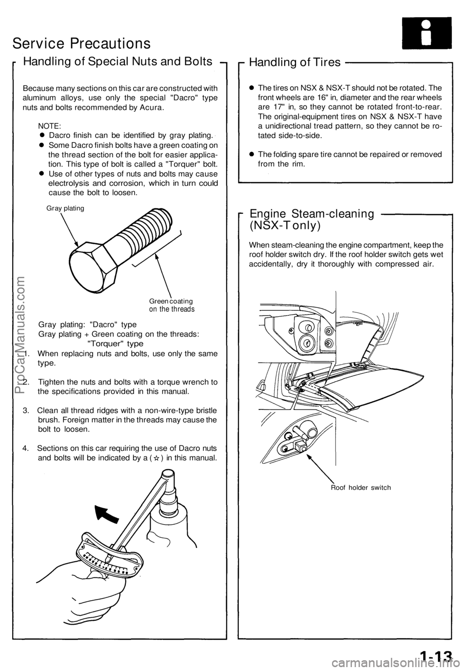
Dacro finis h ca n b e identifie d b y gra y plating .
Som e Dacr o finis h bolt s hav e a gree n coatin g o n
th e threa d sectio n of the bol t fo r easie r applica -
tion . Thi s typ e of bol t i s calle d a "Torquer " bolt .
Us e o f othe r type s of nut s an d bolt s ma y caus e
electrolysi s an d corrosion , whic h in tur n coul d
caus e th e bol t t o loosen .
Gray platin g
Green coatin g
on th e thread s
Gray plating : "Dacro " typ e
Gra y platin g + Gree n coatin g o n th e threads :
"Torquer " typ e
1. Whe n replacin g nut s an d bolts , us e onl y th e sam e
type.
2. Tighte n th e nut s an d bolt s with a torqu e wrenc h t o
th e specification s provide d i n thi s manual .
3 . Clea n al l threa d ridge s wit h a non-wire-typ e bristl e
brush . Foreig n matte r i n th e thread s ma y caus e th e
bol t t o loosen .
4 . Section s o n thi s ca r requirin g th e us e o f Dacr o nut s
and bolt s wil l b e indicate d b y a ( ) in thi s manual .
Handling o f Tire s
The tire s o n NS X & NSX- T shoul d no t b e rotated . Th e
fron t wheel s ar e 16 " in , diamete r an d th e rea r wheel s
ar e 17 " in , s o the y canno t b e rotate d front-to-rear .
Th e original-equipmen t tire s o n NS X & NSX- T hav e
a unidirectiona l trea d pattern , s o the y canno t b e ro -
tate d side-to-side .
Th e foldin g spar e tir e canno t b e repaire d o r remove d
fro m th e rim .
Engin e Steam-cleanin g
(NSX-T only )
When steam-cleanin g th e engin e compartment , kee p th e
roo f holde r switc h dry . I f th e roo f holde r switc h get s we t
accidentally , dr y i t thoroughl y wit h compresse d air .
Roo f holde r switc h
ProCarManuals.com
Page 66 of 1640
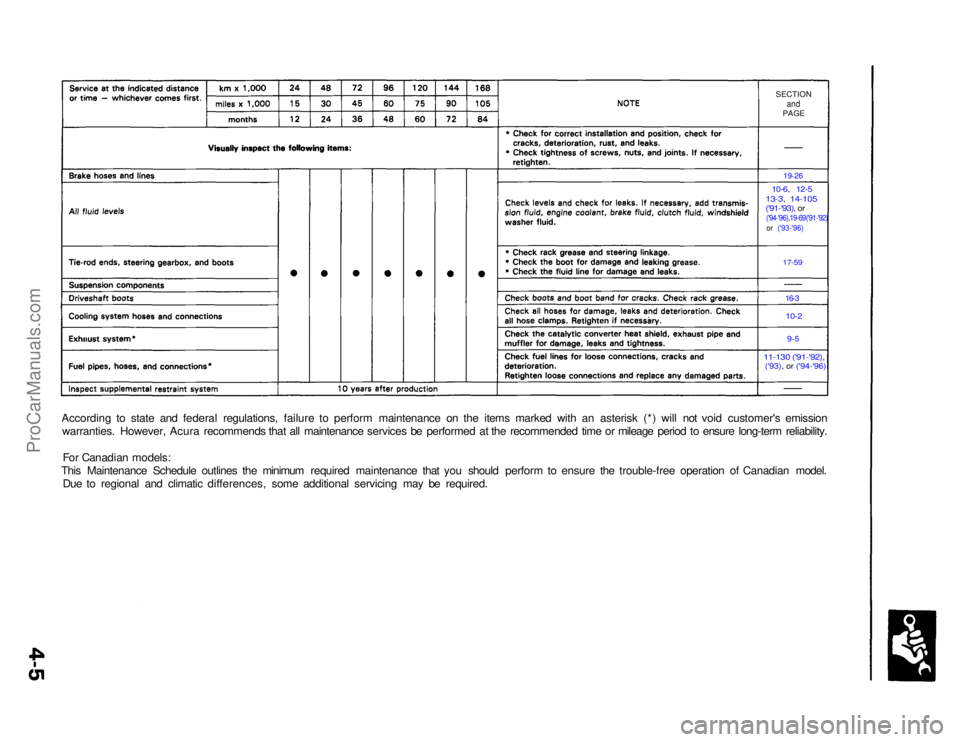
SECTION
and
PAGE
19-26
10-6, 12-5
13-3, 14-105
('91-'93), or('94-'96),19-69('91-'92) or ('93-'96)
17-59
16-3
10-2
9-5
11-130 ('91-'92),('93), or ('94-'96)
According to state and federal regulations, failure to perform maintenance on the items marked with an asterisk (*) will not void customer's emission
warranties. However, Acura recommends that all maintenance services be performed at the recommended time or mileage period to ensure long-term reliability.
For Canadian models:
This Maintenance Schedule outlines the minimum required maintenance that you should perform to ensure the trouble-free operation of Canadian model. Due to regional and climatic differences, some additional servicing may be required.ProCarManuals.com
Page 68 of 1640
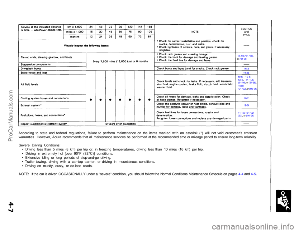
SECTION
and
PAGE
17-59 ('91-'93),
or ('94-'96)
16-3
19-26
10-6, 12-5
13-3, 14-105
('91-'93), or ('94-'96), 19-69
('91-'92),or ('93-'96)
10-2
9-5
11-130 ('91-'92)('93), or ('94-'96)
According to state and federal regulations, failure to perform maintenance on the items marked with an asterisk (*) will not void customer's emission
warranties. However, Acura recommends that all maintenance services be performed at the recommended time or mileage period to ensure long-term reliability.
Severe Driving Conditions: Driving less than 5 miles (8 km) per trip or, in freezing temperatures, driving less than 10 miles (16 km) per trip.
Driving in extremely hot [over 90°F (32°C)] conditions.
Extensive idling or long periods of stop-and-go driving.
Trailer towing, driving with a car-top carrier, or driving in mountainous conditions.
Driving on muddy, dusty, or de-iced roads.
NOTE: If the car is driven OCCASIONALLY under a "severe" condition, you should follow the Normal Conditions Maintenance Schedule on pages 4-4 and 4-5.ProCarManuals.com
Page 72 of 1640
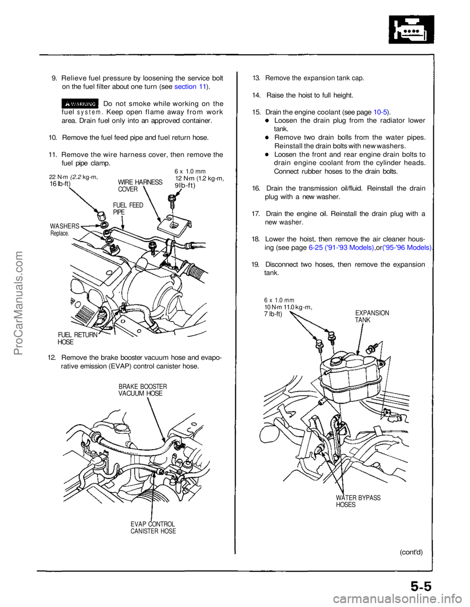
9. Relieve fuel pressure by loosening the service bolt
on the fuel filter about one turn (see section 11).
Do not smoke while working on the
fuel
system.
Keep open flame away from work
area. Drain fuel only into an approved container.
10. Remove the fuel feed pipe and fuel return hose.
11. Remove the wire harness cover, then remove the fuel pipe clamp.
22 N·m
(2.2 kg-m,
16 Ib-ft)
WIRE HARNESS
COVER
6 x 1.0 mm
12 N·m
(1.2 kg-m,
9 lb-ft)
FUEL FEED
PIPE
WASHERS
Replace.
FUEL RETURN
HOSE
12. Remove the brake booster vacuum hose and evapo- rative emission (EVAP) control canister hose.
BRAKE BOOSTER
VACUUM HOSE
EVAP CONTROL
CANISTER HOSE
13. Remove the expansion tank cap.
14. Raise the hoist to full height.
15. Drain the engine coolant (see page
10-5).
Loosen the drain plug from the radiator lower
tank. Remove two drain bolls from the water pipes.
Reinstall the drain bolts with new washers.
Loosen the front and rear engine drain bolts to
drain engine coolant from the cylinder heads.
Connect rubber hoses to the drain bolts.
16. Drain the transmission oil/fluid. Reinstall the drain plug with a new washer.
17. Drain the engine oil. Reinstall the drain plug with a
new washer.
18. Lower the hoist, then remove the air cleaner hous-
ing (see page 6-25 ('91-'93 Mode ls),or('95-'96 Models).
19. Disconnect two hoses, then remove the expansion
tank.
6 x 1.0 mm
10 N·m
11.0 kg-m,
7 lb-ft)
EXPANSION
TANK
WATER BYPASS
HOSES
(cont'd)ProCarManuals.com
Page 100 of 1640
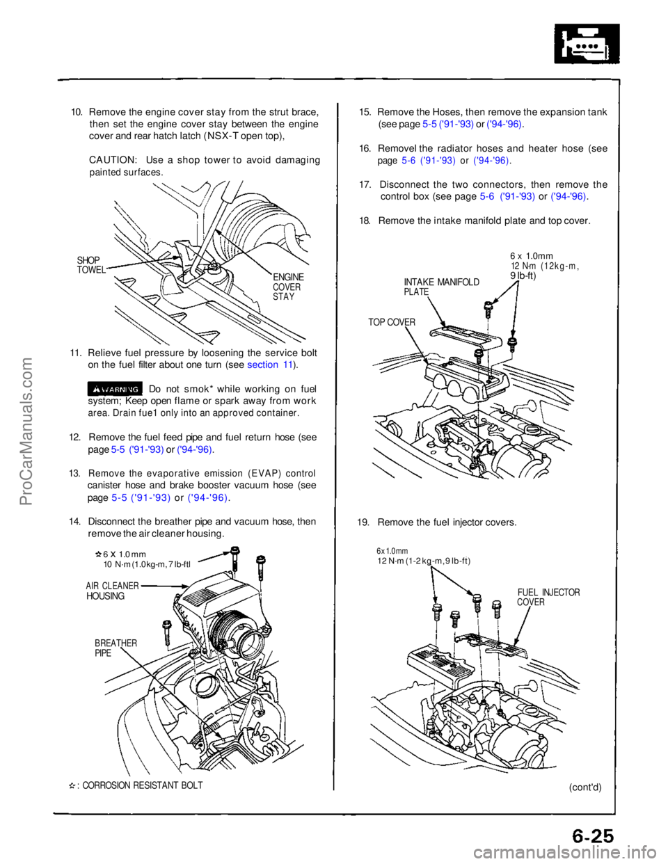
10. Remove the engine cover stay from the strut brace,
then set the engine cover stay between the engine
cover and rear hatch latch (NSX-T open top),
CAUTION: Use a shop tower to avoid damaging
painted surfaces.
SHOP
TOWEL
11. Relieve fuel pressure by loosening the service bolt on the fuel filter about one turn (see section 11).
Do not smok* while working on fuel
system; Keep open flame or spark away from work
area. Drain fue1 only into an approved container.
12. Remove the fuel feed pipe and fuel return hose (see page 5-5 ('91-'93) or ('94-'96).
13. Remove the evaporative emission (EVAP) control
canister hose and brake booster vacuum hose (see
page 5-5 ('91-'93) or ('94-'96).
14. Disconnect the breather pipe and vacuum hose, then remove the air cleaner housing.
6 x 1.0 mm
10 N·m (1.0 kg-m, 7 lb-ftl
AIR CLEANER
HOUSING
BREATHER
PIPE
: CORROSION RESISTANT BOLT
15. Remove the Hoses, then remove the expansion tank
(see page 5-5 ('91-'93) or ('94-'96).
16. Removel the radiator hoses and heater hose (see
page 5-6 ('91-'93) or ('94-'96).
17. Disconnect the two connectors, then remove the
control box (see page 5-6 ('91-'93) or ('94-'96).
18. Remove the intake manifold plate and top cover.
INTAKE MANIFOLD
PLATE
6 x
1.0mm
12 N·m (12kg-m,
9 lb-ft)
TOP COVER
19. Remove the fuel injector covers.
6 x 1.0 mm
12 N·m (1-2 kg-m, 9 lb-ft)
FUEL INJECTOR
COVER
(cont'd)
ENGINE
COVER
STAYProCarManuals.com