Page 110 of 1640
7. If camshaft-to-holder oil clearance is out of
tolerance:
— And camshaft has already been replaced, you
must replace the cylinder head.
— If camshaft has not been replaced, first check to-
tal runout with the camshaft supported on V-
blocks.
Camshaft Total Runout:
Standard (New): 0.03 mm (0.0012 in) max.
Service Limit: 0.04 mm (0.0016 in)
Rotate camshaft
while measuring
— If the total runout of the camshaft is within toler-
ance, replace the cylinder head.
— If the total runout is out of tolerance, replace the
camshaft and recheck. If the oil clearance is still
out of tolerance, replace the cylinder head.
8. Check cam lobe height wear.
Cam Lobe Height Standard (New):
M/T
A/T
Check this area for wear.
Cam position
P: Primary M: Mid S: Secondary
FRONT BANK
REAR BANK
CYLINDER
NUMBER
EXHAUST
INTAKE
CYLINDER
NUMBER
INTAKE
EXHAUSTProCarManuals.com
Page 115 of 1640

Valve Guides
Valve Movement
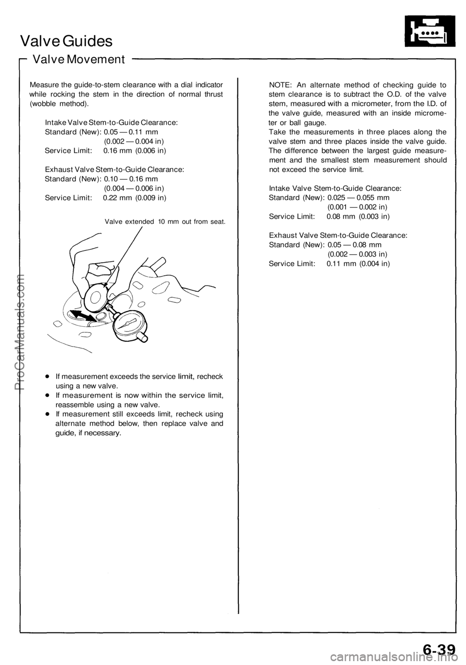
Measure the guide-to-stem clearance with a dial indicator
while rocking the stem in the direction of normal thrust
(wobble method).
Intake Valve Stem-to-Guide Clearance:
Standard (New): 0.05 — 0.11 mm
(0.002 — 0.004 in)
Service Limit: 0.16 mm (0.006 in)
Exhaust Valve Stem-to-Guide Clearance:
Standard (New): 0.10 — 0.16 mm
(0.004 — 0.006 in)
Service Limit: 0.22 mm (0.009 in)
Valve extended 10 mm out from seat.
If
measurement exceeds
the
service
limit,
recheck
using a new valve.
If measurement is now within the service limit,
reassemble using a new valve.
If measurement still exceeds limit, recheck using
alternate method below, then replace valve and
guide, if necessary.
NOTE: An alternate method of checking guide to
stem clearance is to subtract the O.D. of the valve
stem, measured with a micrometer, from the I.D. of
the valve guide, measured with an inside microme-
ter or ball gauge.
Take the measurements in three places along the
valve stem and three places inside the valve guide.
The difference between the largest guide measure-
ment and the smallest stem measurement should
not exceed the service limit.
Intake Valve Stem-to-Guide Clearance:
Standard (New): 0.025 — 0.055 mm
(0.001 — 0.002 in)
Service Limit: 0.08 mm (0.003 in)
Exhaust Valve Stem-to-Guide Clearance:
Standard (New): 0.05 — 0.08 mm
(0.002 — 0.003 in)
Service Limit: 0.11 mm (0.004 in)ProCarManuals.com
Page 153 of 1640
Oil Pump
Removal/lnspection/lnstallation
1. Drain the engine oil. 2. Remove the timing belt (see page 6-15('91-'93)or('94-'96)).
3. Remove the dipstick and the pipe.
4. Remove the oil filter assembly.
5. Remove the oil pan.
6. Remove the oil screen.
7. Remove the baffle plate,
8. Remove the oil pass
pipe and the joint.
9. Remove the mounting bolts and the oil pump
assembly.
Replace.
O-RINGS
Replace.
OIL SCREEN OIL PASS PIPE
AND JOINT
BAFFLE PLATE
OIL PUMP
10. Remove the nine screws from the pump housing,
then separate the housing and cover.
11. Check the inner-to-outer rotor radial clearance.
Inner-to-Outer Rotor Radial Clearance
Standard (New): 0.05 – 0.21 mm (0.002 – 0.008 in)
Service Limit: 0.23 mm (0.009 in)
OUTER ROTOR
INNER ROTOR
12. Check the housing-to-rotor axial clearance. Housing-to-Rotor Axial Clearance
Standard (New): 0.02 – 0.07 mm
(0.001 – 0.003 in)
Service Limit: 0.12 mm (0.005 in)
PUMP HOUSING
OUTER ROTORProCarManuals.com
Page 208 of 1640
II. Engine Control Module (ECM) Reset Procedure
Either of the following actions, will reset the ECM.
• Using the OBD-II scan tool or Honda PGM Tester to clear the ECM's memory.
NOTE: See the OBD-II scan tool or Honda PGM Tester user's manuals for specific operating instructions.
• Turn the ignition switch OFF. Remove the CLOCK (7.5 A) fuse from the under-hood fuse/relay box for 10 seconds.
UNDER-HOOD
FUSE/RELAY BOX
CLOCK
(7.5 A) FUSE
III. Final Procedure (this procedure must be done after any troubleshooting)
1. Remove the SCS Service Connector if it is connected.
NOTE: If the SCS service connector is connected and there are no DTCs stored in the ECM, the MIL will stay on
when the ignition switch is turned on.
2. Do the ECM Reset Procedure.
3. Turn the ignition switch OFF.
4. Disconnect the OBD-II scan tool or Honda PGM Tester from the Data Link Connector,ProCarManuals.com
Page 248 of 1640
6. Disconnect the SCS service connector.
7. Depress the accelerator pedal and stabilize the
engine speed at 1,000 rpm, then slowly release the
pedal until the engine idles, then check the idle
speed.
Idle speed should be:ProCarManuals.com
Page 290 of 1640
Pressure Plate
Inspection
NOTE: If replacement is required, always replace the
pressure plate, mid plate, and flywheel as a set.
1. Inspect the pressure plate surface for wear, cracks,
and burning.
2. Inspect the fingers of the diaphragm spring for
wear at the release bearing contact area.
3. Inspect for warpage using a straight edge and
feeler gauge.
NOTE: Measure across the pressure plate at three
points.
Standard (New): 0.03 mm (0.001 in) max.
Service Limit: 0.15 mm (0.006 in)
STRAIGHT EDGE
FEELER GAUGE
PRESSURE PLATE
If the warpage is more than the service limit, replace
the pressure plate.
Release Bearing
Inspection
1. Check the release bearing for excessive play by
spinning it by hand.
CAUTION: Do not wash the release bearing in
solvent.
2. Replace the release bearing with a new one if there
is excessive play.
RELEASE
BEARINGProCarManuals.com
Page 291 of 1640
1st and 2nd Clutch Discs
Inspection
1. Inspect the lining of the clutch disc for signs of slip-
ping or oil. Replace it if it is burned black or oil
soaked.
2. Measure the clutch disc thickness.
Standard:
1st
Clutch Disc:
8.3-9.0
mm
(0.33-0.35
in)
2nd
Clutch Disc:
7.6-8.3
mm
(0.30-0.33
in)
Service Limit:
1st Clutch Disc: 5.9 mm (0.23 in)
2nd Clutch Disc: 5.4 mm (0.21 in)
CLUTCH DISC
If the thickness is less than the service limit, replace
the clutch disc.
3. Measure the depth from the lining surface to the
rivets, on both sides.
1st and 2nd Clutch Discs:
Standard: 1.1 mm (0.04 in) min.
Service Limit: 0.2 mm (0.01 in)
CLUTCH DISC
If the rivet depth is less than the service limit, replace
the clutch disc.ProCarManuals.com
Page 292 of 1640

Mid Plate
Inspection
NOTE: If replacement is required, always replace the
pressure plate, mid plate, and flywheel as a set.
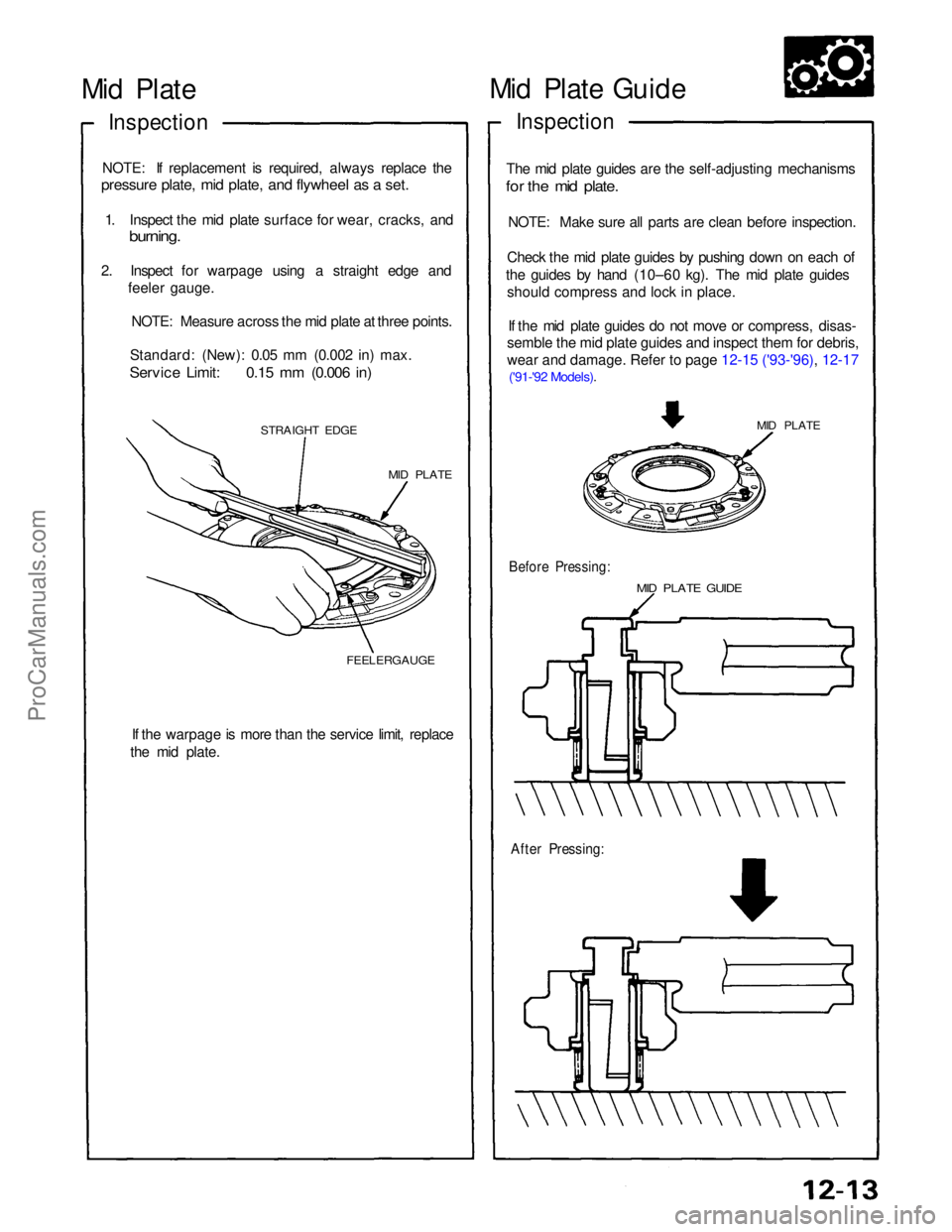
1. Inspect the mid plate surface for wear, cracks, and
burning.
2. Inspect for warpage using a straight edge andfeeler gauge.
NOTE: Measure across the mid plate at three points.
Standard: (New): 0.05 mm (0.002 in) max.
Service Limit: 0.15 mm (0.006 in)
STRAIGHT EDGE
MID PLATE
FEELERGAUGE
If the warpage is more than the service limit, replace
the mid plate.
After Pressing:
MID PLATE GUIDE
Before Pressing:
MID PLATE
The mid plate guides are the self-adjusting mechanisms
for the mid plate.
NOTE: Make sure all parts are clean before inspection.
Check the mid plate guides by pushing down on each of
the guides by hand (10–60 kg). The mid plate guides
should compress and lock in place.
If the mid plate guides do not move or compress, disas-
semble the mid plate guides and inspect them for debris,
wear and damage. Refer to page 12-15
('93-'96), 12-17
('91-'92 Models).
Inspection
Mid Plate GuideProCarManuals.com