Page 515 of 1640
Brake Hoses/Pipe s
Inspection
1. Inspec t th e brak e hose s fo r damage , deterioration , leaks , interferenc e o r twisting .
2 . Chec k th e brak e line s fo r damage , rustin g an d leakage . Als o chec k fo r ben t brak e lines .
3 . Chec k fo r leak s a t hos e an d lin e joint s o r connections , an d retighte n i f necessary .
CAUTION : Replac e th e brak e hos e cli p wheneve r th e brak e hos e i s serviced .
ProCarManuals.com
Page 531 of 1640

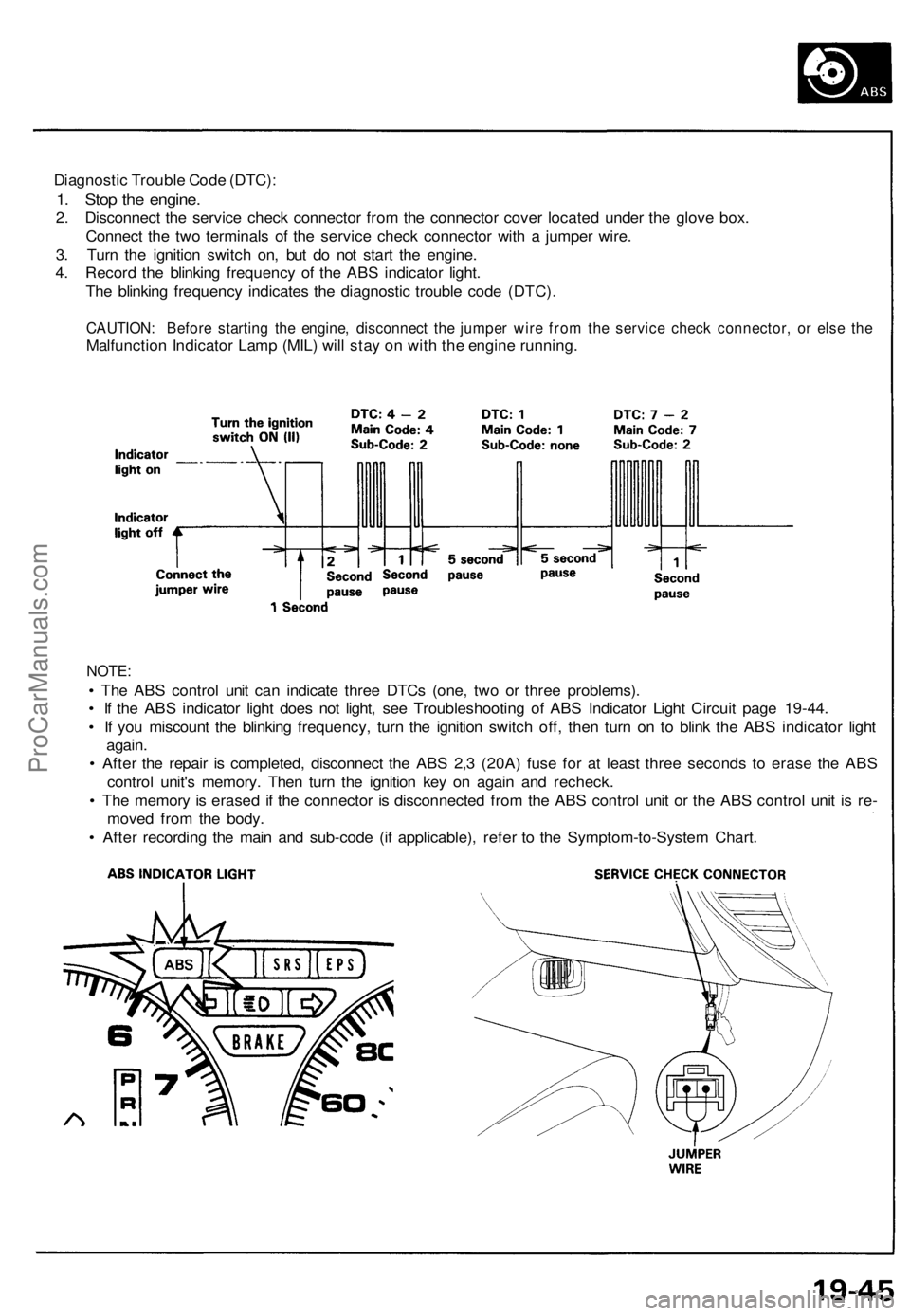
Diagnostic Trouble Code (DTC):
1. Stop the engine.
2. Disconnect the service check connector from the connector cover located under the glove box.
Connect the two terminals of the service check connector with a jumper wire.
3. Turn the ignition switch on, but do not start the engine.
4. Record the blinking frequency of the ABS indicator light.
The blinking frequency indicates the diagnostic trouble code (DTC).
CAUTION: Before starting the engine, disconnect the jumper wire from the service check connector, or else the
Malfunction Indicator Lamp (MIL) will stay on with the engine running.
NOTE:
• The ABS control unit can indicate three DTCs (one, two or three problems).
• If the ABS indicator light does not light, see Troubleshooting of ABS Indicator Light Circuit page 19-44.
• If you miscount the blinking frequency, turn the ignition switch off, then turn on to blink the ABS indicator light
again.
• After the repair is completed, disconnect the ABS 2,3 (20A) fuse for at least three seconds to erase the ABS
control unit's memory. Then turn the ignition key on again and recheck.
• The memory is erased if the connector is disconnected from the ABS control unit or the ABS control unit is re-
moved from the body.
• After recording the main and sub-code (if applicable), refer to the Symptom-to-System Chart.ProCarManuals.com
Page 542 of 1640

ABS Contro l Uni t
Replacemen t
SRS component s ar e locate d in thi s area . Revie w th e SR S
componen t locations , precautions , an d procedure s in th e
SR S
sectio n 2 4 befor e performin g repair s o r service .
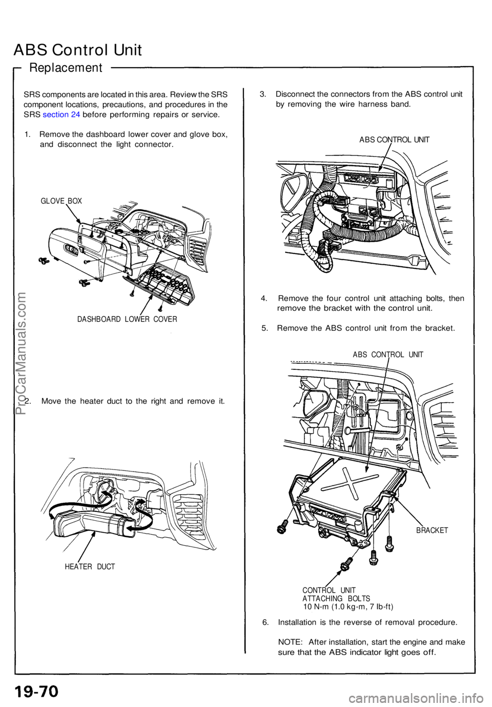
1 . Remov e th e dashboar d lowe r cove r an d glov e box ,
an d disconnec t th e ligh t connector .
GLOVE BO X
DASHBOAR D LOWE R COVE R
2. Mov e th e heate r duc t t o th e righ t an d remov e it .
HEATE R DUC T
3. Disconnec t th e connector s fro m th e AB S contro l uni t
b y removin g th e wir e harnes s band .
ABS CONTRO L UNI T
4. Remov e th e fou r contro l uni t attachin g bolts , the n
remov e th e bracke t wit h th e contro l unit .
5. Remov e th e AB S contro l uni t fro m th e bracket .
ABS CONTRO L UNI T
BRACKE T
CONTRO L UNI T
ATTACHIN G BOLT S
10 N-m (1.0 kg-m, 7 Ib-ft)
6. Installatio n i s th e revers e o f remova l procedure .
NOTE : Afte r installation , star t th e engin e an d mak e
sure tha t th e AB S indicato r ligh t goe s off .
ProCarManuals.com
Page 545 of 1640
Special Tools
Ref.
No.
Tool Number
07PAZ-0010100
Description
SCS Service Connector
Qty
1
19-84('91-'93)('94-'96)Page ReferenceProCarManuals.com
Page 553 of 1640

Troubleshooting
TCS Indicato r Ligh t
Temporar y Drivin g Conditions :
1 . Th e TC S indicato r ligh t wil l com e o n an d th e contro l uni t memorize s th e Diagnosti c Troubl e Cod e (DTC ) unde r certai n
temporar y conditions :
• Th e spar e tir e is installed , o r a tir e o f th e imprope r siz e is installed .
• Th e tir e pressure s ar e no t correct .
2 . I f th e TC S indicato r ligh t doe s no t com e bac k o n afte r correctin g th e tir e o r tir e pressur e problem , th e TC S syste m is
OK .
3. Remov e th e CLOC K (7. 5 A ) fus e fo r a t leas t thre e second s to clea r th e DT C fro m th e TC S contro l uni t memory .
NOTE : Disconnectin g th e CLOC K fus e als o cancel s th e radi o prese t station s an d th e cloc k setting . Mak e not e o f th e
radi o preset s befor e removin g th e fus e s o yo u ca n rese t them .
TC S Diagnosti c Troubl e Cod e (DTC ) Indication :
1 . Sto p th e engine .
2 . Tur n th e ignitio n switc h O N (II) , an d confir m tha t th e TC S indicato r ligh t come s on .
3 . Tur n th e ignitio n switc h off .
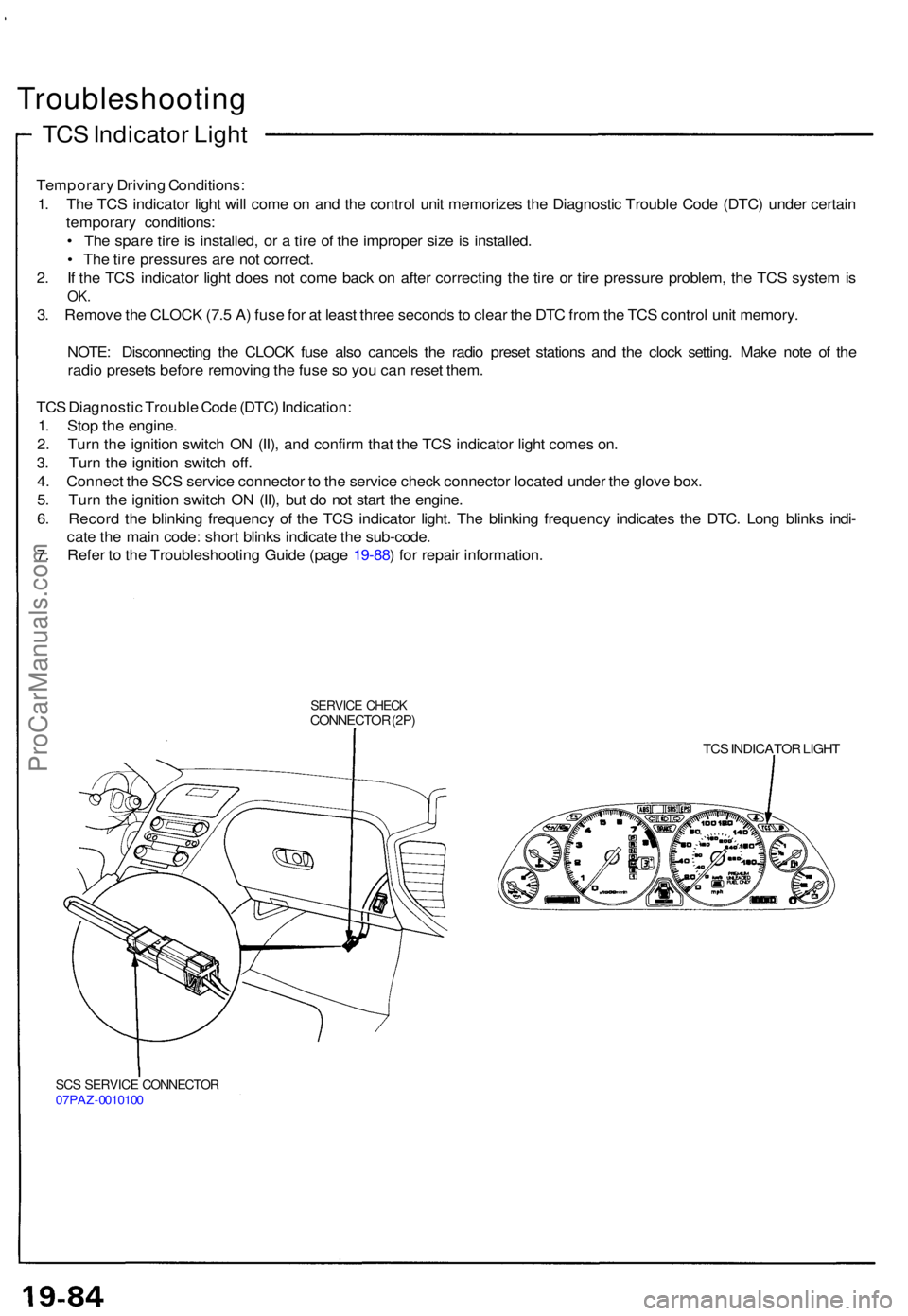
4 . Connec t th e SC S servic e connecto r t o th e servic e chec k connecto r locate d unde r th e glov e box .
5 . Tur n th e ignitio n switc h O N (II) , bu t d o no t star t th e engine .
6 . Recor d th e blinkin g frequenc y o f th e TC S indicato r light . Th e blinkin g frequenc y indicate s th e DTC . Lon g blink s indi -
cat e th e mai n code : shor t blink s indicat e th e sub-code .
7 . Refe r t o th e Troubleshootin g Guid e (pag e 19-88 ) fo r repai r information .
SERVICE CHEC KCONNECTO R (2P )
TCS INDICATO R LIGH T
SCS SERVIC E CONNECTO R07PAZ-001010 0
ProCarManuals.com
Page 560 of 1640
Special Tools
Ref.
No.
Tool Number
07MAZ-SP00200
Description
SRS Service Connector
Qty
2
Page Reference
20-55('91-'93)('94-'96),
56('91-'93)('94-'96),
ProCarManuals.com
Page 578 of 1640
Mirror
Removal Mirror Holder Replacement
1. Insert a Phillips screwdriver in the door mirror through the service hole, then loosen the actuator
retaining screw.
MIRROR
ACTUATORRETAINING SCREW
2. Pull the mirror holder out of the mirror housing. Disconnect the
connector.
ACTUATOR
MIRROR HOLDER
MIRROR HOUSING
3. Remove the actuator (see section 23).
4. Installation is the reverse of the removal procedure.
: CORROSION RESISTANT NUT
4. Installation is the reverse of the removal procedure.
5. Check for water teaks.
NOTE: Do not use high-pressure water.
MOUNTING NUTS
6 x 1.0 mm
10 N·m (1.0 kg-m, 7.2 Ib-ft)
CONNECTOR
(Mirror side)
MIRROR
NOTE: Raise the glass fully.
1. Remove the door panel, and carefully remove the
plastic cover (see pages 20-7('93-'96) ,6('91-'92),
8('93-'96),7('91-'92).
2. Disconnect the connector.
3. Remove the mounting nuts from the hole in the
door while holding the mirror.
NOTE: Do not drop the mounting nuts inside the
door.ProCarManuals.com
Page 604 of 1640
Carpet
Replacement
SRS components are located in this area. Review the SRS component locations, precautions, and procedures in the SRS
section (24) before performing repairs or service.
DASHBOARD
INSIDE SCREW
CARPET
HOOK
(3)
AIR VENT
AM VENT
AIR DUCT
CUPS
FLOOR
CARPET
CONSOLE
CARPET
CONSOLE CARPET
SRS UNIT
SCREW
(cont'd)
1. Remove:
Seats (see page 20-39('93-'96), 38('91-'92)
Footrest
Under-dash fuse box lid (see page 20-38('93-'96),37('91-'92)
Side sill trim (see page 20-38 ('93-'96), 37('91-'92)
Side sill pad (see page 20-38('93-'96), 37('91-'92)
Rear side trim panel (see page 20-38('93-'96), 37('91-'92)
Center armrest (see page 20-49('94-'96)('91-'93)
Center console panel (see page 20-52('94-'96)('91-'93)
2. Detach the clips at The front edge (passenger's).
3. Remove the console carpet attaching screw from the heater unit (passenger's).
4. Disconnect the air duct (driver's) and air vent, then remove the carpet hooks from the dashboard inside screws.ProCarManuals.com