1991 ACURA NSX service
[x] Cancel search: servicePage 609 of 1640
Dashboard
Component Removal/Installation (cont'd)
SRS components are located in this area. Review the SRS component locations, precautions, and procedures in the SRS
section (24) before performing repairs or service.
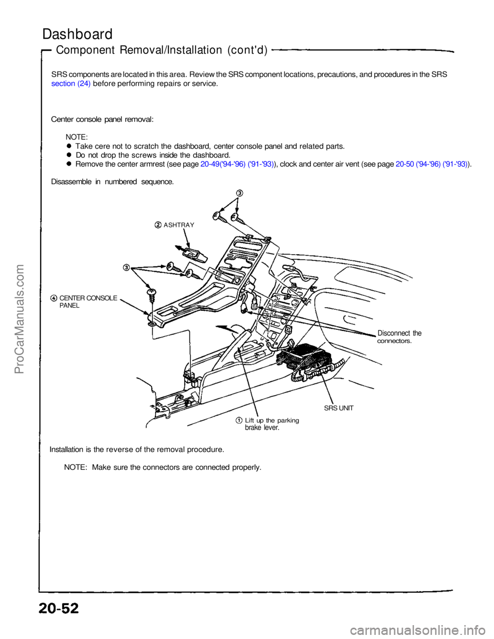
Center console panel removal:
NOTE:
Take cere not to scratch the dashboard, center console panel and related parts.Do not drop the screws inside the dashboard.
Remove the center armrest (see page 20-49('94-'96) ('91-'93)), clock and center air vent (see page 20-50 ('94-'96) ('91-'93)).
Disassemble in numbered sequence.
ASHTRAY
CENTER CONSOLE
PANEL
Disconnect the
connectors.
Lift up the parking
brake lever.
SRS UNIT
Installation is the reverse of the removal procedure. NOTE: Make sure the connectors are connected properly.ProCarManuals.com
Page 611 of 1640
Dashboard
Componen t Removal/Installatio n
SRS component s ar e locate d in thi s area . Revie w th e SR S componen t locations , precautions , an d procedure s in th e SR S
sectio n 24 befor e performin g repair s o r service .
NOTE : Tak e car e no t t o scratc h th e dashboard ,
steerin g colum n an d relate d parts .
CAUTION : Whe n pryin g wit h a fla t ti p screw -
driver , wra p it wit h protectiv e tap e o r a sho p towe l
t o preven t damage .
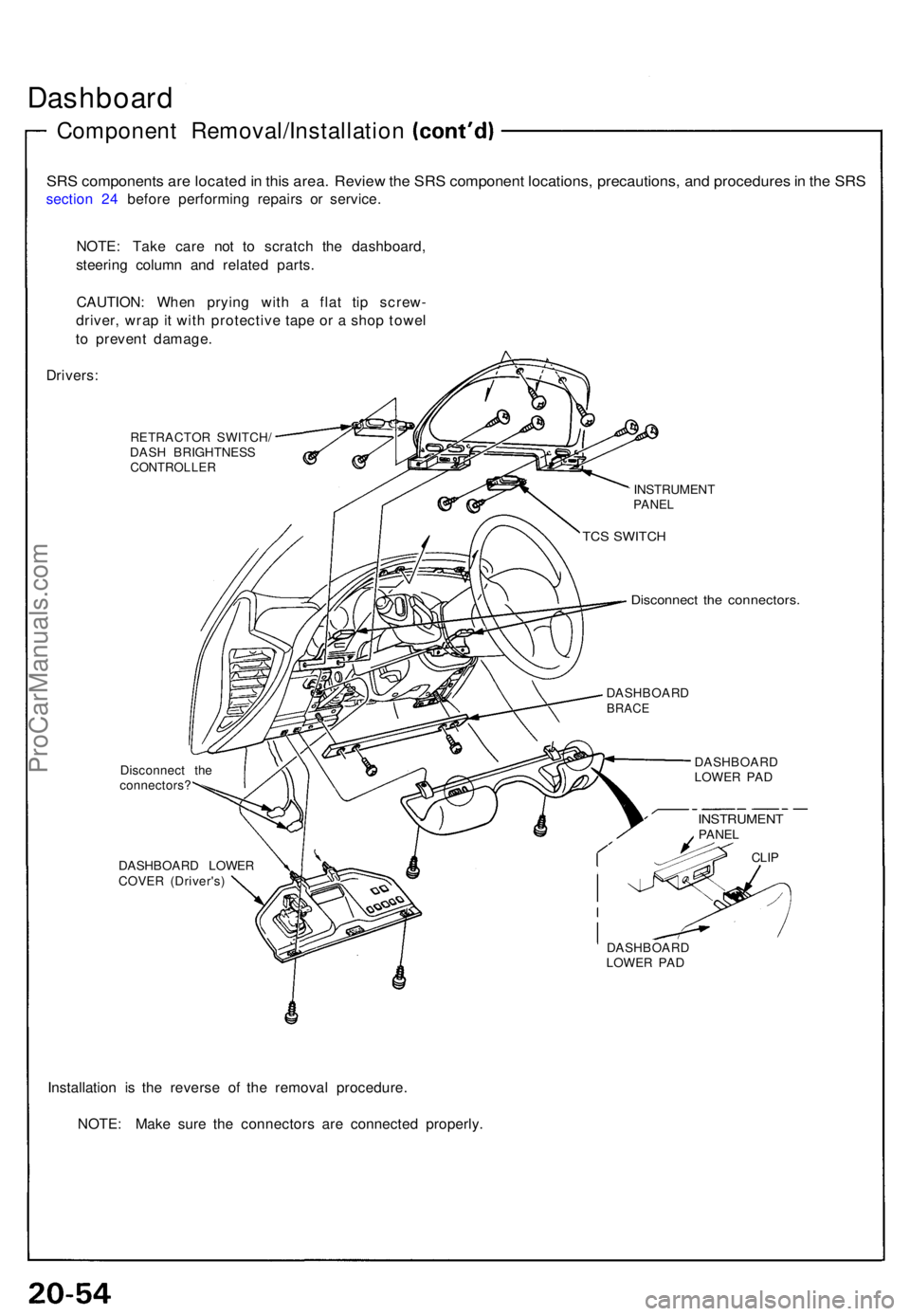
Drivers :
RETRACTO R SWITCH /
DAS H BRIGHTNES S
CONTROLLER
Disconnect th e
connectors ?
DASHBOAR D LOWE R
COVE R (Driver's )
Installation i s th e revers e o f th e remova l procedure .
NOTE : Mak e sur e th e connector s ar e connecte d properly .
Disconnec t th e connectors .
DASHBOAR D
LOWE R PA D
INSTRUMEN
T
PANEL
TCS SWITC H
DASHBOAR DBRACE
DASHBOAR D
LOWE R PA D
INSTRUMEN TPANEL
CLIP
ProCarManuals.com
Page 612 of 1640
Replacement
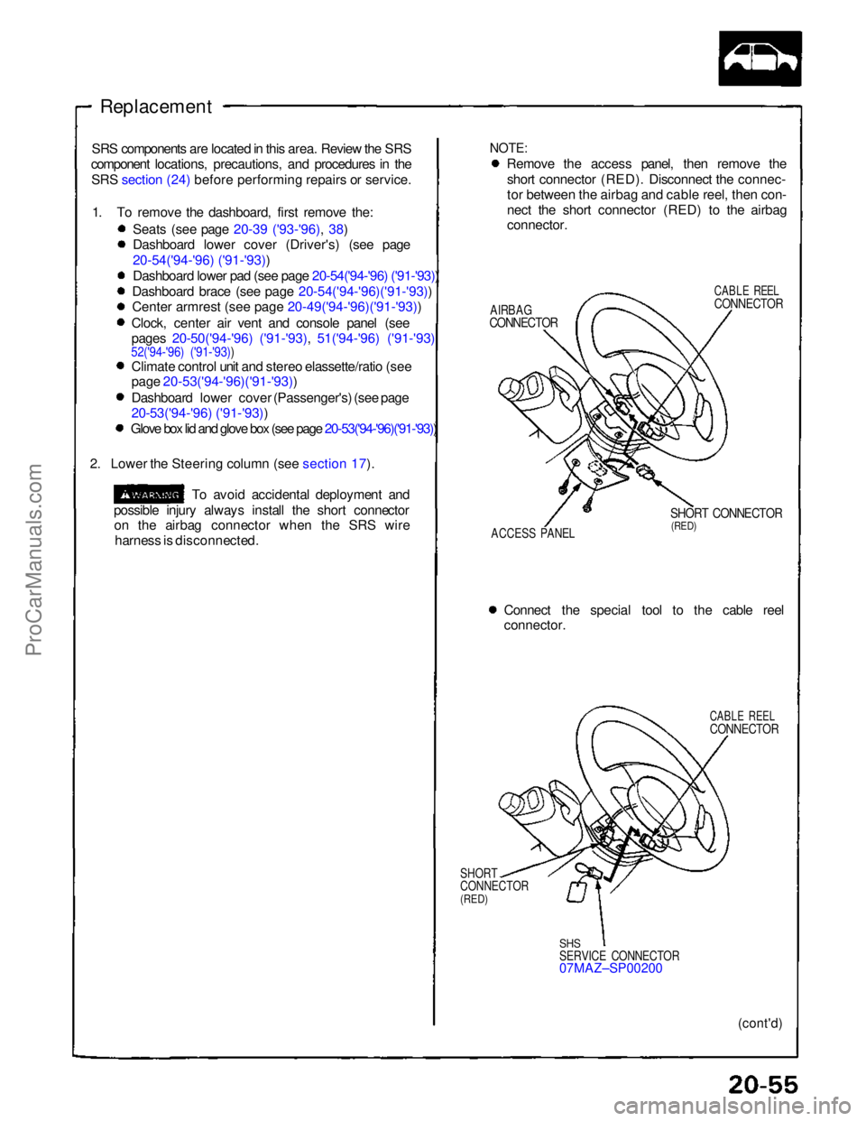
NOTE:
Remove the access panel, then remove the
short connector (RED). Disconnect the connec-
tor between the airbag and cable reel, then con-
nect the short connector (RED) to the airbag
connector.
AIRBAG
CONNECTOR
CABLE REEL
CONNECTOR
ACCESS PANEL
SHORT CONNECTOR
(RED)
Connect the special tool to the cable reel
connector.
CABLE REEL
CONNECTOR
SHORT
CONNECTOR
(RED)
SHS
SERVICE CONNECTOR
07MAZ–SP00200
(cont'd)
SRS components are located in this area. Review the SRS
component locations, precautions, and procedures in the
SRS section (24) before performing repairs or service.
1. To remove the dashboard, first remove the: Seats (see page 20-39 ('93-'96), 38)
Dashboard lower cover (Driver's) (see page
20-54('94-'96) ('91-'93))
Dashboard lower pad (see page 20-54('94-'96) ('91-'93))
Dashboard brace (see page 20-54('94-'96)('91-'93))
Cente
r
armrest (see page 20-49('94-'96)('91-'93))
Clock, center air vent and console panel (see
pages 20-50('94-'96) ('91-'93), 51('94-'96) ('91-'93)
52('94-'96) ('91-'93))
Climate control unit and stereo elassette/ratio (see
page 20-53('94-'96)('91-'93))
Dashboard lower cover (Passenger's) (see page
20-53('94-'96) ('91-'93))
Glove box lid and glove box (see page 20-53('94-'96)('91-'93))
2. Lower the Steering column (see section 17).
To avoid accidental deployment and
possible injury always install the short connector on the airbag connector when the SRS wire
harness is disconnected.ProCarManuals.com
Page 684 of 1640
SRS components are located in this area. Review the SRS component locations, precautions, and procedures in the SRS
section 24 before performing repairs or service.
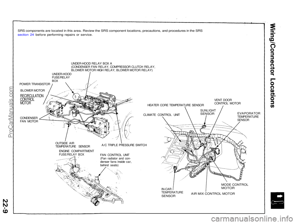
POWER TRANSISTORBLOWER MOTOR
RECIRCULATION
CONTROL
MOTOR
CONDENSER
FAN MOTOR UNDER-HOOD RELAY BOX A
(CONDENSER FAN RELAY, COMPRESSOR CLUTCH RELAY,
BLOWER MOTOR HIGH RELAY, BLOWER MOTOR RELAY)
UNDER-HOOD
FUSE/RELAY
BOX
HEATER CORE TEMPERATURE SENSOR
CLIMATE CONTROL UNIT VENT DOOR
CONTROL MOTOR
OUTSIDE AIR
TEMPERATURE SENSOR ENGINE COMPARTMENT
FUSE/RELAY BOX
A/C TRIPLE PRESSURE SWITCH
FAN CONTROL UNIT (Fan radiator and con-
denser fans inside car,
behind seats)
EVAPORATOR
TEMPERATURE
SENSOR
IN-CAR
TEMPERATURE
SENSOR
MODE CONTROL
MOTOR
AIR MIX CONTROL MOTOR
SUNLIGHT
SENSORProCarManuals.com
Page 689 of 1640
Climate Contro l Uni t
Replacemen t
SRS component s ar e locate d in thi s area . Revie w th e SR S
componen t locations , precautions , an d procedure s in th e
SR S sectio n 24 befor e performin g repair s o r service .
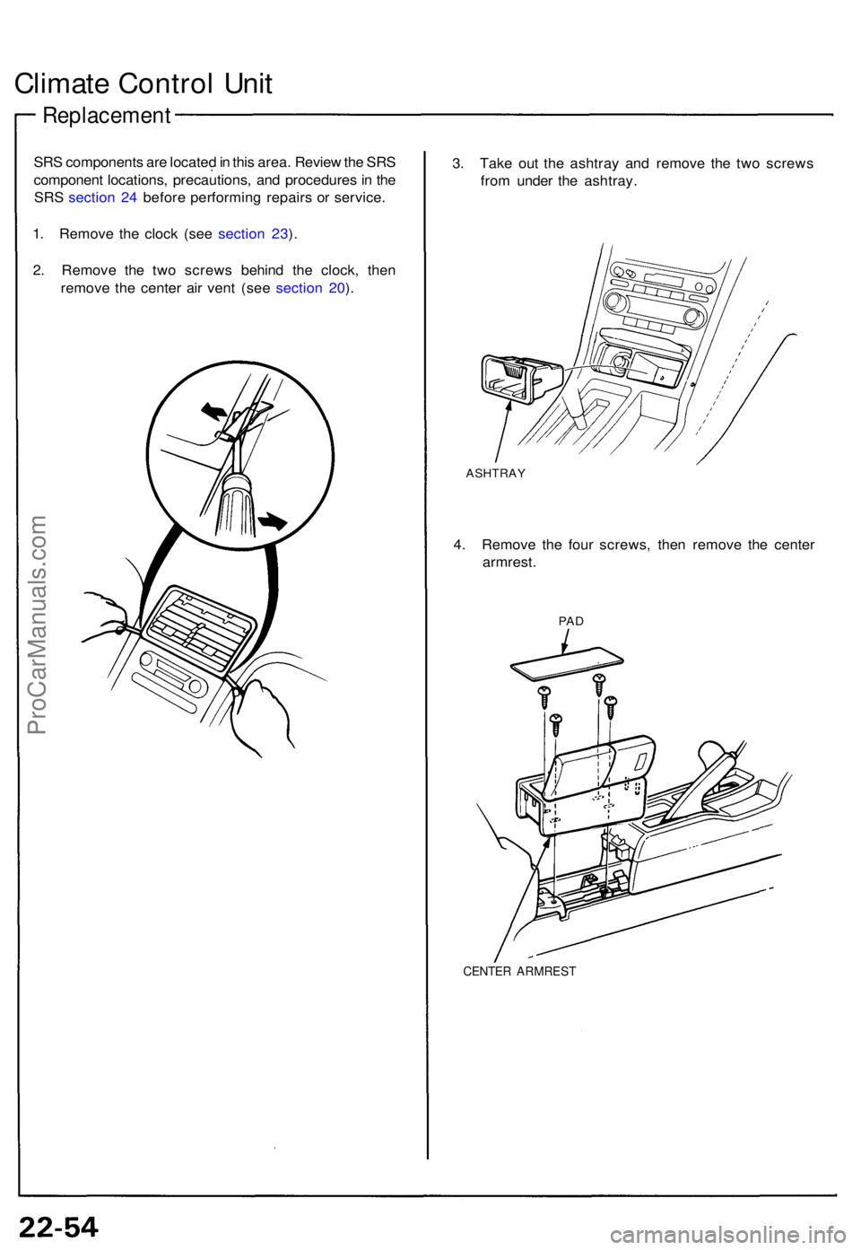
1 . Remov e th e cloc k (se e sectio n 23 ).
2 . Remov e th e tw o screw s behin d th e clock , the n
remov e th e cente r ai r ven t (se e sectio n 20 ). 3
. Tak e ou t th e ashtra y an d remov e th e tw o screw s
fro m unde r th e ashtray .
ASHTRA Y
4. Remov e th e fou r screws , the n remov e th e cente r
armrest .
PAD
CENTE R ARMRES T
ProCarManuals.com
Page 697 of 1640
In-car Temperature Sensor
Removal
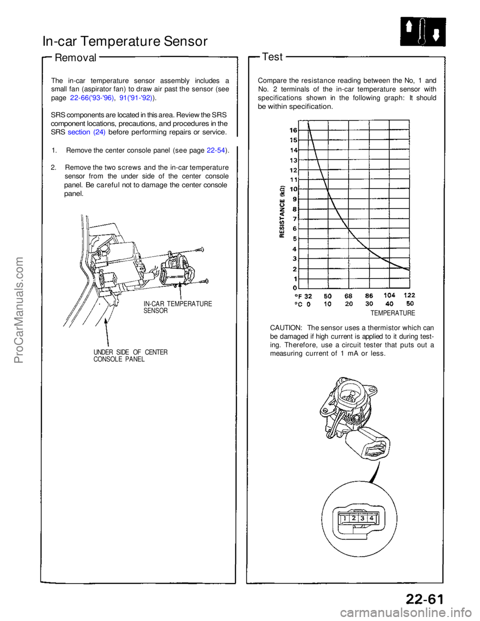
The in-car temperature sensor assembly includes a
small fan (aspirator fan) to draw air past the sensor (see
page 22-66('93-'96), 91('91-'92)).
SRS components are located in this area. Review the SRS
component locations, precautions, and procedures in the
SRS section (24) before performing repairs or service.
1. Remove the center console panel (see page 22-54).
2. Remove the two screws and the in-car temperature sensor from the under side of the center console
panel. Be careful not to damage the center console
panel.
IN-CAR TEMPERATURE
SENSOR
UNDER SIDE OF CENTER
CONSOLE PANEL
Test
Compare the resistance reading between the No, 1 and No. 2 terminals of the in-car temperature sensor with
specifications shown in the following graph: It should
be within specification.
TEMPERATURE
CAUTION: The sensor uses a thermistor which can
be damaged if high current is applied to it during test-
ing. Therefore, use a circuit tester that puts out a
measuring current of 1 mA or less.ProCarManuals.com
Page 705 of 1640
A/C Servic e Tip s an d Precaution s
The ai r conditionin g syste m use s HFC-134 a (R-134a ) refrigeran t an d polyalkyleneglyco l (PAG ) refrigeran t oi l (ND-OI L
8 : P/ N 38899-PR7-A01) , whic h ar e no t compatibl e wit h CFC-1 2 (R-12 ) refrigeran t an d minera l oil . D o no t us e R-1 2 refriger -
an t o r minera l oi l i n thi s system , an d d o no t attemp t t o us e R-1 2 servicin g equipment ; damag e t o th e ai r conditionin g
system o r you r servicin g equipmen t wil l result .
Only us e servic e equipmen t tha t i s U.L.-liste d an d i s certifie d t o mee t th e requirement s o f SA E J221 0 t o remov e R-134a;
fro m th e ai r conditione r system .
CAUTION : Exposur e to ai r conditione r refrigeran t an d lubrican t vapo r o r mis t ca n irritat e eyes , nos e an d throat , Avoi d
breathin g th e ai r conditione r refrigeran t an d lubrican t vapo r o r mist .
I f accidenta l syste m discharg e occurs , ventilat e wor k are a befor e resumin g service .
R-134 a servic e equipmen t o r vehicl e ai r conditione r system s shoul d no t b e pressur e teste d o r lea k teste d wit h compresse d
air.
Som e mixture s o f ai r an d R-134 a hav e bee n show n to b e combustibl e elevate d pressure s an d ca n resul t
i n fir e o r explosio n causin g injur y o r propert y damage . Neve r us e compresse d ai r t o pressur e tes t R-134 a servic e
equipmen t o r vehicl e ai r conditionin g systems .
Additiona l healt h an d safet y informatio n ma y b e obtaine d fro m th e refrigeran t an d lubrican t manufacturers .
1 . Alway s disconnec t th e negativ e cabl e fro m th e batter y wheneve r replacin g ai r conditionin g parts .
2 . Kee p moistur e an d dus t ou t o f th e system . Whe n disconnectin g an y lines , plu g o r cap the fitting s immediately ; don' t
remov e th e cap s o r plug s unti l jus t befor e yo u reconnec t eac h line .
3 . Befor e connectin g an y hos e o r line , appl y a fe w drop s o f refrigeran t oi l (ND-OI L 8 ) t o th e O-ring .
4. Whe n tightenin g o r loosenin g a fitting , us e a secon d wrenc h t o suppor t th e matchin g fitting .
5. Whe n recoverin g th e system , us e a R-134 a refrigeran t Recovery/Recycling/Chargin g System ; don' t releas e
refrigeran t int o th e atmosphere .
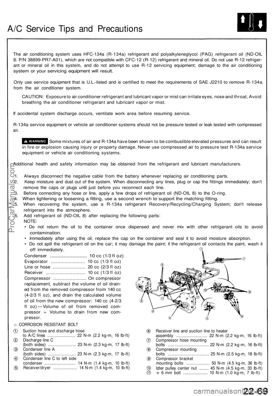
6 . Ad d refrigeran t oi l (ND-OI L 8 ) afte r replacin g th e followin g parts :
NOTE:
• D o no t retur n th e oi l t o th e containe r onc e dispense d an d neve r mi x wit h othe r refrigeran t oil s t o avoi d
contamination .
• Immediatel y afte r usin g th e oil , replac e th e ca p o n th e containe r an d sea l i t t o avoi d moistur e absorption .
• D o no t spil l th e refrigeran t oi l o n th e car ; i t ma y damag e th e paint ; i f th e refrigeran t oi l contact s th e paint , was h i t
of f immediately .
Condenser ........................ . 10 c c (1/ 3 fl oz )
Evaporato r ........................ . 1 0 c c (1/ 3 f l oz )
Lin e o r hos e ....................... . 2 0 c c (2/ 3 f l oz )
Receive r ........................... . 1 0 c c (1/ 3 f l oz )
Compresso r ....................... . O n compresso r
replacement , subtrac t th e volum e o f oi l drain -
e d fro m th e remove d compresso r fro m 14 0 c c
(4-2/ 3 f l oz) , an d drai n th e calculate d volum e
o f oi l fro m th e ne w compressor : 14 0 c c (4-2/ 3
f l oz ) — Volum e o f oi l fro m remove d com -
presso r = Volum e t o drai n fro m ne w com -
pressor .
CORROSIO N RESISTAN T BOL T
Suctio n hos e an d discharg e hos eto A/ C line s ..................... . 2 2 N- m (2. 2 kg-m , 1 6 Ib-ft )Discharg e lin e C(bot h sides ) ..................... . 2 3 N- m (2. 3 kg-m , 1 7 Ib-ft )Condense r lin e A(bot h sides ) ..................... . 2 3 N- m (2. 3 kg-m , 1 7 Ib-ft )Condense r lin e C to lef t sid econdense r ....................... . 1 4 N- m (1. 4 kg-m , 1 0 Ib-ft )Receiver/drye r ................. . 1 4 N- m (1. 4 kg-m , 1 0 Ib-ft )
Receive r lin e an d suctio n lin e t o heate rassembl y ........................ . 2 2 N- m (2. 2 kg-m , 1 6 Ib-ft )Compresso r hos e mountin gbolts .............................. . 2 2 N- m (2. 2 kg-m , 1 6 Ib-ft )Compresso r mountin gbolts .............................. . 2 5 N- m (2. 5 kg-m , 1 8 Ib-ft )Compresso r bracke tmountin g bolt s ................ . 5 0 N- m (4. 5 kg-m , 3 6 Ib-ft )Idler pulle y cente r nu t ....... . 4 5 N- m (4. 5 kg-m , 3 3 Ib-ft )6 m m bol t ................... . 1 0 N- m (1. 0 kg-m , 7 Ib-ft )
ProCarManuals.com
Page 706 of 1640
A/C Syste m Servic e
Performanc e Tes t
The performanc e tes t wil l hel p determin e i f th e ai r con -
ditionin g syste m is operatin g withi n specifications .
Only us e servic e equipmen t tha t i s U.L.-liste d an d is cer -
tifie d t o mee t th e requirement s o f SA E J221 0 t o remov e
HFC-134 a (R-134a ) fro m th e ai r conditionin g system .
CAUTION : Exposur e t o ai r conditione r refrigeran t
an d lubrican t vapo r o r mis t ca n irritat e eyes , nos e
an d throat . Avoi d breathin g th e ai r conditione r
refrigeran t an d lubrican t vapo r o r mist .
I f accidenta l syste m discharg e occurs , ventilat e wor k
are a befor e resumin g service .
R-134 a servic e equipmen t o r vehicl e ai r conditionin g sys -
te m shoul d no t b e pressur e teste d o r lea k teste d wit h
compresse d air .
Som e mixture s o f ai r an d R-134 a hav e
bee n show n to b e combustibl e a t elevate d pressure s
an d ca n resul t i n fir e o r explosio n causin g injur y o r
propert y damage . Neve r us e compresse d ai r t o pres -
sure tes t R-134 a servic e equipmen t o r vehicl e ai r
conditionin g systems .
Additiona l healt h an d safet y informatio n ma y b e obtaine d
fro m th e refrigeran t an d lubrican t manufacturers .
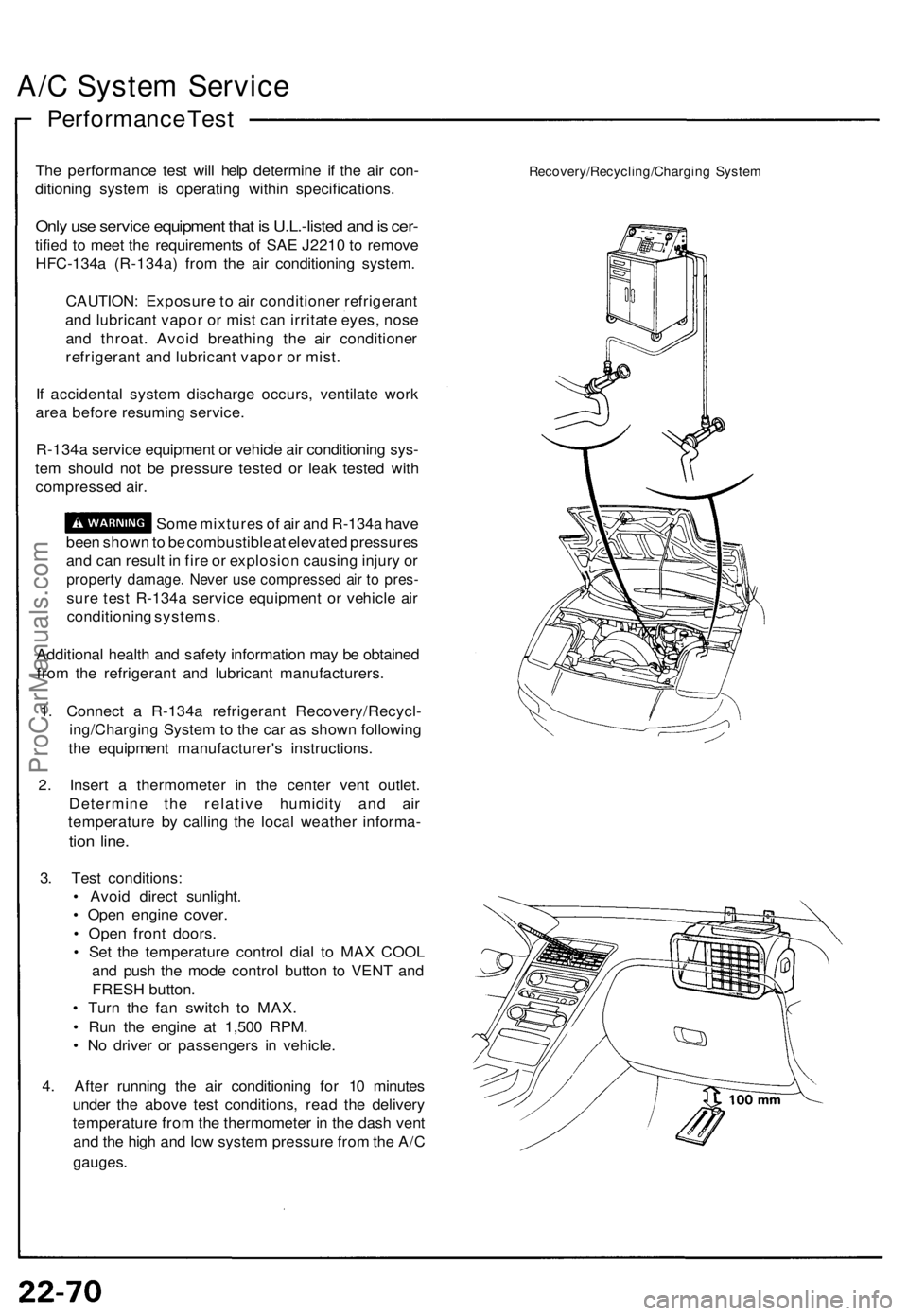
1 . Connec t a R-134 a refrigeran t Recovery/Recycl -
ing/Chargin g Syste m to th e ca r a s show n followin g
th e equipmen t manufacturer' s instructions .
2 . Inser t a thermomete r i n th e cente r ven t outlet .
Determin e th e relativ e humidit y an d ai r
temperatur e b y callin g th e loca l weathe r informa -
tion line .
3. Tes t conditions :
• Avoi d direc t sunlight .
• Ope n engin e cover .
• Ope n fron t doors .
• Se t th e temperatur e contro l dia l t o MA X COO L
an d pus h th e mod e contro l butto n t o VEN T an d
FRES H button .
• Tur n th e fa n switc h t o MAX .
• Ru n th e engin e a t 1,50 0 RPM .
• N o drive r o r passenger s i n vehicle .
4 . Afte r runnin g th e ai r conditionin g fo r 1 0 minute s
unde r th e abov e tes t conditions , rea d th e deliver y
temperatur e fro m th e thermomete r i n th e das h ven t
an d th e hig h an d low syste m pressur e fro m th e A/ C
gauges .
Recovery/Recycling/Chargin g Syste m
ProCarManuals.com