Page 17 of 303
 . . . . . . . . . . . . . . . . . . . . . . . . . . . . . . . . . . . . . . Light alloy
Maximum distortion . . . . . . . . . . . . . . . . . . . . .")
Cylinder head and valves
Material (cylinder head) . . . . . . . . . . . . . . . . . . . . . . . . . . . . . . . . . . . . . . Light alloy
Maximum distortion . . . . . . . . . . . . . . . . . . . . . . . . . . . . . . . . . . . . . . . . 0.05 mm (0.002 in)
Valve guide bore in head . . . . . . . . . . . . . . . . . . . . . . . . . . . . . . . . . . . . 12.950 to 12.977 mm (0.5099 to 0.5109 in)
Valve guide outside diameter . . . . . . . . . . . . . . . . . . . . . . . . . . . . . . . . . 13.010 to 13.030 mm (0.5122 to 0.5130 in)
Valve guide oversizes . . . . . . . . . . . . . . . . . . . . . . . . . . . . . . . . . . . . . . . 0.5, 0.10, 0.25 mm (0.002, 0.004, 0.010 in)
Inside diameter of valve guide (reamed) . . . . . . . . . . . . . . . . . . . . . . . . . 7.022 to 7.040 mm (0.2765 to 0.2772 in)
Guide fit in head (interference) . . . . . . . . . . . . . . . . . . . . . . . . . . . . . . . . 0.033 to 0.080 mm (0.0013 to 0.0032 in)
Valve stem diameter . . . . . . . . . . . . . . . . . . . . . . . . . . . . . . . . . . . . . . . . 6.982 to 7.000 mm (0.2748 to 0.2756 in)
Maximum clearance (valve stem to guide) . . . . . . . . . . . . . . . . . . . . . . . 0.022 to 0.058 mm (0.0009 to 0.0023 in)
Valve seat angle . . . . . . . . . . . . . . . . . . . . . . . . . . . . . . . . . . . . . . . . . . . 44º 55’ to 45º 05’
Valve face angle . . . . . . . . . . . . . . . . . . . . . . . . . . . . . . . . . . . . . . . . . . . 45º 25’ to 45º 35’
Valve head diameter:
Inlet . . . . . . . . . . . . . . . . . . . . . . . . . . . . . . . . . . . . . . . . . . . . . . . . . . . 29.0 mm (1.1417 in)
Exhaust . . . . . . . . . . . . . . . . . . . . . . . . . . . . . . . . . . . . . . . . . . . . . . . . 26.0 mm (1.0236 in)
Contact band (valve to seat) . . . . . . . . . . . . . . . . . . . . . . . . . . . . . . . . . . 1.3 to 1.5 mm (0.0512 to 0.0591 in)
Valve clearance:
Inlet . . . . . . . . . . . . . . . . . . . . . . . . . . . . . . . . . . . . . . . . . . . . . . . . . . . 0.15 mm (0.006 in)
Exhaust . . . . . . . . . . . . . . . . . . . . . . . . . . . . . . . . . . . . . . . . . . . . . . . . 0.20 mm (0.008 in)
For timing check . . . . . . . . . . . . . . . . . . . . . . . . . . . . . . . . . . . . . . . . . . . 0.60 mm (0.024 in)
Valve timing:
Inlet valve:
Opens . . . . . . . . . . . . . . . . . . . . . . . . . . . . . . . . . . . . . . . . . . . . . . . 7º BTDC
Closes . . . . . . . . . . . . . . . . . . . . . . . . . . . . . . . . . . . . . . . . . . . . . . . 36º ABDC
Exhaust valve:
Opens . . . . . . . . . . . . . . . . . . . . . . . . . . . . . . . . . . . . . . . . . . . . . . . 38º BBDC
Closes . . . . . . . . . . . . . . . . . . . . . . . . . . . . . . . . . . . . . . . . . . . . . . . 5º ATDC
Lubrication system
Oil pump type . . . . . . . . . . . . . . . . . . . . . . . . . . . . . . . . . . . . . . . . . . . . . Gear, driven by shaft from camshaft
Tooth tip to body clearance . . . . . . . . . . . . . . . . . . . . . . . . . . . . . . . . . . 0.05 to 0.14 mm (0.0020 to 0.0055 in)
Gear endfloat . . . . . . . . . . . . . . . . . . . . . . . . . . . . . . . . . . . . . . . . . . . . . 0.020 to 0.105 mm (0.0008 to 0.0041 in)
Oil pressure at normal operating temperature and average road/
engine speed . . . . . . . . . . . . . . . . . . . . . . . . . . . . . . . . . . . . . . . . . . . . . 2.94 to 3.92 bar (42 to 57 lbf/ in
2)
Oil capacity (with filter change) . . . . . . . . . . . . . . . . . . . . . . . . . . . . . . . . 3.42 litre (6.0 pint)
Oil type/specification . . . . . . . . . . . . . . . . . . . . . . . . . . . . . . . . . . . . . . . Multigrade engine oil, viscosity SAE 15W/40
Oil filter . . . . . . . . . . . . . . . . . . . . . . . . . . . . . . . . . . . . . . . . . . . . . . . . . . Champion C101
Torque wrench settingsNm lbf ft
Cylinder head bolts:
Stage 1 . . . . . . . . . . . . . . . . . . . . . . . . . . . . . . . . . . . . . . . . . . . . . . . . 30 22
Stage 2 . . . . . . . . . . . . . . . . . . . . . . . . . . . . . . . . . . . . . . . . . . . . . . . . 59 43.5
Camshaft sprocket bolt . . . . . . . . . . . . . . . . . . . . . . . . . . . . . . . . . . . . . 49 36
Main bearing cap bolts . . . . . . . . . . . . . . . . . . . . . . . . . . . . . . . . . . . . . . 69 51
Big-end bearing cap bolts . . . . . . . . . . . . . . . . . . . . . . . . . . . . . . . . . . . 41 30
Crankshaft pulley nut . . . . . . . . . . . . . . . . . . . . . . . . . . . . . . . . . . . . . . . 98 72
Flywheel bolts . . . . . . . . . . . . . . . . . . . . . . . . . . . . . . . . . . . . . . . . . . . . . 44 32
Rocker pedestal nuts . . . . . . . . . . . . . . . . . . . . . . . . . . . . . . . . . . . . . . . 39 29
Engine mounting bracket bolts . . . . . . . . . . . . . . . . . . . . . . . . . . . . . . . . 25 18
Engine mounting centre nuts . . . . . . . . . . . . . . . . . . . . . . . . . . . . . . . . . 49 36
Exhaust manifold nuts . . . . . . . . . . . . . . . . . . . . . . . . . . . . . . . . . . . . . . 20 15
Spark plugs . . . . . . . . . . . . . . . . . . . . . . . . . . . . . . . . . . . . . . . . . . . . . . . 25 18
Temperature sender switch . . . . . . . . . . . . . . . . . . . . . . . . . . . . . . . . . . 49 36
Driveshaft to hub nuts . . . . . . . . . . . . . . . . . . . . . . . . . . . . . . . . . . . . . . 272 200
Hub carrier to strut clamp bolts . . . . . . . . . . . . . . . . . . . . . . . . . . . . . . . 49 36
Roadwheel bolts . . . . . . . . . . . . . . . . . . . . . . . . . . . . . . . . . . . . . . . . . . . 86 63
Brake caliper mounting bolts . . . . . . . . . . . . . . . . . . . . . . . . . . . . . . . . . 53 39
Tie-rod end balljoint nuts . . . . . . . . . . . . . . . . . . . . . . . . . . . . . . . . . . . . 34 25
Driveshaft inboard boot retainer bolts . . . . . . . . . . . . . . . . . . . . . . . . . . 9 7
Engine – general 1•3
1
Page 18 of 303

1116 cc and 1301 cc engine
Type . . . . . . . . . . . . . . . . . . . . . . . . . . . . . . . . . . . . . . . . . . . . . . . . . . . . Four cylinder in-line, liquid cooled single overhead camshaft.
Transversely mounted with end-on transmission
General1116 cc 1301 cc
Bore . . . . . . . . . . . . . . . . . . . . . . . . . . . . . . . . . . . . . . . . . . . . . . . . . . . . 80.0 mm (3.15 in) 86.4 mm (3.40 in)
Stroke . . . . . . . . . . . . . . . . . . . . . . . . . . . . . . . . . . . . . . . . . . . . . . . . . . . 55.5 mm (2.19 in) 55.5 mm (2.19 in)
Displacement . . . . . . . . . . . . . . . . . . . . . . . . . . . . . . . . . . . . . . . . . . . . . 1116 cc (68.08 cu in) 1301 cc (79.36 cu in)
Compression ratio . . . . . . . . . . . . . . . . . . . . . . . . . . . . . . . . . . . . . . . . . 9.2 : 1 9.1 : 1
Maximum power (DIN) . . . . . . . . . . . . . . . . . . . . . . . . . . . . . . . . . . . . . . 40.5 kW (55 bhp) at 5600 rev/min50 kW (68 bhp) at 5700 rev/min
Maximum torque (DIN) . . . . . . . . . . . . . . . . . . . . . . . . . . . . . . . . . . . . . . 86.3 Nm (64 lbf ft) at 100 Nm (74 lbf ft)
2900 rev/min at 2900 rev/min
Compression pressure (bore wear test) . . . . . . . . . . . . . . . . . . . . . . . . . 10.35 to 11.73 bar (150 to 170 lbf/in
2)
Pressure difference between cylinders . . . . . . . . . . . . . . . . . . . . . . . . . . 0.96 bar (14 lbf/ in2)
Firing order . . . . . . . . . . . . . . . . . . . . . . . . . . . . . . . . . . . . . . . . . . . . . . . 1 - 3 - 4 - 2 (No. 1 at crankshaft pulley end)
Pistons and piston rings
Piston diameter - 1116 cc:
Grade A . . . . . . . . . . . . . . . . . . . . . . . . . . . . . . . . . . . . . . . . . . . . . . . . 79.940 to 79.950 mm (3.1496 to 3.1500 in)
Grade C . . . . . . . . . . . . . . . . . . . . . . . . . . . . . . . . . . . . . . . . . . . . . . . . 79.960 to 79.970 mm (3.1504 to 3.1508 in)
Grade E . . . . . . . . . . . . . . . . . . . . . . . . . . . . . . . . . . . . . . . . . . . . . . . . 79.980 to 79.990 mm (3.1512 to 3.1516 in)
Piston diameter - 1301 cc:
Grade A . . . . . . . . . . . . . . . . . . . . . . . . . . . . . . . . . . . . . . . . . . . . . . . . 86.320 to 86.330 mm (3.4010 to 3.4014 in)
Grade C . . . . . . . . . . . . . . . . . . . . . . . . . . . . . . . . . . . . . . . . . . . . . . . . 86.340 to 86.350 mm (3.4018 to 3.4022 in)
Grade E . . . . . . . . . . . . . . . . . . . . . . . . . . . . . . . . . . . . . . . . . . . . . . . . 86.360 to 86.370 mm (3.4025 to 3.4030 in)
Oversizes . . . . . . . . . . . . . . . . . . . . . . . . . . . . . . . . . . . . . . . . . . . . . . . . 0.2, 0.4, 0.6 mm (0.008, 0.016, 0.023 in)
Piston clearance in cylinder bore:
1116 cc . . . . . . . . . . . . . . . . . . . . . . . . . . . . . . . . . . . . . . . . . . . . . . . . 0.050 to 0.070 mm (0.0020 to 0.0027 in)
1301 cc . . . . . . . . . . . . . . . . . . . . . . . . . . . . . . . . . . . . . . . . . . . . . . . . 0.070 to 0.090 mm (0.0027 to 0.0035 in)
Piston ring groove width - 1116 cc:
Top . . . . . . . . . . . . . . . . . . . . . . . . . . . . . . . . . . . . . . . . . . . . . . . . . . . 1.535 to 1.555 mm (0.1442 to 0.1461 in)
Second . . . . . . . . . . . . . . . . . . . . . . . . . . . . . . . . . . . . . . . . . . . . . . . . 2.015 to 2.035 mm (0.0794 to 0.0802 in)
Bottom . . . . . . . . . . . . . . . . . . . . . . . . . . . . . . . . . . . . . . . . . . . . . . . . 3.957 to 3.977 mm (0.1559 to 0.1567 in)
Piston ring groove width - 1301 cc:
Top . . . . . . . . . . . . . . . . . . . . . . . . . . . . . . . . . . . . . . . . . . . . . . . . . . . 1.535 to 1.555 mm (0.0605 to 0.0613 in)
Second . . . . . . . . . . . . . . . . . . . . . . . . . . . . . . . . . . . . . . . . . . . . . . . . 2.030 to 2.050 mm (0.0800 to 0.0808 in)
Bottom . . . . . . . . . . . . . . . . . . . . . . . . . . . . . . . . . . . . . . . . . . . . . . . . 3.967 to 3.987 mm (0.1563 to 0.1571 in)
Piston ring thickness:
Top . . . . . . . . . . . . . . . . . . . . . . . . . . . . . . . . . . . . . . . . . . . . . . . . . . . 1.478 to 1.490 mm (0.0582 to 0.0587 in)
Second . . . . . . . . . . . . . . . . . . . . . . . . . . . . . . . . . . . . . . . . . . . . . . . . 1.978 to 1.990 mm (0.0779 to 0.0784 in)
Bottom . . . . . . . . . . . . . . . . . . . . . . . . . . . . . . . . . . . . . . . . . . . . . . . . 3.925 to 3.937 mm (0.1546 to 0.1551 in)
Oversizes . . . . . . . . . . . . . . . . . . . . . . . . . . . . . . . . . . . . . . . . . . . . . . . . 0.2, 0.4, 0.6 mm (0.008, 0.016, 0.023 in)
Piston ring groove clearance - 1116 cc:
Top . . . . . . . . . . . . . . . . . . . . . . . . . . . . . . . . . . . . . . . . . . . . . . . . . . . 0.045 to 0.077 mm (0.0018 to 0.0030 in)
Second . . . . . . . . . . . . . . . . . . . . . . . . . . . . . . . . . . . . . . . . . . . . . . . . 0.025 to 0.057 mm (0.0010 to 0.0022 in)
Bottom . . . . . . . . . . . . . . . . . . . . . . . . . . . . . . . . . . . . . . . . . . . . . . . . 0.020 to 0.052 mm (0.0008 to 0.0020 in)
Piston ring groove clearance - 1301 cc:
Top . . . . . . . . . . . . . . . . . . . . . . . . . . . . . . . . . . . . . . . . . . . . . . . . . . . 0.045 to 0.077 mm (0.0018 to 0.0030 in)
Second . . . . . . . . . . . . . . . . . . . . . . . . . . . . . . . . . . . . . . . . . . . . . . . . 0.040 to 0.072 mm (0.0016 to 0.0028 in)
Bottom . . . . . . . . . . . . . . . . . . . . . . . . . . . . . . . . . . . . . . . . . . . . . . . . 0.030 to 0.062 mm (0.0012 to 0.0024 in)
Piston ring end gap - 1116 cc:
Top . . . . . . . . . . . . . . . . . . . . . . . . . . . . . . . . . . . . . . . . . . . . . . . . . . . 0.30 to 0.45 mm (0.0012 to 0.0018 in)
Second . . . . . . . . . . . . . . . . . . . . . . . . . . . . . . . . . . . . . . . . . . . . . . . . 0.20 to 0.35 mm (0.008 to 0.014 in)
Bottom . . . . . . . . . . . . . . . . . . . . . . . . . . . . . . . . . . . . . . . . . . . . . . . . 0.20 to 0.35 mm (0.008 to 0.014 in)
Piston ring end gap - 1301 cc:
Top . . . . . . . . . . . . . . . . . . . . . . . . . . . . . . . . . . . . . . . . . . . . . . . . . . . 0.30 to 0.45 mm (0.012 to 0.016 in)
Second . . . . . . . . . . . . . . . . . . . . . . . . . . . . . . . . . . . . . . . . . . . . . . . . 0.30 to 0.50 mm (0.012 to 0.020 in)
Bottom . . . . . . . . . . . . . . . . . . . . . . . . . . . . . . . . . . . . . . . . . . . . . . . . 0.25 to 0.40 mm (0.010 to 0.016 in)
Gudgeon pin diameter - 1116 cc:
Grade 1 . . . . . . . . . . . . . . . . . . . . . . . . . . . . . . . . . . . . . . . . . . . . . . . . 21.970 to 21.974 mm (0.8656 to 0.8658 in)
Grade 2 . . . . . . . . . . . . . . . . . . . . . . . . . . . . . . . . . . . . . . . . . . . . . . . . 21.974 to 21.978 mm (0.8658 to 0.8659 in)
Grade 3 . . . . . . . . . . . . . . . . . . . . . . . . . . . . . . . . . . . . . . . . . . . . . . . . 21.978 to 21.982 mm (0.8659 to 0.8661in)
Gudgeon pin diameter - 1301 cc:
Grade 1 . . . . . . . . . . . . . . . . . . . . . . . . . . . . . . . . . . . . . . . . . . . . . . . . 21.991 to 21.994 mm (0.8664 to 0.8666 in)
Grade 2 . . . . . . . . . . . . . . . . . . . . . . . . . . . . . . . . . . . . . . . . . . . . . . . . 21.994 to 21.997 mm (0.8666 to 0.8667 in)
Oversize . . . . . . . . . . . . . . . . . . . . . . . . . . . . . . . . . . . . . . . . . . . . . . . . . 0.2 mm (0.008 in)
1•4 Engine – general
Page 19 of 303

Standard main bearing shell thickness . . .")
Crankshaft
Journal diameter . . . . . . . . . . . . . . . . . . . . . . . . . . . . . . . . . . . . . . . . . . . 50.785 to 50.805 mm (1.9994 to 2.0002 in)
Standard main bearing shell thickness . . . . . . . . . . . . . . . . . . . . . . . . . . 1.825 to 1.831 mm (0.0719 to 0.0721 in)
Undersizes . . . . . . . . . . . . . . . . . . . . . . . . . . . . . . . . . . . . . . . . . . . . . . . 0.254, 0.508, 0.762, 1.016 mm (0.010. 0.020, 0.030, 0.040 in)
Crankshaft endfloat . . . . . . . . . . . . . . . . . . . . . . . . . . . . . . . . . . . . . . . . 0.06 to 0.26 mm (0.0024 to 0.0102 in)
Crankpin diameter . . . . . . . . . . . . . . . . . . . . . . . . . . . . . . . . . . . . . . . . . 45.498 to 45.518 mm (1.7926 to 1.7934 in)
Standard big-end shell bearing thickness . . . . . . . . . . . . . . . . . . . . . . . 1.531 to 1.538 mm (0.0603 to 0.0606 in)
Undersizes . . . . . . . . . . . . . . . . . . . . . . . . . . . . . . . . . . . . . . . . . . . . . . . 0.254, 0.508, 0.762, 1.016 mm (0.010, 0.020, 0.030, 0.040 in)
Camshaft
Number of bearings . . . . . . . . . . . . . . . . . . . . . . . . . . . . . . . . . . . . . . . . 5
Diameter of camshaft journals:
No. 1 (timing end) . . . . . . . . . . . . . . . . . . . . . . . . . . . . . . . . . . . . . . . . 29.944 to 29.960 mm (1.1798 to 1.1804 in)
No. 2 . . . . . . . . . . . . . . . . . . . . . . . . . . . . . . . . . . . . . . . . . . . . . . . . . . 47.935 to 47.950 mm (1.8886 to 1.8892 in)
No. 3 . . . . . . . . . . . . . . . . . . . . . . . . . . . . . . . . . . . . . . . . . . . . . . . . . . 48.135 to 48.150 mm (1.8965 to 1.8971 in)
No. 4 . . . . . . . . . . . . . . . . . . . . . . . . . . . . . . . . . . . . . . . . . . . . . . . . . . 48.335 to 48.350 mm (1.9044 to 1.9050 in)
No. 5 . . . . . . . . . . . . . . . . . . . . . . . . . . . . . . . . . . . . . . . . . . . . . . . . . . 48.535 to 48.550 mm (1.9122 to 1.9129 in)
Cam lift . . . . . . . . . . . . . . . . . . . . . . . . . . . . . . . . . . . . . . . . . . . . . . . . . . 8.8 mm (0.3467 in)
Camshaft bearing diameters in carrier:
No. 1 . . . . . . . . . . . . . . . . . . . . . . . . . . . . . . . . . . . . . . . . . . . . . . . . . . 29.990 to 30.014 mm (1.1816 to 1.1825 in)
No. 2 . . . . . . . . . . . . . . . . . . . . . . . . . . . . . . . . . . . . . . . . . . . . . . . . . . 47.980 to 48.005 mm (1.8904 to 1.8913 in)
No. 3 . . . . . . . . . . . . . . . . . . . . . . . . . . . . . . . . . . . . . . . . . . . . . . . . . . 48.180 to 48.205 mm (1.8982 to 1.8992 in)
No. 4 . . . . . . . . . . . . . . . . . . . . . . . . . . . . . . . . . . . . . . . . . . . . . . . . . . 48.380 to 48.405 mm (1.9062 to 1.9072 in)
No. 5 . . . . . . . . . . . . . . . . . . . . . . . . . . . . . . . . . . . . . . . . . . . . . . . . . . 48.580 to 48.605 mm (1.9141 to 1.9150 in)
Outside diameter of cam follower . . . . . . . . . . . . . . . . . . . . . . . . . . . . . 36.975 to 36.995 mm (1.4568 to 1.4576 in)
Cam follower running clearance . . . . . . . . . . . . . . . . . . . . . . . . . . . . . . . 0.005 to 0.050 mm (0.0002 to 0.0020 in)
Lubrication system
Oil pump type . . . . . . . . . . . . . . . . . . . . . . . . . . . . . . . . . . . . . . . . . . . . . Gear driven from auxiliary shaft
Tooth tip to body clearance . . . . . . . . . . . . . . . . . . . . . . . . . . . . . . . . . . 0.110 to 0.180 mm (0.0043 to 0.0071 in)
Gear endfloat . . . . . . . . . . . . . . . . . . . . . . . . . . . . . . . . . . . . . . . . . . . . . 0.020 to 0.105 mm (0.0008 to 0.0041 in)
Oil pressure at normal operating temperature and average road/
engine speed . . . . . . . . . . . . . . . . . . . . . . . . . . . . . . . . . . . . . . . . . . . . . 3.43 to 4.9 bar (50 to 71 lbf/in
2)
Oil capacity (with filter change) . . . . . . . . . . . . . . . . . . . . . . . . . . . . . . . . 4.05 litre (7.1 pint)
Oil type/specification . . . . . . . . . . . . . . . . . . . . . . . . . . . . . . . . . . . . . . . Multigrade engine oil, viscosity SAE 15W/40
Oil filter . . . . . . . . . . . . . . . . . . . . . . . . . . . . . . . . . . . . . . . . . . . . . . . . . . Champion C106
Cylinder head and valves
Head material . . . . . . . . . . . . . . . . . . . . . . . . . . . . . . . . . . . . . . . . . . . . . Light alloy
Maximum distortion . . . . . . . . . . . . . . . . . . . . . . . . . . . . . . . . . . . . . . . . 0.05 mm (0.002 in)
Valve guide bore in head . . . . . . . . . . . . . . . . . . . . . . . . . . . . . . . . . . . . 13.950 to 13.977 mm (0.5496 to 0.5507 in)
Valve guide outside diameter . . . . . . . . . . . . . . . . . . . . . . . . . . . . . . . . . 14.040 to 14.058 mm (0.5532 to 0.5539 in)
Valve guide oversizes . . . . . . . . . . . . . . . . . . . . . . . . . . . . . . . . . . . . . . . 0.05, 0.10, 0.25 mm (0.002, 0.004, 0.010 in)
Inside diameter of valve guide (reamed) . . . . . . . . . . . . . . . . . . . . . . . . . 8.022 to 8.040 mm (0.3161 to 0.3168 in)
Valve guide fit in cylinder head (interference) . . . . . . . . . . . . . . . . . . . . . 0.063 to 0.108 mm (0.0025 to 0.0043 in)
Valve stem diameter . . . . . . . . . . . . . . . . . . . . . . . . . . . . . . . . . . . . . . . . 7.974 to 7.992 mm (0.3142 to 0.3149 in)
Maximum clearance (valve stem to guide) . . . . . . . . . . . . . . . . . . . . . . . 0.030 to 0.066 mm (0.0012 to 0.0026 in)
Valve face angle . . . . . . . . . . . . . . . . . . . . . . . . . . . . . . . . . . . . . . . . . . . 45º 25’ to 45º 35’
Valve seat angle . . . . . . . . . . . . . . . . . . . . . . . . . . . . . . . . . . . . . . . . . . . 44º 55’ to 45º 05’
Valve head diameter:
Inlet . . . . . . . . . . . . . . . . . . . . . . . . . . . . . . . . . . . . . . . . . . . . . . . . . . . 35.850 to 36.150 mm (1.4125 to 1.4243 in)
Exhaust . . . . . . . . . . . . . . . . . . . . . . . . . . . . . . . . . . . . . . . . . . . . . . . . 30.850 to 31.450 mm (1.2155 to 1.2391 in)
Contact band (valve to seat) . . . . . . . . . . . . . . . . . . . . . . . . . . . . . . . . . . 1.3 to 1.5 mm (0.0512 to 0.0591 in)
Valve clearance:
Inlet . . . . . . . . . . . . . . . . . . . . . . . . . . . . . . . . . . . . . . . . . . . . . . . . . . . 0.40 mm (0.0158 in)
Exhaust . . . . . . . . . . . . . . . . . . . . . . . . . . . . . . . . . . . . . . . . . . . . . . . . 0.50 mm (0.0197 in)
For timing check . . . . . . . . . . . . . . . . . . . . . . . . . . . . . . . . . . . . . . . . . 0.80 mm (0.0315 in)
Valve clearance adjusting shim thicknesses . . . . . . . . . . . . . . . . . . . . . 3.25 to 4.70 mm (0.128 to 0.185 in), in increments of 0.05 mm
(0.002 in)
Valve timing:
Inlet valve:
Opens . . . . . . . . . . . . . . . . . . . . . . . . . . . . . . . . . . . . . . . . . . . . . . . 7º BTDC
Closes . . . . . . . . . . . . . . . . . . . . . . . . . . . . . . . . . . . . . . . . . . . . . . . 35º ABDC
Exhaust valve:
Opens . . . . . . . . . . . . . . . . . . . . . . . . . . . . . . . . . . . . . . . . . . . . . . . 37º BBDC
Closes . . . . . . . . . . . . . . . . . . . . . . . . . . . . . . . . . . . . . . . . . . . . . . . 5º ATDC
Engine – general 1•5
1
Page 20 of 303
:
No. 1 (timing belt end) . . . . . . . . . . . . . . . . . . . . . . . . . . . . . . . . . . . . . 35.664 to 35.684 mm (1.4052 to 1.4059 in)
No. 2 .")
Auxiliary shaft
Bearing internal diameter (reamed):
No. 1 (timing belt end) . . . . . . . . . . . . . . . . . . . . . . . . . . . . . . . . . . . . . 35.664 to 35.684 mm (1.4052 to 1.4059 in)
No. 2 . . . . . . . . . . . . . . . . . . . . . . . . . . . . . . . . . . . . . . . . . . . . . . . . . . 32.000 to 32.020 mm (1.2608 to 1.2616 in)
Shaft journal diameter:
No. 1 (timing belt end) . . . . . . . . . . . . . . . . . . . . . . . . . . . . . . . . . . . . . 35.593 to 35.618 mm (1.4024 to 1.4033 in)
No. 2 . . . . . . . . . . . . . . . . . . . . . . . . . . . . . . . . . . . . . . . . . . . . . . . . . . 31.940 to 31.960 mm (1.2584 to 1.2592 in)
Cylinder block and crankcase
Material . . . . . . . . . . . . . . . . . . . . . . . . . . . . . . . . . . . . . . . . . . . . . . . . . . Cast-iron
Bore diameter:
1116 cc . . . . . . . . . . . . . . . . . . . . . . . . . . . . . . . . . . . . . . . . . . . . . . . . 80.000 to 80.050 mm (3.152 to 3.154 in)
1301 cc . . . . . . . . . . . . . . . . . . . . . . . . . . . . . . . . . . . . . . . . . . . . . . . . 86.400 to 86.450 mm (3.404 to 3.406 in)
Maximum cylinder bore taper . . . . . . . . . . . . . . . . . . . . . . . . . . . . . . . . . 0.015 mm (0.0006 in)
Maximum cylinder bore ovality . . . . . . . . . . . . . . . . . . . . . . . . . . . . . . . . 0.015 mm (0.0006 in)
Torque wrench settingsNm lbf ft
Cylinder head bolts:
Stage 1 . . . . . . . . . . . . . . . . . . . . . . . . . . . . . . . . . . . . . . . . . . . . . . . . 20 15
Stage 2 . . . . . . . . . . . . . . . . . . . . . . . . . . . . . . . . . . . . . . . . . . . . . . . . 40 30
Stage 3 . . . . . . . . . . . . . . . . . . . . . . . . . . . . . . . . . . . . . . . . . . . . . . . . Turn through 90º Turn through 90º
Stage 4 . . . . . . . . . . . . . . . . . . . . . . . . . . . . . . . . . . . . . . . . . . . . . . . . Turn through 90º Turn through 90º
Camshaft carrier to cylinder head . . . . . . . . . . . . . . . . . . . . . . . . . . . . . 20 15
Main bearing cap bolts . . . . . . . . . . . . . . . . . . . . . . . . . . . . . . . . . . . . . . 80 59
Big-end cap nuts . . . . . . . . . . . . . . . . . . . . . . . . . . . . . . . . . . . . . . . . . . 51 38
Flywheel mounting bolts . . . . . . . . . . . . . . . . . . . . . . . . . . . . . . . . . . . . . 83 61
Camshaft sprocket bolt . . . . . . . . . . . . . . . . . . . . . . . . . . . . . . . . . . . . . 83 61
Belt tensioner bolt . . . . . . . . . . . . . . . . . . . . . . . . . . . . . . . . . . . . . . . . . . 44 32
Exhaust manifold nuts . . . . . . . . . . . . . . . . . . . . . . . . . . . . . . . . . . . . . . 28 21
Auxiliary shaft sprocket bolt . . . . . . . . . . . . . . . . . . . . . . . . . . . . . . . . . . 83 61
Flexible mounting bracket bolts . . . . . . . . . . . . . . . . . . . . . . . . . . . . . . . 59 44
Flexible mounting centre nuts . . . . . . . . . . . . . . . . . . . . . . . . . . . . . . . . 49 36
Oil pressure switch . . . . . . . . . . . . . . . . . . . . . . . . . . . . . . . . . . . . . . . . . 32 24
Spark plugs . . . . . . . . . . . . . . . . . . . . . . . . . . . . . . . . . . . . . . . . . . . . . . . 25 18
Roadwheel bolts . . . . . . . . . . . . . . . . . . . . . . . . . . . . . . . . . . . . . . . . . . . 86 63
Driveshaft/hub nuts . . . . . . . . . . . . . . . . . . . . . . . . . . . . . . . . . . . . . . . . 272 200
Tie-rod end balljoint nuts . . . . . . . . . . . . . . . . . . . . . . . . . . . . . . . . . . . . 34 25
Brake caliper mounting bolts . . . . . . . . . . . . . . . . . . . . . . . . . . . . . . . . . 53 39
Front strut lower clamp bolts . . . . . . . . . . . . . . . . . . . . . . . . . . . . . . . . . 49 36
Driveshaft inboard boot retainer bolts . . . . . . . . . . . . . . . . . . . . . . . . . . 9 7
Crankshaft pulley nut . . . . . . . . . . . . . . . . . . . . . . . . . . . . . . . . . . . . . . . 98 7
1•6 Engine – general
Part 1: General
1 Description
1The Uno may be powered by one of three
engines depending upon the particular model.
903 cc
2This is of four cylinder overhead valve type
with a light alloy cylinder head and a cast-iron
block and crankcase.
3A three bearing crankshaft is used and the
chain-driven camshaft runs in three steel
backed white metal bearings.
4The light alloy pistons are fitted with two
compression and one oil control ring. The
gudgeon pin is an interference fit in the small
end of the connecting rod.
5Lubrication is provided by an oil pump
within the sump pan and both the pump and
the distributor are driven from a gear on the
camshaft. Pressurised oil passes through acartridge type oil filter. An oil pressure relief
valve is incorporated in the oil pump. The
engine oil is independent of the transmission
lubricant.
1116 cc and 1301 cc
6These engines are of single overhead
camshaft type, the camshaft being driven by a
toothed belt.
7The difference in engine capacity is
achieved by increasing the cylinder bore on
the 1301 cc engine.
8The cylinder head is of light alloy while the
cylinder block and crankcase are of cast-iron
construction.
9A five bearing crankshaft is used and the
camshaft runs in a similar number of bearings,
but as these are in-line bored directly in the
camshaft carrier, no repair is possible.
10The pistons are of light alloy with two
compression and one oil control ring. The
gudgeon pin is an interference fit in the small
end of the connecting rod.
11An auxiliary shaft, driven by the timing belt
is used to drive the distributor, oil pump and
fuel pump.12The oil pump is located within the sump
pan and incorporates a pressure relief valve.
13Pressurised oil passes through a cartridge
type oil filter.
14The crankshaft main bearings are
supplied under pressure from drillings in the
crankcase from the main oil gallery whilst the
connecting rod big-end bearings are
lubricated from the main bearings by oil
forced through the crankshaft oilways. The
camshaft bearings are fed from a drilling from
the main oil gallery. The cams and tappets are
lubricated by oil mist from outlets in the
camshaft bearings.
15The cylinder walls, pistons and gudgeon
pins are lubricated by oil splashed up by the
crankshaft webs. An oil pressure warning light
is fitted to indicate when the pressure is too
low.
All engines
16The engine is mounted transversely with
the transmission at the front of the car.
17The engine oil is independent of the
transmission lubricant.
Page 21 of 303
Engine – general 1•7
Fig. 1.1 Longitudinal section of 903 cc engine (Sec 1)
Fig. 1.3 Longitudinal section of 1116 cc and 1301 cc engines
(Sec 1)
Fig. 1.2 Cross-section of 903 cc engine (Sec 1)
Fig. 1.4 Cross-section of 1116 cc and 1301 cc engines
(Sec 1)
1
Page 22 of 303
. Preferably check the level
cold, first thing in the morning or if the engine
ha")
2 Engine oil and filter
1
1The engine oil level should be checked at
the weekly service (see “Routine
Maintenance”). Preferably check the level
cold, first thing in the morning or if the engine
has been running, allow at least ten minutes
to elapse after switching off to permit the oil to
drain.
2Withdraw the dipstick, wipe it clean on
non-fluffy material, re-insert it and then
withdraw it for the second time (photo).
3The oil level should be between the MIN
and MAX marks. If not, top up with specified
oil to the MAX mark. Pour the oil slowlythrough the filler orifice on the rocker cover.
To raise the oil level from MIN to MAX will
require approximately 1.1 litre (2.0 pints)
(photos).
4At the intervals specified in “Routine
Maintenance” the oil and filter should be
renewed.
5Have the engine at normal operating
temperature, remove the oil filler cap.
6Place a suitable container under the sump
pan. Unscrew and remove the oil drain plug
and allow the oil to drain (photo).
7While the oil is draining, unscrew and
discard the oil filter. To unscrew the filter, a
filter or chain wrench will normally be
required. If such a tool is not available, drive a
long screwdriver through the oil tester casing
and use it as a lever to unscrew the filter
cartridge.
8Smear the rubber sealing ring of the new oil
filter with oil and screw into position using
hand pressure only (photo).
9Refit the drain plug and refill the engine with
the correct quantity and grade of oil.
10Start the engine. It will take two or three
seconds for the oil warning lamp to go out.
This is normal and is due to the time taken for
the new filter to fill with oil.
11Switch off, check for leaks and check the
oil level, topping up if necessary.
3 Crankcase ventilation
system
1
1This system is designed to draw oil fumes
and blow-by gas (which has passed the piston
rings) from the crankcase and draw it into the
intake manifold when it will then be burned
during the normal combustion process.
2Regularly check the security of the system
hoses which run from the rocker cover or
crankcase breather unit (photo).
3Periodically, detach the hoses and clean
them out with paraffin and a brush or rag pull
through.
4Evidence of sludge or emulsified oil within
the hoses or inside the oil filler cap will
indicate that the engine is running too cool
particularly if the car is used mainly for short
journeys where the engine never reaches full
working temperature.
4 Major operations possible
without removing engine
from car
1The following work can be carried out without
the need to remove the engine from the car.
903 cc engine
Valve clearances - checking and adjusting
Timing chain and sprockets - removal and
refitting
1•8 Engine – general
3.2 Crankcase vent hose (1116 cc)Fig. 1.5 Sectional view of oil filter. Bypass
valve arrowed (Sec 2)2.8 Screwing on the oil filter (903 cc)
2.6 Engine sump drain plug
2.3B Topping up engine oil (1116 cc)2.3A Typical dipstick markings2.2 Withdrawing engine oil dipstick
(1116 cc)
Page 23 of 303

Cylinder head - removal and refitting
Sump pan - removal and refitting
Pistons/connecting rods - removal and
refitting
Oil pump - removal and refitting
Engine mountings - renewal
1116 cc and 1301 cc engines
Valve clearances - checking and adjusting
Camshaft and camshaft carrier - removal
and refitting
Timing belt - removal and refitting
Cylinder head - removal and refitting
Sump pan - removal and refitting
Oil pump - removal and refitting
Pistons/connecting rods - removal and
refitting
Engine mountings - renewal
Part 2:
903 cc engine
5 Valve clearances-
adjustment
2
1Adjust the valves when the engine is cold.
2Unbolt and remove the rocker cover.
3It is important that the clearance is set
when the cam follower of the valve being
adjusted is on the heel of the cam (ie;
opposite the peak). This can be done by
carrying out the adjustments in the following
order, which also avoids turning the
crankshaft more than necessary.
4Turn the crankshaft either using a spanner
on the pulley nut or by raising a front
roadwheel, engaging a gear (3rd or 4th) and
turning the wheel in the forward direction of
travel. It will be easier to turn the engine if the
spark plugs are first removed.
Valve fully open Check and adjust
Valve No. 8 EX Valve No. 1 EX
Valve No. 6 IN Valve No. 3 IN
Valve No. 4 EX Valve No. 5 EX
Valve No. 7 IN Valve No. 2 IN
Valve No. 1 EX Valve No. 8 EX
Valve No. 3 IN Valve No. 6 IN
Valve No. 5 EX Valve No. 4 EX
Valve No. 2 IN Valve No. 7 IN5Count the valves from the timing cover end
of the engine.
6Remember, the inlet and exhaust valve
clearances are different.
7Insert the appropriate feeler gauge between
the end of the valve stem and the rocker arm.
It should be a stiff sliding fit (photo).
8If the clearance is incorrect, release the
rocker arm adjuster screw locknut using a ring
spanner. Turn the adjuster screw using a
small open-ended spanner, but tie something
to it in case it is inadvertently dropped
through one of the pushrod holes.
9Once the clearance is correct, tighten the
locknut without moving the position of the
adjuster screw.
10Repeat the operations on the remaining
seven valves.
11Re-check all the clearances. Make sure
that the rocker cover gasket is in good
condition and fit the rocker cover.
6 Timing chain and sprockets
- removal and refitting
3
1Remove the alternator drivebelt as
described in Chapter 2.
2Unscrew and remove the crankshaft pulley
nut.3Disconnect the hoses from the fuel pump.
4Unbolt and remove the fuel pump with
spacer and rod.
5Support the engine on a hoist or under the
sump and disconnect and remove the
right-hand mounting. Then unscrew and
remove the timing cover bolts. The base of
the cover is secured by the front two sump
pan studs. Unbolt and lower the front end of
the sump. Avoid breaking the gasket. Remove
the timing cover.
6Undo and remove the camshaft sprocket
securing bolt; this will also release the fuel
pump drive cam from the end of the camshaft.
Note the timing marks on the camshaft and
crankshaft sprockets.
7Using two tyre levers, carefully ease the two
sprockets forwards away from the crankcase.
Lift away the two sprockets and timing chain.
8Remove the Woodruff key from the
crankshaft nose with a pair of pliers and note
how the channel in the pulley is designed to fit
over it. Place the Woodruff key in a container
as it is a very small part and can easily
become lost. The camshaft sprocket is
located on the camshaft by a dowel peg.Refitting
9Fit the Woodruff key to the front of the
crankshaft.
10Tap the crankshaft sprocket onto the front
of the crankshaft.
11Turn the sprocket so that the Woodruff
key is uppermost.
12Turn the camshaft until it is in such a
position that if the sprocket was fitted the
dimple timing mark on the sprocket would be
nearest to and in alignment with, the one on
the crankshaft sprocket.
903 cc engine 1•9
5.7 Adjusting a valve clearance
1 Sprocket retaining bolt
2 Fuel pump eccentric cam
3 Timing chain4 Camshaft sprocket
5 Sprocket locating dowel
6 Camshaft7 Woodruff key
8 Crankshaft
9 Crankshaft sprocket
Fig. 1.6 Timing chain and sprockets (Sec 6)
1
To prevent the crankshaft
rotating, either select a gear
and have an assistant apply
the footbrake hard or
remove the starter motor and lock the
ring gear teeth with a large cold chisel
or screwdriver.
Page 24 of 303

13Engage the timing chain with the teeth of
the crankshaft sprocket. Then locate the
camshaft sprocket within the upper loop of
the chain in such a way that when the
sprocket is pushed onto the camshaft, the
timing marks will be in alignment. Make sure
that the self-tensioning links are on the inside
of the chain against the cylinder block
(photos).
14Place the camshaft sprocket onto the
camshaft so that its positioning dowel
engages.
15Secure the camshaft sprocket by fitting
the special cam, that drives the fuel pump, on
its locating dowel. Fit the camshaft sprocket
retaining bolt (photo).
16Tighten the sprocket bolt to the specified
torque.
17If the timing cover oil seal showed signs of
leaking before engine overhaul the old seal
should be removed and a new one fitted.
18Using a screwdriver, carefully remove the
old oil seal, working from the rear of the cover.
Fit the new seal making sure it is inserted
squarely, and tap home with a hammer.
19Lubricate the oil seal with engine oil.
20With all traces of old gasket and jointing
compound removed from the timing cover
and cylinder block mating faces, smear a little
grease onto the timing cover mating face and
fit a new gasket in position.
21Fit the timing cover to the cylinder block
and finger tighten the securing bolts, and
spring washer. Ensure that the fuel pump
pushrod bush is in place in the cover.22Wipe the hub of the pulley and carefully
place into position on the crankshaft. It should
locate on the Woodruff key. It may be
necessary to adjust the position of the timing
cover slightly in order to centralise the oil seal
relative to the pulley hub.
23Tighten the timing cover securing bolts in
a diagonal and progressive manner.
24Tighten the crankshaft pulley nut to the
specified torque again holding the crankshaft
against rotation as previously described
(paragraph 2) this Section.
25Refit the fuel pump and alternator
drivebelt.
7 Cylinder head-
removal and refitting
3
1For safety reasons, disconnect the battery
negative lead.
2Refer to Chapter 2 and drain the cooling
system.
3Refer to Chapter 3 and remove the
carburettor, air cleaner and spacer block.
4Undo and remove the five nuts and
washers securing the exhaust manifold and
hot air ducting to the cylinder head.
5Detach the cable from the temperature
indicator sender unit.
6Refer to Chapter 4 and disconnect the
distributor LT lead and the coil HT lead.
7Refer to Chapter 2 and remove the
thermostat housing from the cylinder head.
8Disconnect the coolant hoses from the
cylinder head.
9Note the electrical connections to the rear
of the alternator and disconnect them.
10Disconnect the mounting and adjuster link
bolts and remove the alternator from the
engine.
11Unscrew the four nuts securing the rocker
cover to the top of the cylinder head and lift
away the spring washers and metal packing
pieces. Remove the rocker cover and cork
gasket.
12Unscrew the four rocker pedestal
securing nuts in a progressive manner. Lift
away the four nuts and spring washers andease the valve rocker assembly from the
cylinder head studs.
13Remove the pushrods, keeping them in
the relative order in which they were removed.
The easiest way to do this is to push them
through a sheet of thick paper or thin card in
the correct sequence.
14Unscrew the cylinder head securing bolts
half a turn at a time in the reverse order to that
shown in Fig. 1.7; don’t forget the one within
the inlet manifold. When all the bolts are no
longer under tension they may be unscrewed
from the cylinder head one at a time. This will
also release a section of the cooling system
pipe secured by two of the bolts. All the bolts
have washers.
15The cylinder head may now be lifted off. If
the head is jammed, try to rock it to break the
seal. Under no circumstances try to prise it
apart from the cylinder block with a
screwdriver or cold chisel as damage may be
done to the faces of the head or block. If this
or the Hint, fail to work, strike the head
sharply with a plastic headed hammer, or with
a wooden hammer, or with a metal hammer
with an interposed piece of wood to cushion
the blows. Under no circumstances hit the
head directly with a metal hammer as this may
cause the casting to fracture. Several sharp
taps with the hammer, at the same time
pulling upwards, should free the head. Lift the
head off and place on one side.
16The cylinder head may now be de-
carbonised or dismantled, refer to Section 17.
Refitting
17After checking that both the cylinder block
and cylinder head mating surfaces are
perfectly clean, generously lubricate each
cylinder with engine oil.
18Always use a new cylinder head gasket as
the old gasket will be compressed and not
capable of giving a good seal.
1•10 903 cc engine
6.15 Fitting fuel pump drive cam and
sprocket bolt
6.13C Self-tensioning links on inside of
chain6.13B Timing mark alignment6.13A Fitting the sprockets and timing
chain
If the head will not readily
free, turn the crankshaft.
The compression generated
in the cylinders will often
break the gasket joint
 1
1 2
2 3
3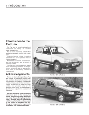 4
4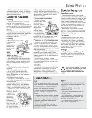 5
5 6
6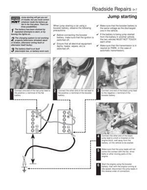 7
7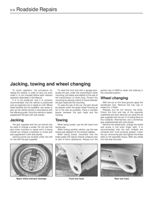 8
8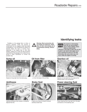 9
9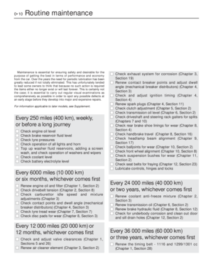 10
10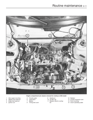 11
11 12
12 13
13 14
14 15
15 16
16 17
17 18
18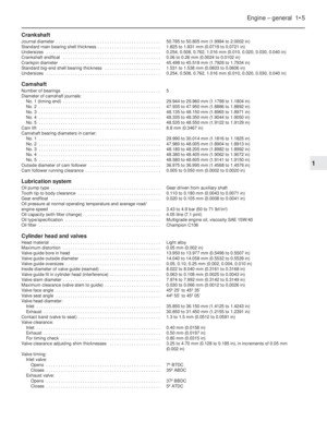 19
19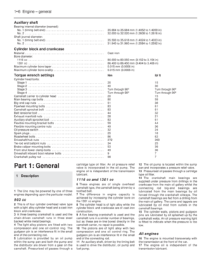 20
20 21
21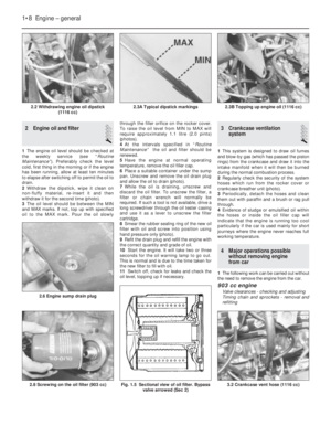 22
22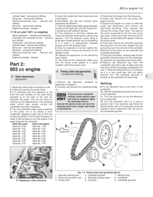 23
23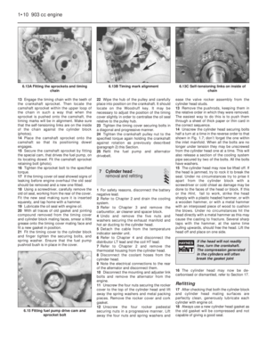 24
24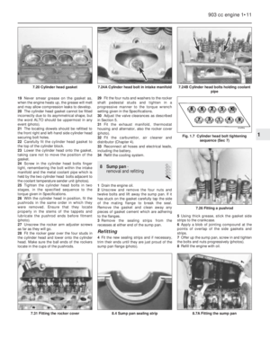 25
25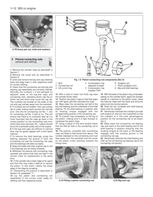 26
26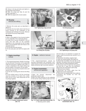 27
27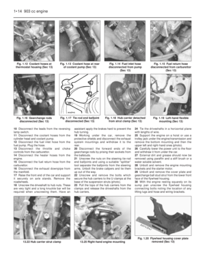 28
28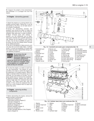 29
29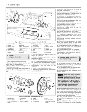 30
30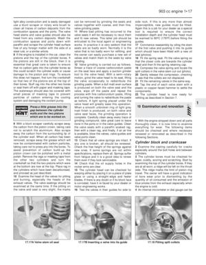 31
31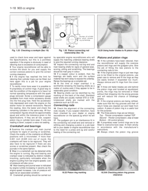 32
32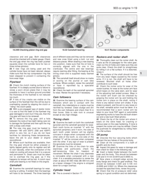 33
33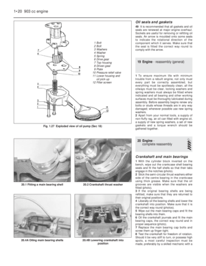 34
34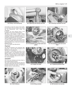 35
35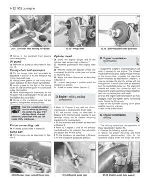 36
36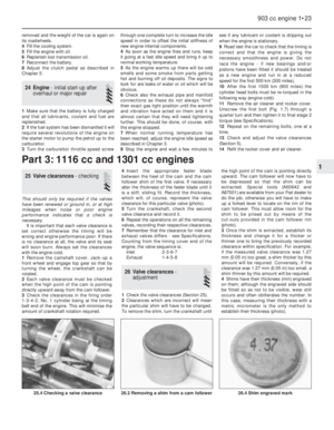 37
37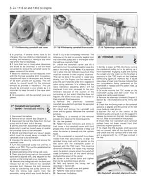 38
38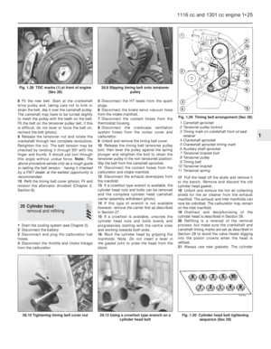 39
39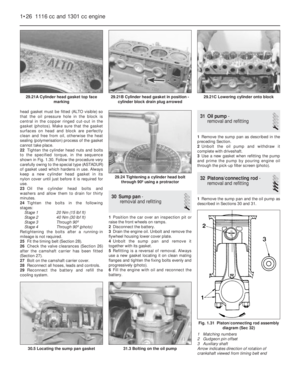 40
40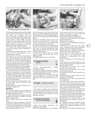 41
41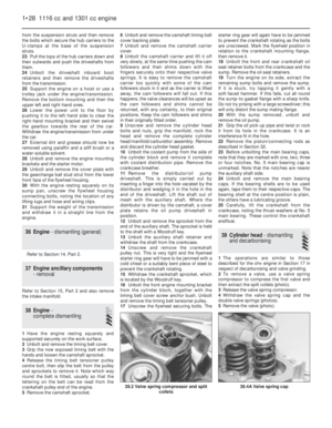 42
42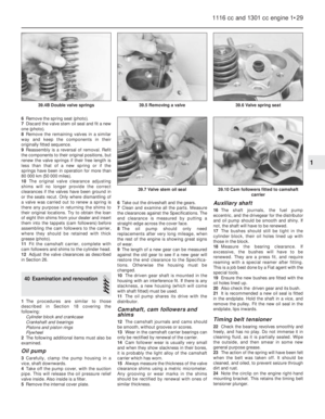 43
43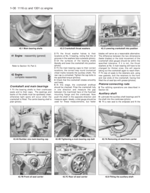 44
44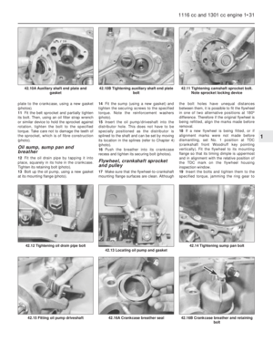 45
45 46
46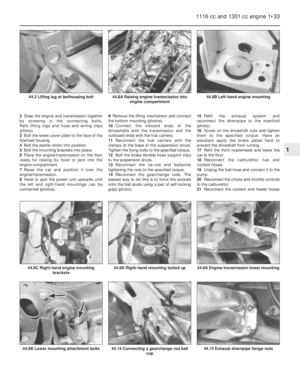 47
47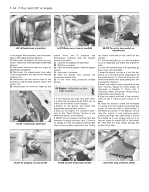 48
48 49
49 50
50 51
51 52
52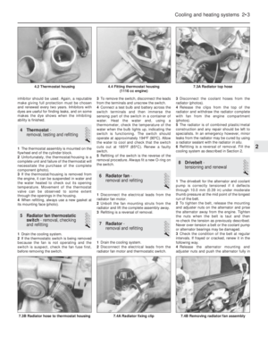 53
53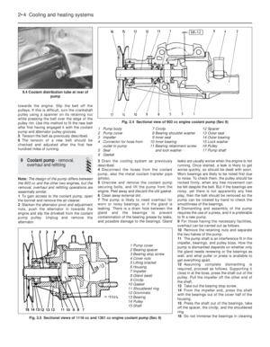 54
54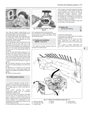 55
55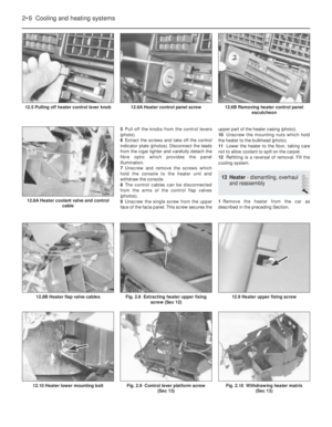 56
56 57
57 58
58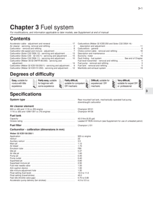 59
59 60
60 61
61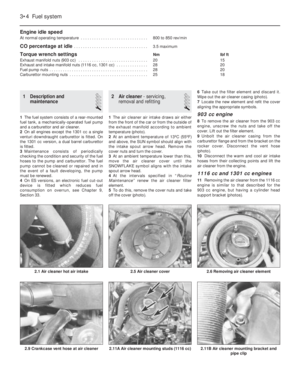 62
62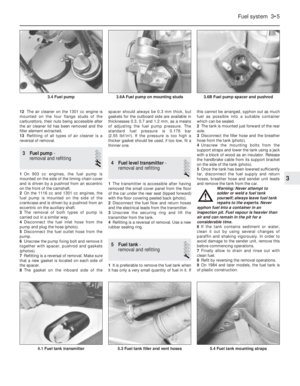 63
63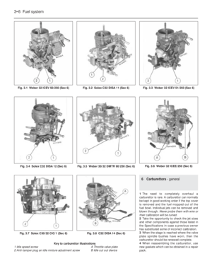 64
64 65
65 66
66 67
67 68
68 69
69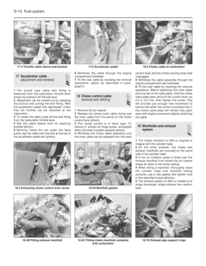 70
70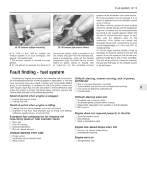 71
71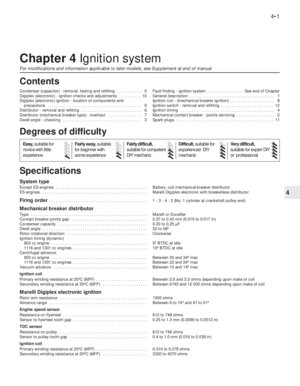 72
72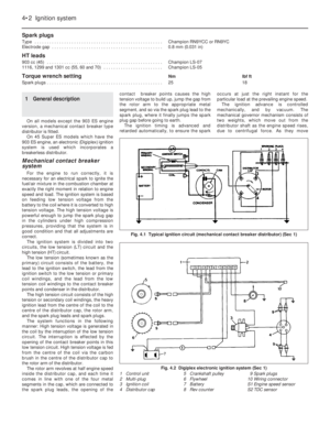 73
73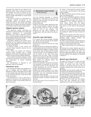 74
74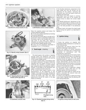 75
75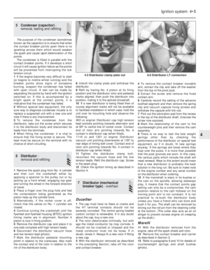 76
76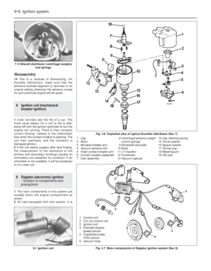 77
77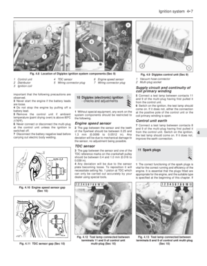 78
78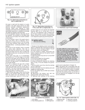 79
79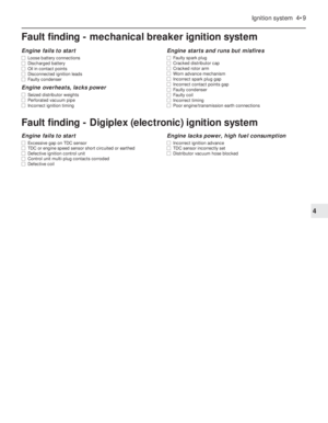 80
80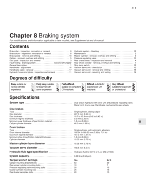 81
81 82
82 83
83 84
84 85
85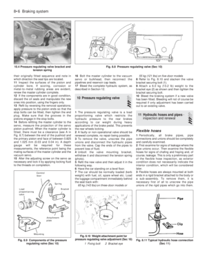 86
86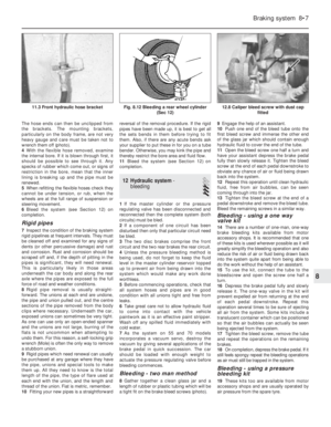 87
87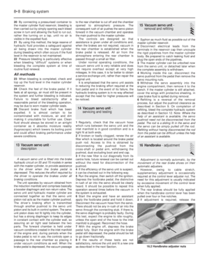 88
88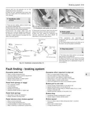 89
89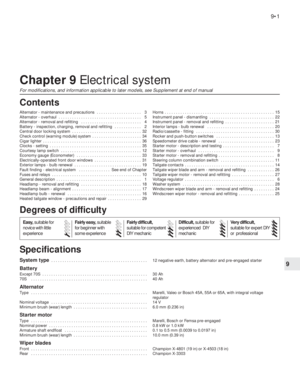 90
90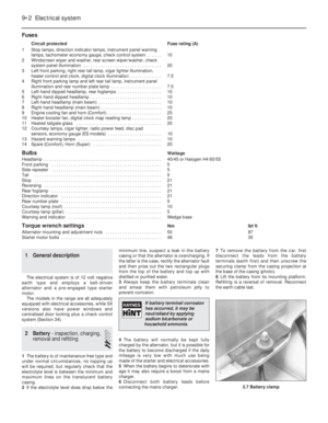 91
91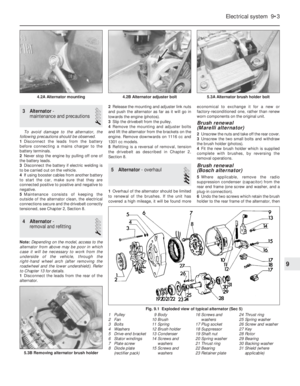 92
92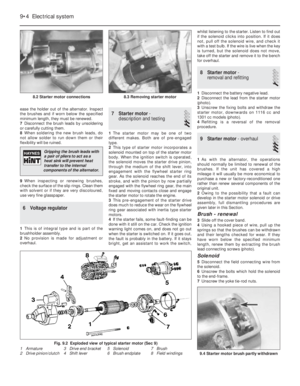 93
93 94
94 95
95 96
96 97
97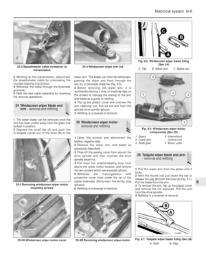 98
98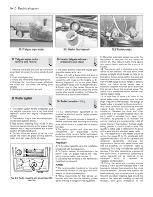 99
99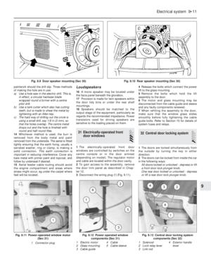 100
100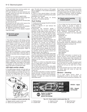 101
101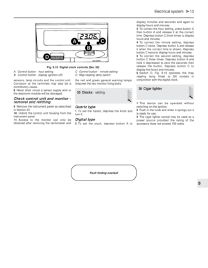 102
102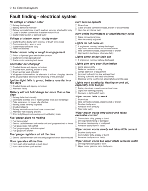 103
103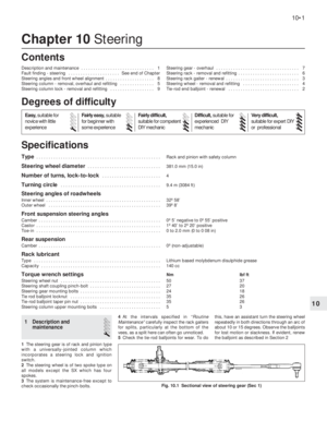 104
104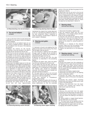 105
105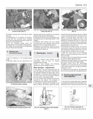 106
106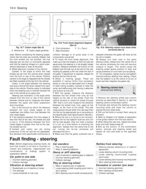 107
107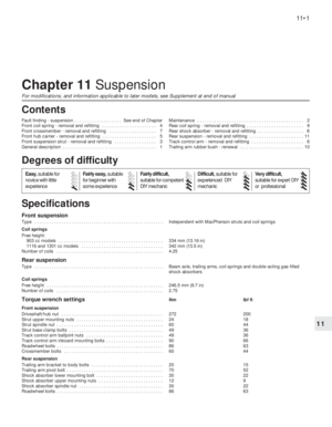 108
108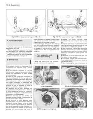 109
109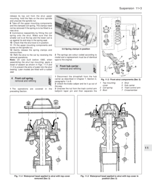 110
110 111
111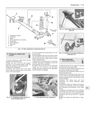 112
112 113
113 114
114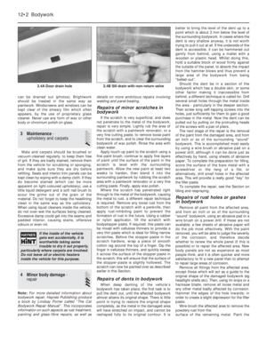 115
115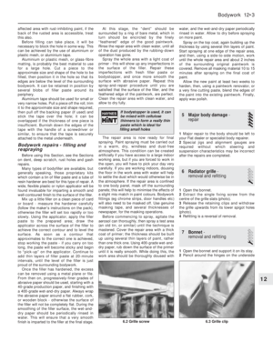 116
116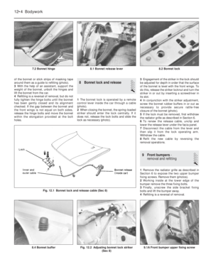 117
117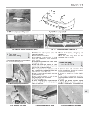 118
118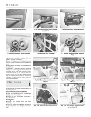 119
119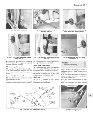 120
120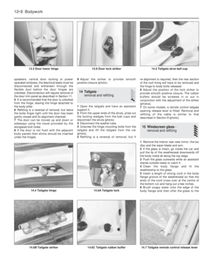 121
121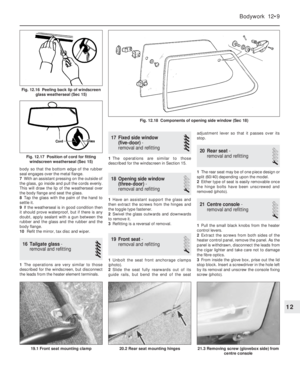 122
122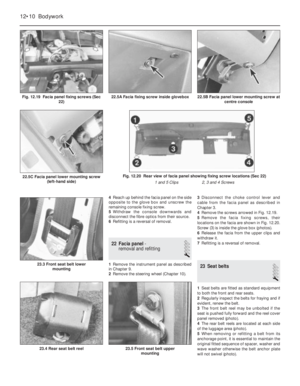 123
123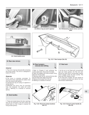 124
124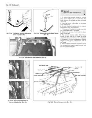 125
125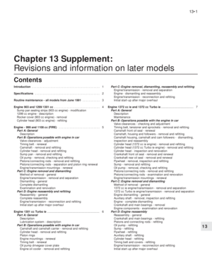 126
126 127
127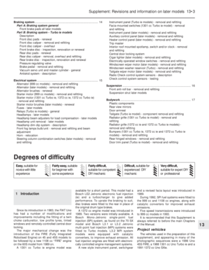 128
128 129
129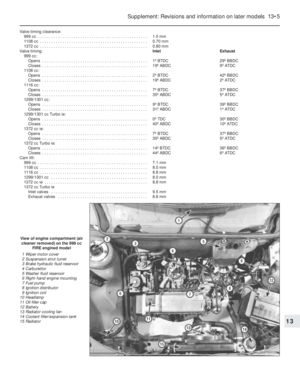 130
130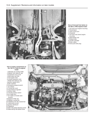 131
131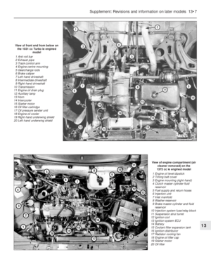 132
132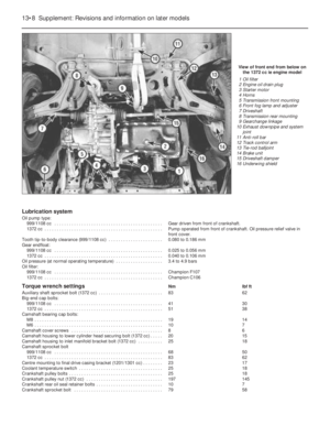 133
133 134
134 135
135 136
136 137
137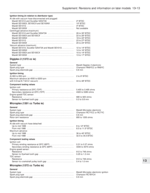 138
138 139
139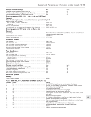 140
140 141
141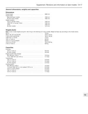 142
142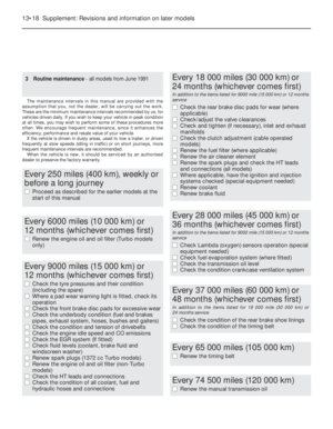 143
143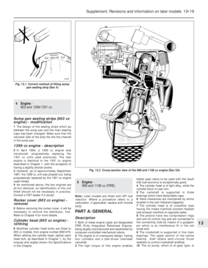 144
144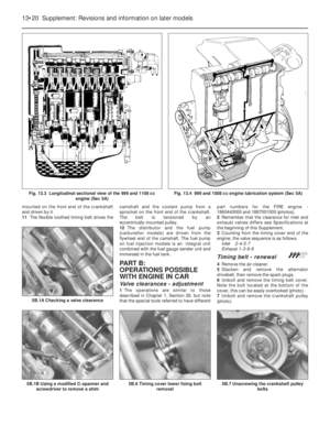 145
145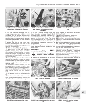 146
146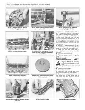 147
147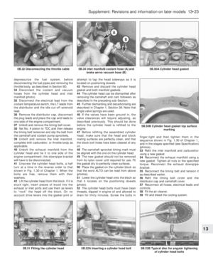 148
148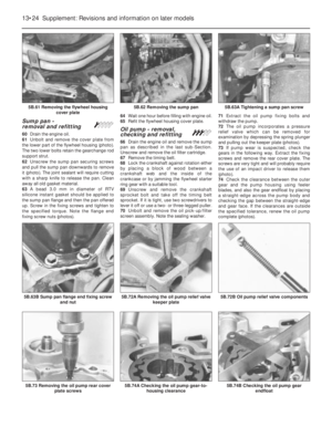 149
149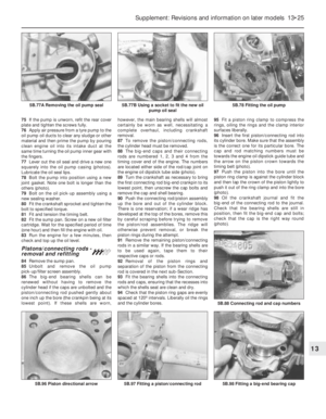 150
150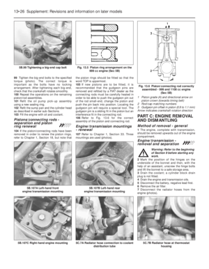 151
151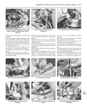 152
152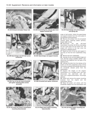 153
153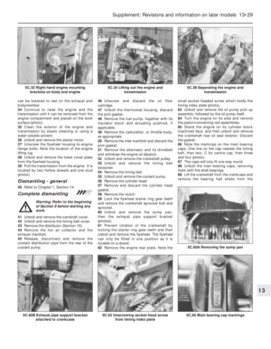 154
154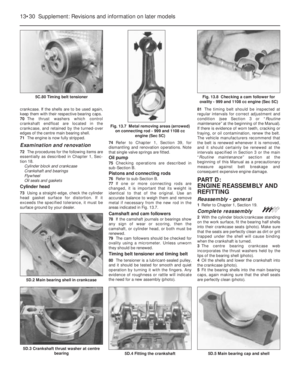 155
155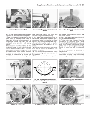 156
156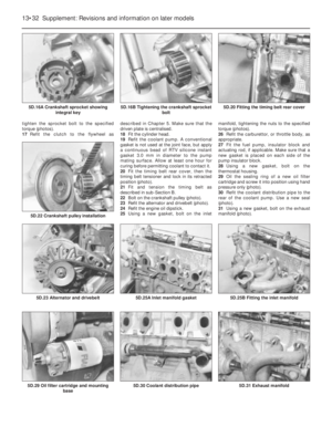 157
157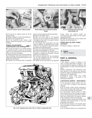 158
158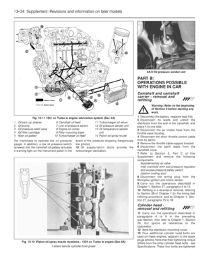 159
159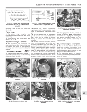 160
160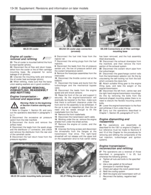 161
161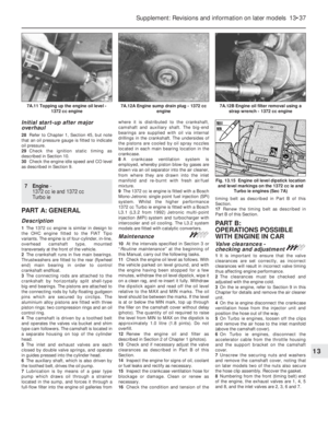 162
162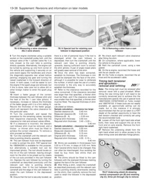 163
163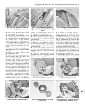 164
164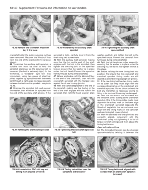 165
165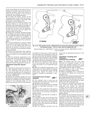 166
166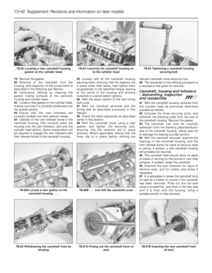 167
167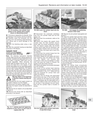 168
168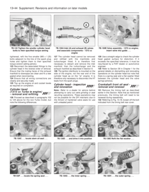 169
169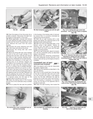 170
170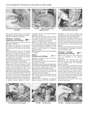 171
171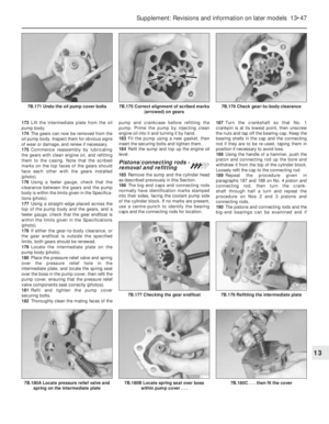 172
172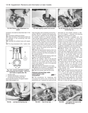 173
173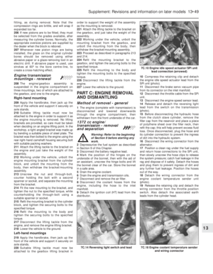 174
174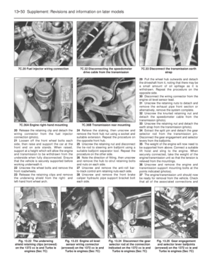 175
175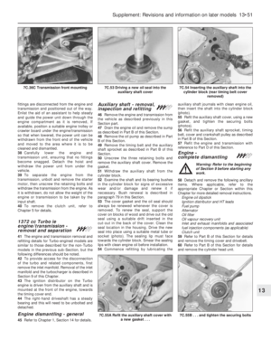 176
176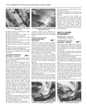 177
177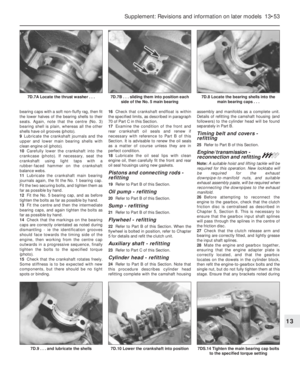 178
178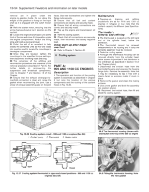 179
179 180
180 181
181 182
182 183
183 184
184 185
185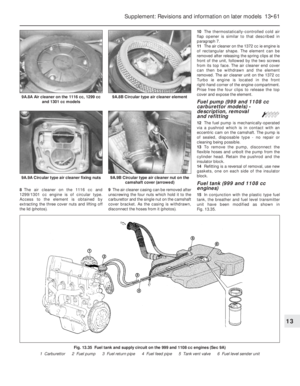 186
186 187
187 188
188 189
189 190
190 191
191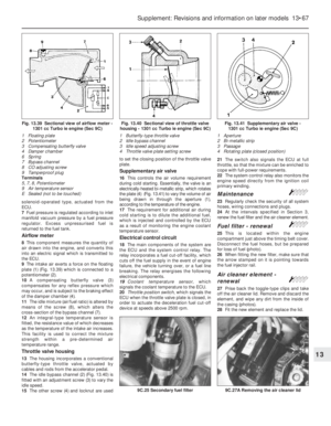 192
192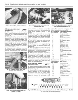 193
193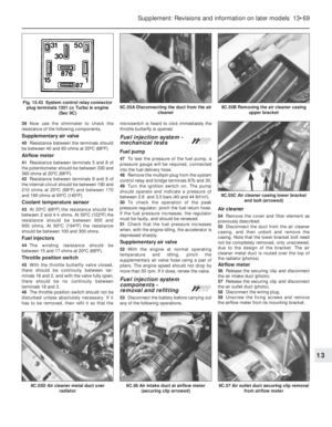 194
194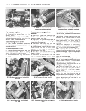 195
195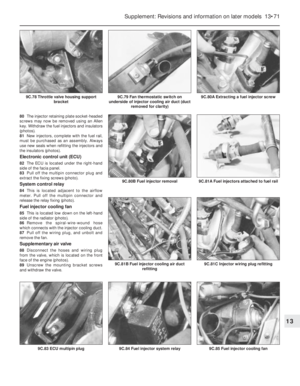 196
196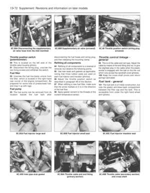 197
197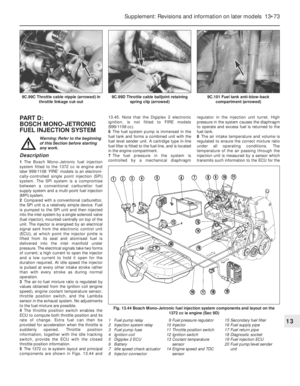 198
198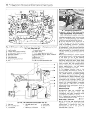 199
199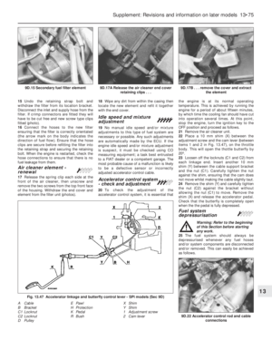 200
200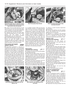 201
201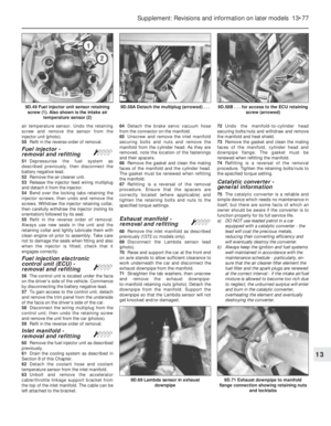 202
202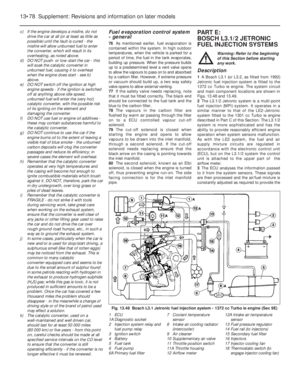 203
203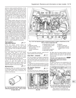 204
204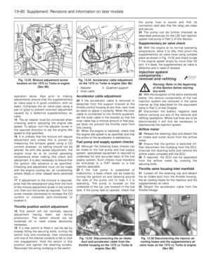 205
205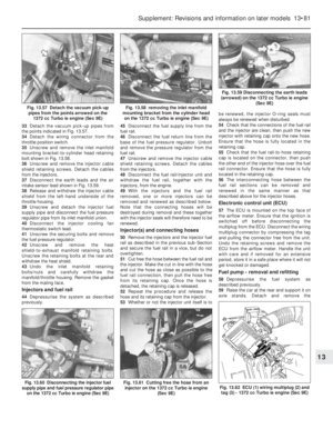 206
206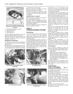 207
207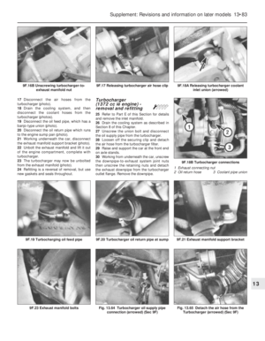 208
208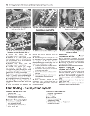 209
209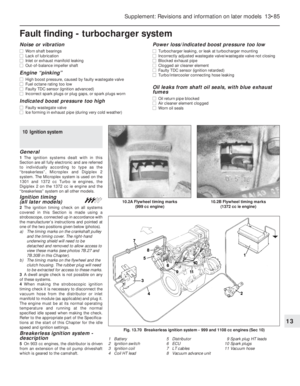 210
210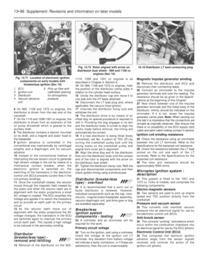 211
211 212
212 213
213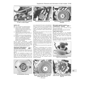 214
214 215
215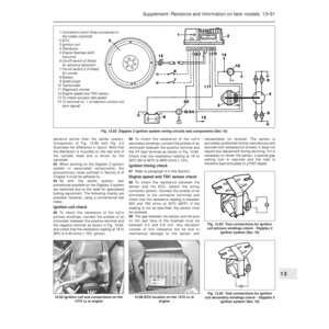 216
216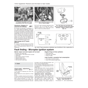 217
217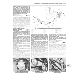 218
218 219
219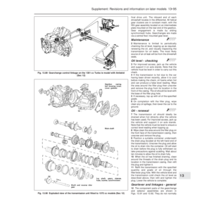 220
220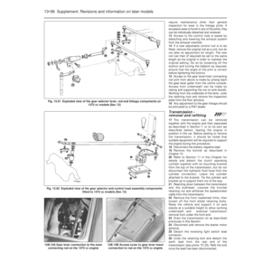 221
221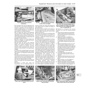 222
222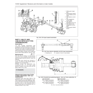 223
223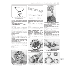 224
224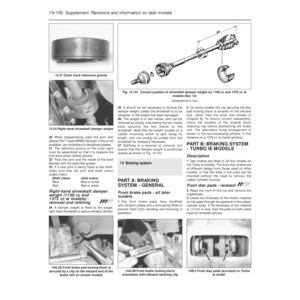 225
225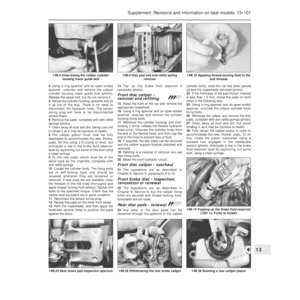 226
226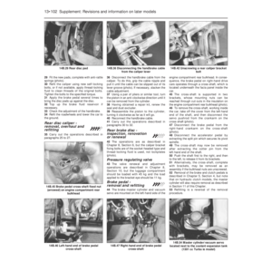 227
227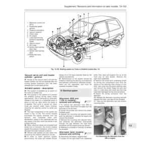 228
228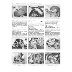 229
229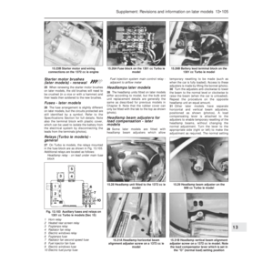 230
230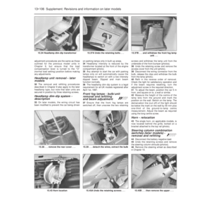 231
231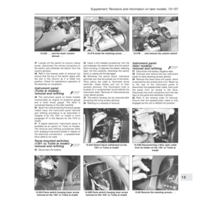 232
232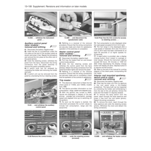 233
233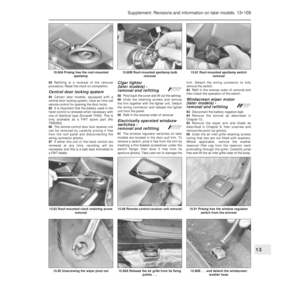 234
234 235
235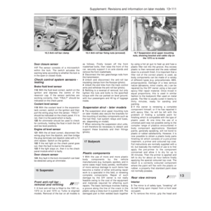 236
236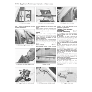 237
237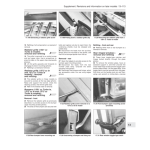 238
238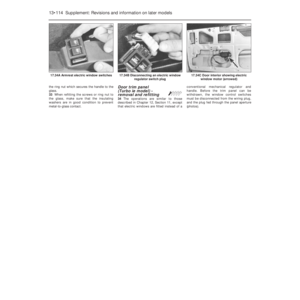 239
239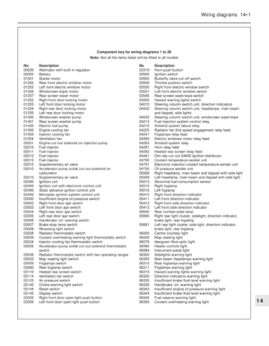 240
240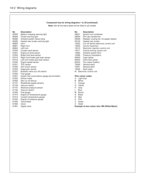 241
241 242
242 243
243 244
244 245
245 246
246 247
247 248
248 249
249 250
250 251
251 252
252 253
253 254
254 255
255 256
256 257
257 258
258 259
259 260
260 261
261 262
262 263
263 264
264 265
265 266
266 267
267 268
268 269
269 270
270 271
271 272
272 273
273 274
274 275
275 276
276 277
277 278
278 279
279 280
280 281
281 282
282 283
283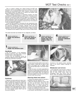 284
284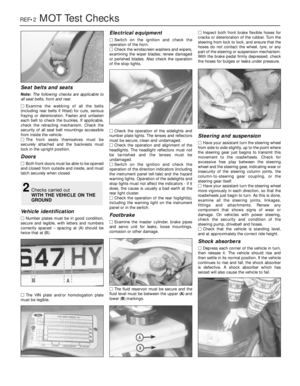 285
285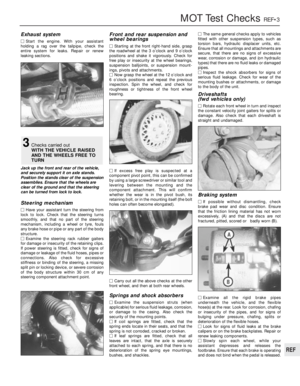 286
286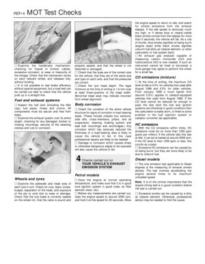 287
287 288
288 289
289 290
290 291
291 292
292 293
293 294
294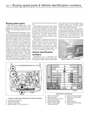 295
295 296
296 297
297 298
298 299
299 300
300 301
301 302
302
Fig. 1.3 Longitudinal section of 1116 cc and 1301 cc engines
(Sec 1)
Fig. 1.2 Cross-section of 903 cc engine (Sec 1")