Page 89 of 303
.
3Raise the rear roadwheels and check that
they turn freely when the handbrake lever is
fully released.
17 Handbrake cable-
ren")
locknut and turn the adjuster nut on the
handbrake primary rod (photo).
3Raise the rear roadwheels and check that
they turn freely when the handbrake lever is
fully released.
17 Handbrake cable-
renewal
1
1There are two cables, either of which may
be renewed independently
2Disconnect the cable, which is to be renewed,
from the shoe lever at the brake backplate.
3Disconnect the longer cable from the
primary link or rod and release the cable from
its retainers. On later models with a plastic
fuel tank, a cable bracket is moulded into the
side of the tank (photo).4Disconnect the shorter cable from the pivot
lever at the pulley on the rear axle (photo).
5Refit the new cables by reversing the
removal operations and then adjust as
described in the preceding Section.
18 Brake pedal-
removal and refitting
1
1The operations are described in
conjunction with the clutch pedal in Chapter
5, Section 4.
2The brake pedal pushrod will slide out of
the servo unit as the pedal is withdrawn.
19 Stop lamp switch
1
1The brake stop lamp switch is of plunger
type acting on the pedal arm.
2Adjust the position of the switch by turning
the locknuts until the stop lamps illuminate
when the pedal arm is depressed through 1.0
mm (0.039 in).
Braking system 8•9
Fig. 8.13 Handbrake components (Sec 17)
17.4 Handbrake cable pulley17.3 Handbrake cable guide on fuel tank
8
Fault finding - braking system
Excessive pedal travel
m mPads or shoes excessively worn
m mIncorrect pedal or servo pushrod adjustment
m mAutomatic adjusters faulty
m mSeized wheel cylinder or caliper piston
m mMaster cylinder seals worn
Pedal feels spongy or soggy
m
mAir in hydraulic system
m mLow fluid level
m mLoose connections
m mFlexible hose perished
m mDefective wheel cylinder or caliper seal
Pedal feels springy
m
mNew pads or linings not bedded-in
m mMaster cylinder mounting loose
Pedal vibrates when brakes applied
m
mDiscs or drums distorted
m mFriction linings excessively worn
m mLoose backplate or caliper mounting bolts
m mWear in steering or suspension components
Excessive effort required to stop car
m
mWorn or contaminated linings or pads
m mIncorrect grade of lining or pad material
m mServo vacuum hose leaking or disconnected
m mFaulty servo or non-return valve (55 or 70 models)
m mSeized caliper or wheel cylinder piston
m mOne circuit defective on dual circuit hydraulic system
Brakes pull to one side
m
mFriction linings contaminated on one side of car
m mSeized hydraulic piston on one side of car
m mDifferent types of linings fitted on different sides of car, or new
linings on one side only
m mSeized automatic adjuster on one side of car
Brakes drag
m
mHandbrake linkage overadjusted or seized
m mSeized caliper or wheel cylinder piston
Brakes squeal
m
mDrums or discs rusty or damp (temporary fault - no action
necessary)
m mDust or grit in brake drums
m mLinings excessively worn
Page 90 of 303

9System type . . . . . . . . . . . . . . . . . . . . . . . . . . . . . . . . . . . . . . . . . . . 12 negative earth, battery alternator and pre-engaged starter
Battery
Except 70S . . . . . . . . . . . . . . . . . . . . . . . . . . . . . . . . . . . . . . . . . . . . . . . 30 Ah
70S . . . . . . . . . . . . . . . . . . . . . . . . . . . . . . . . . . . . . . . . . . . . . . . . . . . . 40 Ah
Alternator
Type . . . . . . . . . . . . . . . . . . . . . . . . . . . . . . . . . . . . . . . . . . . . . . . . . . . . Marelli, Valeo or Bosch 45A, 55A or 65A, with integral voltage
regulator
Nominal voltage . . . . . . . . . . . . . . . . . . . . . . . . . . . . . . . . . . . . . . . . . . . 14 V
Minimum brush (wear) length . . . . . . . . . . . . . . . . . . . . . . . . . . . . . . . . . 6.0 mm (0.236 in)
Starter motor
Type . . . . . . . . . . . . . . . . . . . . . . . . . . . . . . . . . . . . . . . . . . . . . . . . . . . . Marelli, Bosch or Femsa pre-engaged
Nominal power . . . . . . . . . . . . . . . . . . . . . . . . . . . . . . . . . . . . . . . . . . . . 0.8 kW or 1.0 kW
Armature shaft endfloat . . . . . . . . . . . . . . . . . . . . . . . . . . . . . . . . . . . . . 0.1 to 0.5 mm (0.0039 to 0.0197 in)
Minimum brush (wear) length . . . . . . . . . . . . . . . . . . . . . . . . . . . . . . . . . 10.0 mm (0.39 in)
Wiper blades
Front . . . . . . . . . . . . . . . . . . . . . . . . . . . . . . . . . . . . . . . . . . . . . . . . . . . . Champion X-4801 (19 in) or X-4503 (18 in)
Rear . . . . . . . . . . . . . . . . . . . . . . . . . . . . . . . . . . . . . . . . . . . . . . . . . . . . Champion X-3303
Chapter 9 Electrical system
For modifications, and information applicable to later models, see Supplement at end of manual
Alternator - maintenance and precautions . . . . . . . . . . . . . . . . . . . . 3
Alternator - overhaul . . . . . . . . . . . . . . . . . . . . . . . . . . . . . . . . . . . . . 5
Alternator - removal and refitting . . . . . . . . . . . . . . . . . . . . . . . . . . . 4
Battery - inspection, charging, removal and refitting . . . . . . . . . . . . 2
Central door locking system . . . . . . . . . . . . . . . . . . . . . . . . . . . . . . . 32
Check control (warning module) system . . . . . . . . . . . . . . . . . . . . . . 34
Cigar lighter . . . . . . . . . . . . . . . . . . . . . . . . . . . . . . . . . . . . . . . . . . . . 36
Clocks - setting . . . . . . . . . . . . . . . . . . . . . . . . . . . . . . . . . . . . . . . . . 35
Courtesy lamp switch . . . . . . . . . . . . . . . . . . . . . . . . . . . . . . . . . . . . 12
Economy gauge (Econometer) . . . . . . . . . . . . . . . . . . . . . . . . . . . . . 33
Electrically-operated front door windows . . . . . . . . . . . . . . . . . . . . . 31
Exterior lamps - bulb renewal . . . . . . . . . . . . . . . . . . . . . . . . . . . . . . 19
Fault finding - electrical system . . . . . . . . . . . . . . See end of Chapter
Fuses and relays . . . . . . . . . . . . . . . . . . . . . . . . . . . . . . . . . . . . . . . . 10
General description . . . . . . . . . . . . . . . . . . . . . . . . . . . . . . . . . . . . . . 1
Headlamp - removal and refitting . . . . . . . . . . . . . . . . . . . . . . . . . . . 18
Headlamp beam - alignment . . . . . . . . . . . . . . . . . . . . . . . . . . . . . . . 17
Headlamp bulb - renewal . . . . . . . . . . . . . . . . . . . . . . . . . . . . . . . . . 16
Heated tailgate window - precautions and repair . . . . . . . . . . . . . . . 29Horns . . . . . . . . . . . . . . . . . . . . . . . . . . . . . . . . . . . . . . . . . . . . . . . . . 15
Instrument panel - dismantling . . . . . . . . . . . . . . . . . . . . . . . . . . . . . 22
Instrument panel - removal and refitting . . . . . . . . . . . . . . . . . . . . . . 21
Interior lamps - bulb renewal . . . . . . . . . . . . . . . . . . . . . . . . . . . . . . 20
Radio/cassette - fitting . . . . . . . . . . . . . . . . . . . . . . . . . . . . . . . . . . . 30
Rocker and push-button switches . . . . . . . . . . . . . . . . . . . . . . . . . . 13
Speedometer drive cable - renewal . . . . . . . . . . . . . . . . . . . . . . . . . 23
Starter motor - description and testing . . . . . . . . . . . . . . . . . . . . . . . 7
Starter motor - overhaul . . . . . . . . . . . . . . . . . . . . . . . . . . . . . . . . . . 9
Starter motor - removal and refitting . . . . . . . . . . . . . . . . . . . . . . . . . 8
Steering column combination switch . . . . . . . . . . . . . . . . . . . . . . . . 11
Tailgate contacts . . . . . . . . . . . . . . . . . . . . . . . . . . . . . . . . . . . . . . . . 14
Tailgate wiper blade and arm - removal and refitting . . . . . . . . . . . . 26
Tailgate wiper motor - removal and refitting . . . . . . . . . . . . . . . . . . . 27
Voltage regulator . . . . . . . . . . . . . . . . . . . . . . . . . . . . . . . . . . . . . . . . 6
Washer system . . . . . . . . . . . . . . . . . . . . . . . . . . . . . . . . . . . . . . . . . 28
Windscreen wiper blade and arm - removal and refitting . . . . . . . . . 24
Windscreen wiper motor - removal and refitting . . . . . . . . . . . . . . . . 25
9•1
Specifications Contents
Easy,suitable for
novice with little
experienceFairly easy,suitable
for beginner with
some experienceFairly difficult,
suitable for competent
DIY mechanic
Difficult,suitable for
experienced DIY
mechanicVery difficult,
suitable for expert DIY
or professional
Degrees of difficulty
54321
Page 91 of 303

1 General description
The electrical system is of 12 volt negative
earth type and employs a belt-driven
alternator and a pre-engaged type starter
motor.
The models in the range are all adequately
equipped with electrical accessories, while SX
versions also have power windows and
centralised door locking plus a check control
system (Section 34).
2 Battery- inspection, charging,
removal and refitting
2
1The battery is of maintenance-free type and
under normal circumstances, no topping up
will be required, but regularly check that the
electrolyte level is between the minimum and
maximum lines on the translucent battery
casing.
2If the electrolyte level does drop below theminimum line, suspect a leak in the battery
casing or that the alternator is overcharging. If
the latter is the case, rectify the alternator fault
and then prise out the two rectangular plugs
from the top of the battery and top up with
distilled or purified water.
3Always keep the battery terminals clean
and smear them with petroleum jelly to
prevent corrosion.
4The battery will normally be kept fully
charged by the alternator, but it is possible for
the battery to become discharged if the daily
mileage is very low with much use being
made of the starter and electrical accessories.
5When the battery begins to deteriorate with
age it may also require a boost from a mains
charger.
6Disconnect both battery leads before
connecting the mains charger. 7To remove the battery from the car, first
disconnect the leads from the battery
terminals (earth first) and then unscrew the
securing clamp from the casing projection at
the base of the casing (photo).
8Lift the battery from its mounting platform.
Refitting is a reversal of removal. Reconnect
the earth cable last.
Fuses
Circuit protected Fuse rating (A)
1 Stop lamps, direction indicator lamps, instrument panel warning
lamps, tachometer economy gauge, check control system . . . . . . 10
2 Windscreen wiper and washer, rear screen wiper/washer, check
system panel illumination . . . . . . . . . . . . . . . . . . . . . . . . . . . . . . . . 20
3 Left front parking, right rear tail lamp, cigar lighter illumination,
heater control and clock, digital clock illumination . . . . . . . . . . . . . 7.5
4 Right front parking lamp and left rear tail lamp, instrument panel
illumination and rear number plate lamp . . . . . . . . . . . . . . . . . . . . . 7.5
5 Left-hand dipped headlamp, rear foglamps . . . . . . . . . . . . . . . . . . 10
6 Right-hand dipped headlamp . . . . . . . . . . . . . . . . . . . . . . . . . . . . . 10
7 Left-hand headlamp (main beam) . . . . . . . . . . . . . . . . . . . . . . . . . . 10
8 Right-hand headlamp (main beam) . . . . . . . . . . . . . . . . . . . . . . . . . 10
9 Engine cooling fan and horn (Comfort) . . . . . . . . . . . . . . . . . . . . . . 25
10 Heater booster fan, digital clock map reading lamp . . . . . . . . . . . . 20
11 Heated tailgate glass . . . . . . . . . . . . . . . . . . . . . . . . . . . . . . . . . . . 20
12 Courtesy lamps, cigar lighter, radio power feed, disc pad
sensors, economy gauge (ES models) . . . . . . . . . . . . . . . . . . . . . . 10
13 Hazard warning lamps . . . . . . . . . . . . . . . . . . . . . . . . . . . . . . . . . . 10
14 Spare (Comfort), Horn (Super) . . . . . . . . . . . . . . . . . . . . . . . . . . . . 20
BulbsWattage
Headlamp . . . . . . . . . . . . . . . . . . . . . . . . . . . . . . . . . . . . . . . . . . . . . . . . 40/45 or Halogen H4 60/55
Front parking . . . . . . . . . . . . . . . . . . . . . . . . . . . . . . . . . . . . . . . . . . . . . 5
Side repeater . . . . . . . . . . . . . . . . . . . . . . . . . . . . . . . . . . . . . . . . . . . . . 5
Tail . . . . . . . . . . . . . . . . . . . . . . . . . . . . . . . . . . . . . . . . . . . . . . . . . . . . 5
Stop . . . . . . . . . . . . . . . . . . . . . . . . . . . . . . . . . . . . . . . . . . . . . . . . . . . . 21
Reversing . . . . . . . . . . . . . . . . . . . . . . . . . . . . . . . . . . . . . . . . . . . . . . . . 21
Rear foglamp . . . . . . . . . . . . . . . . . . . . . . . . . . . . . . . . . . . . . . . . . . . . . 21
Direction indicator . . . . . . . . . . . . . . . . . . . . . . . . . . . . . . . . . . . . . . . . . 21
Rear number plate . . . . . . . . . . . . . . . . . . . . . . . . . . . . . . . . . . . . . . . . . 5
Courtesy lamp (roof) . . . . . . . . . . . . . . . . . . . . . . . . . . . . . . . . . . . . . . . . 10
Courtesy lamp (pillar) . . . . . . . . . . . . . . . . . . . . . . . . . . . . . . . . . . . . . . . 5
Warning and indicator . . . . . . . . . . . . . . . . . . . . . . . . . . . . . . . . . . . . . . Wedge base
Torque wrench settingsNm lbf ft
Alternator mounting and adjustment nuts . . . . . . . . . . . . . . . . . . . . . . . 50 87
Starter motor bolts . . . . . . . . . . . . . . . . . . . . . . . . . . . . . . . . . . . . . . . . . 48 35
9•2 Electrical system
2.7 Battery clamp
If battery terminal corrosion
has occurred, it may be
neutralised by applying
sodium bicarbonate or
household ammonia.
Page 92 of 303

3 Alternator-
maintenance and precautions
1
To avoid damage to the alternator, the
following precautions should be observed.
1Disconnect the leads from the battery
before connecting a mains charger to the
battery terminals.
2Never stop the engine by pulling off one of
the battery leads.
3Disconnect the battery if electric welding is
to be carried out on the vehicle.
4If using booster cables from another battery
to start the car, make sure that they are
connected positive to positive and negative to
negative.
5Maintenance consists of keeping the
outside of the alternator clean, the electrical
connections secure and the drivebelt correctly
tensioned, see Chapter 2, Section 8.
4 Alternator-
removal and refitting
1
Note: Depending on the model, access to the
alternator from above may be poor in which
case it will be necessary to work from the
underside of the vehicle, through the
right-hand wheel arch (after removing the
roadwheel and the lower undershield). Refer
to Chapter 13 for details.
1Disconnect the leads from the rear of the
alternator.2Release the mounting and adjuster link nuts
and push the alternator as far as it will go in
towards the engine (photos).
3Slip the drivebelt from the pulley.
4Remove the mounting and adjuster bolts
and lift the alternator from the brackets on the
engine. Remove downwards on 1116 cc and
1301 cc models.
5Refitting is a reversal of removal, tension
the drivebelt as described in Chapter 2,
Section 8.
5 Alternator- overhaul
3
1Overhaul of the alternator should be limited
to renewal of the brushes. If the unit has
covered a high mileage, it will be found moreeconomical to exchange it for a new or
factory-reconditioned one, rather than renew
worn components on the original unit.
Brush renewal
(Marelli alternator)
2Unscrew the nuts and take off the rear cover.
3Unscrew the two small bolts and withdraw
the brush holder (photos).
4Fit the new brush holder which is supplied
complete with brushes, by reversing the
removal operations.
Brush renewal
(Bosch alternator)
5Where applicable, remove the radio
suppression condenser (capacitor) from the
rear end frame (one screw and washer, and a
plug-in connection).
6Undo the two screws which retain the brush
holder to the rear frame of the alternator, then
Electrical system 9•3
5.3A Alternator brush holder bolt4.2B Alternator adjuster bolt4.2A Alternator mounting
Fig. 9.1 Exploded view of typical alternator (Sec 5)
1 Pulley
2 Fan
3 Bolts
4 Washers
5 Drive-end bracket
6 Stator windings
7 Plate screw
8 Diode plate
(rectifier pack)9 Body
10 Brush
11 Spring
12 Brush holder
13 Condenser
14 Screws and
washers
15 Screws and
washers16 Screws and
washers
17 Plug socket
18 Suppressor
19 Shaft nut
20 Spring washer
21 Thrust ring
22 Bearing
23 Retainer plate24 Thrust ring
25 Spring washer
26 Screw and washer
27 Key
28 Rotor
29 Bearing
30 Backing washer
31 Shield (where
applicable)
5.3B Removing alternator brush holder
9
Page 93 of 303

ease the holder out of the alternator. Inspect
the brushes and if worn below the specified
minimum length, they must be renewed.
7Disconnect the brush leads by unsoldering
or carefully cutting them.
8When soldering the new brush leads, do
not allow solder to run down them or their
flexibility will be ruined.
9When inspecting or renewing brushes,
check the surface of the slip rings. Clean them
with solvent or if they are very discoloured,
use very fine glasspaper.
6 Voltage regulator
1This is of integral type and is part of the
brushholder assembly.
2No provision is made for adjustment or
overhaul.
7 Starter motor-
description and testing
2
1The starter motor may be one of two
different makes. Both are of pre-engaged
type.
2This type of starter motor incorporates a
solenoid mounted on top of the starter motor
body. When the ignition switch is operated,
the solenoid moves the starter drive pinion,
through the medium of the shift lever, into
engagement with the flywheel starter ring
gear. As the solenoid reaches the end of its
stroke, and with the pinion by now partially
engaged with the flywheel ring gear, the main
fixed and moving contacts close and engage
the starter motor to rotate the engine.
3This pre-engagement of the starter drive
does much to reduce the wear on the flywheel
ring gear associated with inertia type starter
motors.
4If the starter fails, some fault-finding can be
done with it still on the car. Check the ignition
warning light comes on, and does not go out
when the starter is switched on. If it goes out,
the fault is probably in the battery. If it stays
bright, get an assistant to work the switch,whilst listening to the starter. Listen to find out
if the solenoid clicks into position. If it does
not, pull off the solenoid wire, and check it
with a test bulb. If the wire is live when the key
is turned, but the solenoid does not move,
take off the starter and remove it to the bench
for overhaul.
8 Starter motor-
removal and refitting
1
1Disconnect the battery negative lead.
2Disconnect the lead from the starter motor
(photo).
3Unscrew the fixing bolts and withdraw the
starter motor, downwards on 1116 cc and
1301 cc models (photo).
4Refitting is a reversal of the removal
procedure.
9 Starter motor- overhaul
3
1As with the alternator, the operations
should normally be limited to renewal of the
brushes. If the unit has covered a high
mileage it will usually be more economical to
purchase a new or factory-reconditioned one
rather than renew several components of the
original unit.
2Owing to the possibility that a fault can
develop in the starter motor solenoid or drive
assembly, full dismantling procedures are
given later in this Section.
Brush - renewal
3Slide off the cover band.
4Using a hooked piece of wire, pull up the
springs so that the brushes can be withdrawn
and their lengths checked for wear. If they
have worn below the specified minimum
length, renew them by extracting the brush
lead connecting screws (photo).
Solenoid
5Disconnect the field connecting wire from
the solenoid.
6Unscrew the bolts which hold the solenoid
to the end-frame.
7Unscrew the yoke tie-rod nuts.
9•4 Electrical system
9.4 Starter motor brush partly withdrawn
8.2 Starter motor connections8.3 Removing starter motor
Fig. 9.2 Exploded view of typical starter motor (Sec 9)
1 Armature
2 Drive pinion/clutch3 Drive end bracket
4 Shift lever5 Solenoid
6 Brush endplate7 Brush
8 Field windings
Gripping the brush leads with
a pair of pliers to act as a
heat sink will prevent heat
transfer to the internal
components of the alternator.
Page 94 of 303
.
9Extract the split pin and tap out the
e")
8Withdraw the solenoid and yoke off the
armature and from the drive end bracket.
Note the steel and fibre washers and the
shims on the armature shaft (photo).
9Extract the split pin and tap out the
engagement lever pivot pin.
10Pull the rubber packing piece from the
drive end bracket.
11Withdraw the armature with solenoid
plunger, coil spring and engagement lever.
12Clean the commutator with a fuel soaked
rag or very fine glass paper. Do not undercut
the mica insulators on the commutator.
Drive
13To remove the drive assembly from the
armature shaft, use a piece of tubing to tap
the stop collar down the shaft to expose the
snap ring. Remove the snap ring and stop
collar and slide the drive assembly from the
shaft.
14Refitting is a reversal of removal, but use a
new snap ring to secure the drive to the
armature shaft.
10 Fuses and relays
1
1The fuse box is located under the left-hand
side of the facia panel and is held in place by
two hand screws (photo).2The fuses and the circuits protected are
identified by symbols. Refer also to Specifi-
cations.
3If a fuse blows, always renew it with one of
identical rating. If the new fuse blows
immediately, find the cause before renewing
the fuse for the second time. This is usually
due to defective wiring insulation causing a
short circuit.
4Never substitute a piece of wire or other
makeshift device for a proper fuse.
5Various relays are plugged into the fuse
block and include those for the heated rear
screen, heater and horns.
6On cars fitted with power-operated front
windows and centralised door locking, the
fuses and relays for these circuits are
mounted separately under the right-hand side
of the facia panel.
7The relay (flasher unit) for the direction
indicators and hazard warning lamps is
located on the lower part of the
steering column combination switch and
is accessible after removing the column
shroud.
11 Steering column
combination switch
1
1Disconnect the battery negative lead.
2Remove the steering column shrouds. 3The switch can be removed without
having to take off the steering wheel, but for
clarity, the photographs show the wheel
removed.
4Unscrew the switch clamp nuts, disconnect
the wiring plug and remove the switch from
the steering column (photo).
5Refitting is a reversal of removal, but make
sure that the activating projections on the
steering wheel hub engage correctly with the
switches.
12 Courtesy lamp switch
1
1These are located in and secured to the
body pillars with a single screw (photo).
2Disconnect the battery negative lead.
3Extract the switch screw and withdraw the
switch.
4If the leads are to be disconnected, tape
them to the pillar to prevent them from
slipping inside.
5Refitting is a reversal of removal. Apply
petroleum jelly to the switch contacts to
prevent corrosion.
13 Rocker and push-button
switches
1
1These are mounted in panels on each side
of the instrument panel.
2Disconnect the battery negative lead.
3Prise off the instrument panel hood cover.
This is held in place by clips. The careful use
of a screwdriver will assist in releasing them
(see Section 21).
4Extract the switch panel fixing screws.
These compress spring clips which in turn
secure the switch panel (photo).
5Withdraw the switch panel until the wiring
plugs can be disconnected. Record the
location of the plugs before disconnecting
Electrical system 9•5
11.4 Unscrewing steering column switch
clamp nut
1 Direction indicator flasher unit (relay)10.1 Fuse block (later models)
1 Horn relay
2 Heated tailgate window relay9.8 Starter motor dismantled
13.4 Switch panel screw12.1 Courtesy lamp switch
9
Page 95 of 303
.
6A push-button switch can be removed by
compressing its retaining tabs and pushing it
from the panel.
7A rocker switch can be removed if its")
them. Carefully release the fibre optic
filaments (photos).
6A push-button switch can be removed by
compressing its retaining tabs and pushing it
from the panel.
7A rocker switch can be removed if its knob
is pulled off and the switch sections
withdrawn from the panel.
8Reassembly and refitting of both types of
switches are reversals of removal and
dismantling.
14 Tailgate contacts
1
1Contact blocks are used to transmit power
to the heated tailgate window and to the wiper
motor.
2The block on the tailgate or the body may
be released by prising their ends with a
screwdriver (photos).
15 Horns
1
1These are mounted close to the
engine/transmission left-hand mounting
below the radiator.
2Apart from keeping the connecting leads
secure, no maintenance or adjustment is
required.
16 Headlamp bulb- renewal
1
1Open the bonnet and pull off the plug and
the rubber cover from the rear of the
headlamp (photo).
2Prise back the spring bulbholder clips and
withdraw the combined bulb and holder
(photos).
3Refit the new bulb. Avoid fingering it if it is
of halogen type. Should the fingers touch the
bulb, wipe it with a rag soaked in methylated
spirit to remove any residual grease.
4Turn the bulbholder until the pip on its
flange engages in the cut-out in the rim of the
reflector.
5Snap back the spring retaining clips, refit
the rubber cover and reconnect the plug.
17 Headlamp beam- alignment
2
1It is recommended that the headlamp
beams are aligned by your dealer or a service
station having optical setting equipment.
2Where an owner wishes to do the job
himself, proceed in the following way.
3Have the car standing on a level floor with
9•6 Electrical system
Fig. 9.3 Headlamp beam adjustment
screws (Sec 17)
A Vertical B Horizontal
16.2B Headlamp halogen type bulb16.2A Headlamp bulbholder spring
clips
14.2B Body contact block
16.1 Headlamp plug and rubber
cover
14.2A Tailgate contact block13.5B Switch panel fibre optic13.5A Withdrawing switch panel
Page 96 of 303
 from it.
4Mark the wall to correspond with the
centres of the headlamps.
5Switch to dipped beams when the brightes")
the tyres correctly inflated and square to a
wall, at a distance of 10.0 m (32.8 ft) from it.
4Mark the wall to correspond with the
centres of the headlamps.
5Switch to dipped beams when the brightest
parts of the light pattern should be below the
marks on the wall by an amount equal to one
tenth of the distance between the floor and
the mark on the wall.
6Adjust the beams as necessary by turning
the adjuster screws (A) vertical or (B) hori-
zontal, which are located at the rear of the
headlamp.
18 Headlamp-
removal and refitting
1
1Open the bonnet and extract the two
headlamp mounting screws from the top rail
(photo).
2Pull the headlamp unit forward off its
ballstud and then disconnect the wiring plug
(photo).
3Refitting is a reversal of removal.
19 Exterior lamps-
bulb renewal
1
Front parking lamp
1The bulbholder is located in the headlamp
reflector. 2Open the bonnet, push and twist the
bulbholder from its location (photo).
3The wedge base type bulb is simply pulled
from its holder.
Front direction indicator lamp
4Extract the screws and remove the lens
(photo).
5Depress and twist the bayonet fitting type
bulb from its holder.
Side repeater lamp
6This bulb may be renewed in one of two
ways. Either partially remove the underwing
protective shield and reach up under the front
wing and pull the holder out of the lamp body
or depress the lamp retaining tab and
withdraw the lamp from outside the wing. The
tab is very brittle (photo). 7Remove the bulb from the holder.
Rear lamp cluster
8Open the tailgate.
9Gently prise up the clips on the top surface of
the lens. Pull the upper part of the lens outwards
and release it from the lower fixings (photo).
10The individual lamp bulbs may be
renewed, all of them being of bayonet fitting
type (photo).
Rear number plate lamp
11Insert a screwdriver blade in the lens slot
and prise it from the bulb holder. Withdraw
the bulb.
12If preferred, the complete lamp may be
removed from the bumper by reaching up
under the bumper and squeezing the lamp
retaining tabs (photo).
Electrical system 9•7
19.2 Front parking lamp bulb18.2 Withdrawing headlamp18.1 Headlamp upper fixing screw
19.12 Rear number plate lamp withdrawn
19.10 Rear lamp bulbs
19.6 Side repeater lamp19.4 Front direction indicator lamp lens
and bulb
19.9 Rear lamp lens upper clip
9
A Direction indicator
B ReversingC Stop E Fog
D Tail
 1
1 2
2 3
3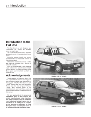 4
4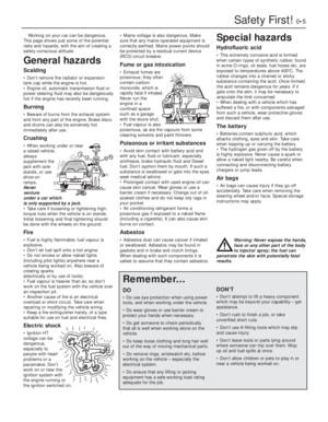 5
5 6
6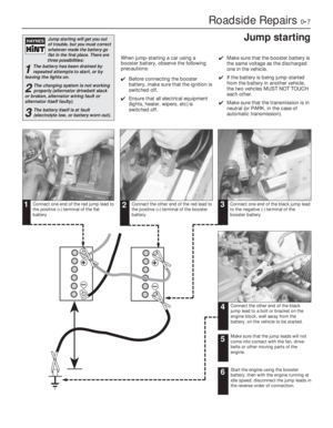 7
7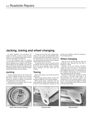 8
8 9
9 10
10 11
11 12
12 13
13 14
14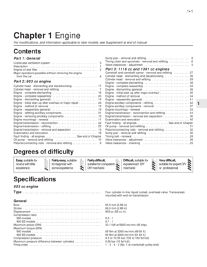 15
15 16
16 17
17 18
18 19
19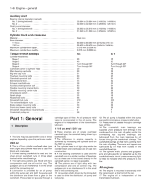 20
20 21
21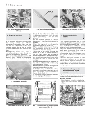 22
22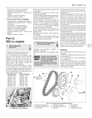 23
23 24
24 25
25 26
26 27
27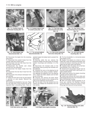 28
28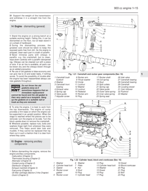 29
29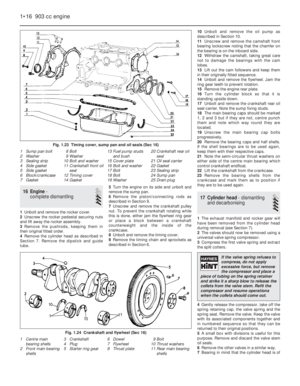 30
30 31
31 32
32 33
33 34
34 35
35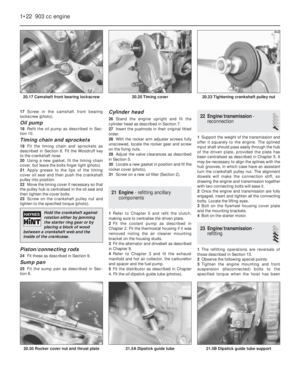 36
36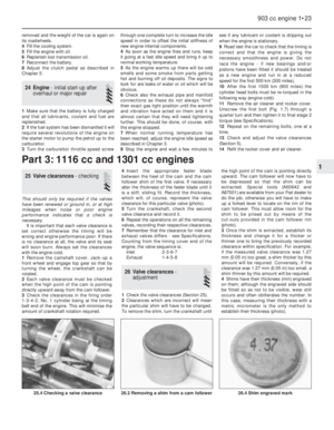 37
37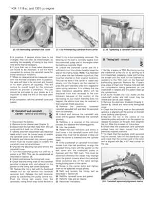 38
38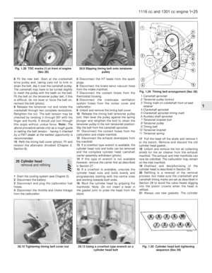 39
39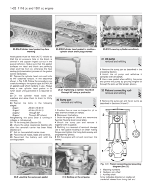 40
40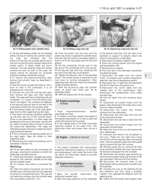 41
41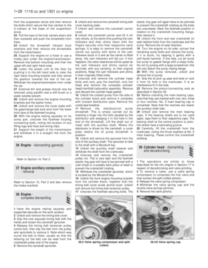 42
42 43
43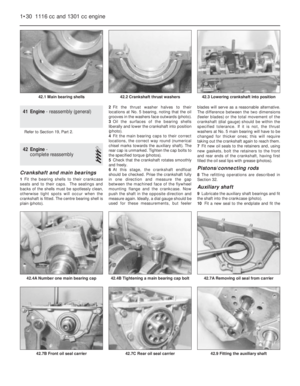 44
44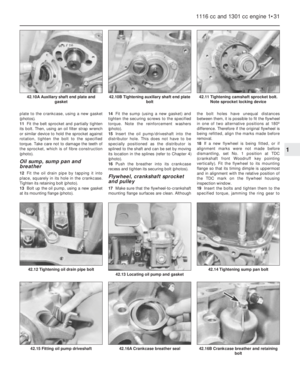 45
45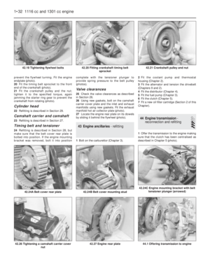 46
46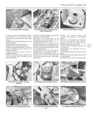 47
47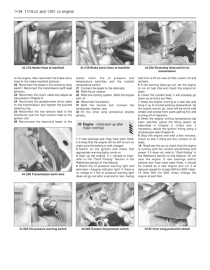 48
48 49
49 50
50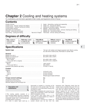 51
51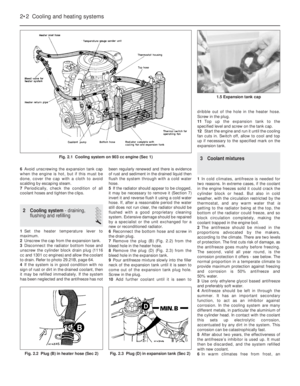 52
52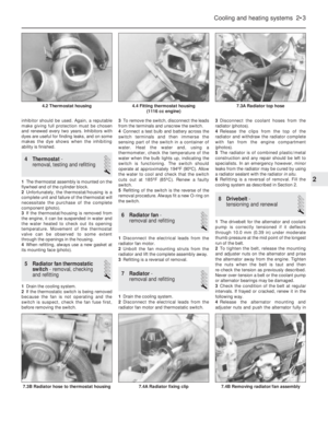 53
53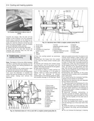 54
54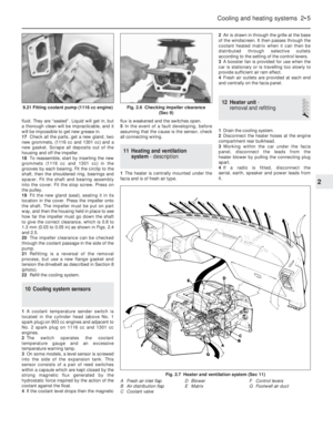 55
55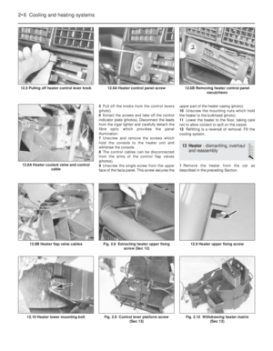 56
56 57
57 58
58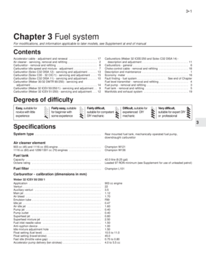 59
59 60
60 61
61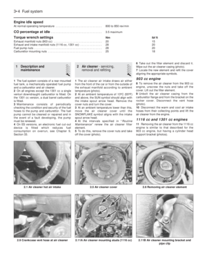 62
62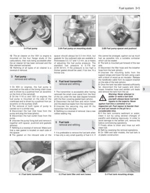 63
63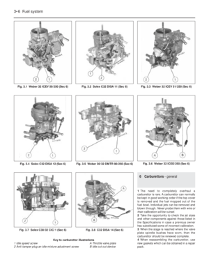 64
64 65
65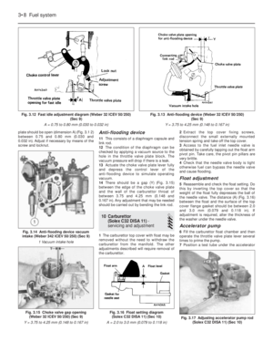 66
66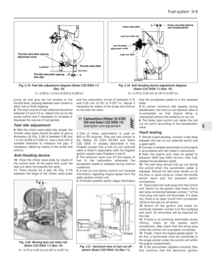 67
67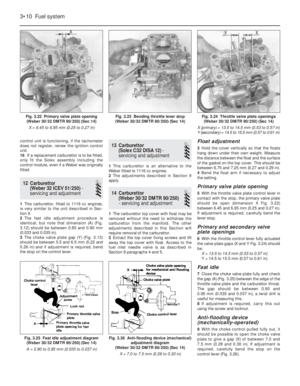 68
68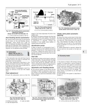 69
69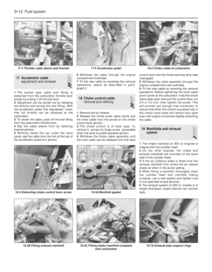 70
70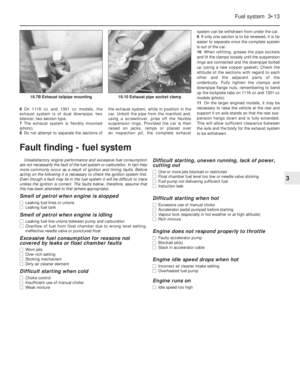 71
71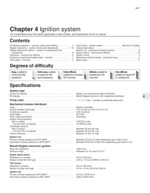 72
72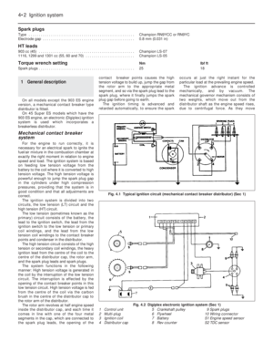 73
73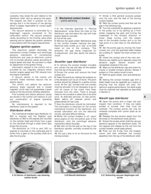 74
74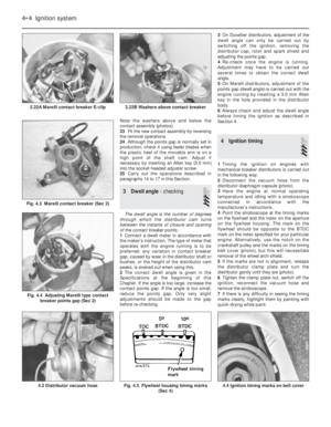 75
75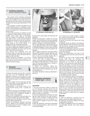 76
76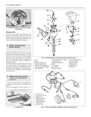 77
77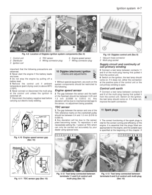 78
78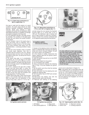 79
79 80
80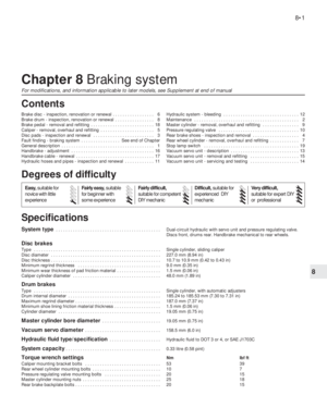 81
81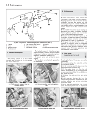 82
82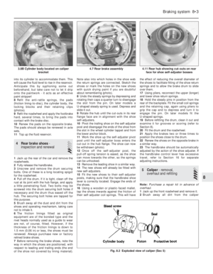 83
83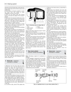 84
84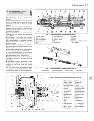 85
85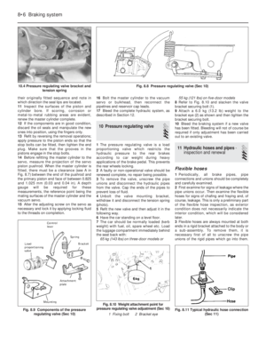 86
86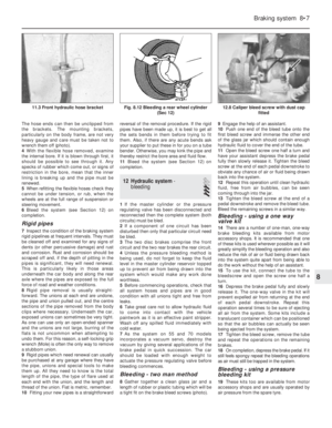 87
87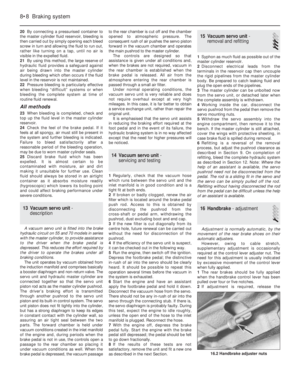 88
88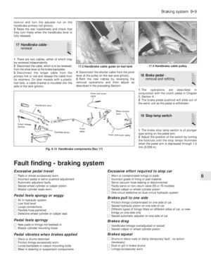 89
89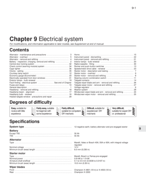 90
90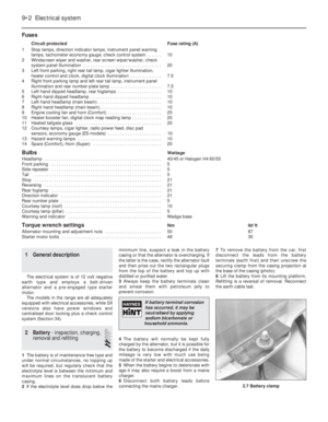 91
91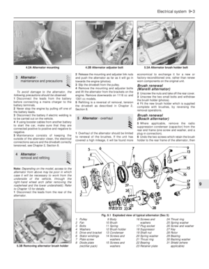 92
92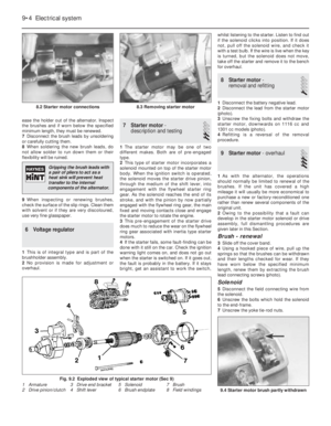 93
93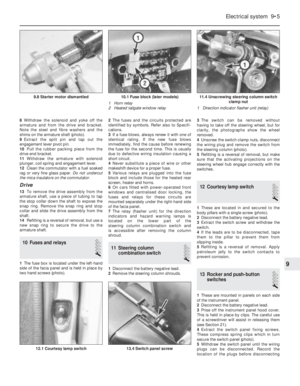 94
94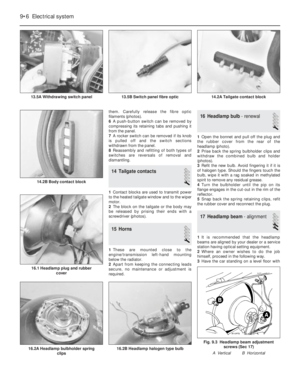 95
95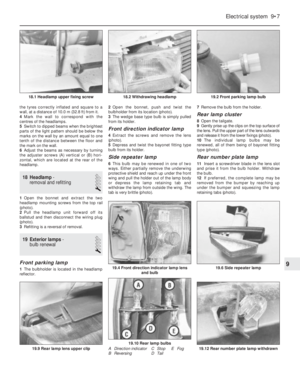 96
96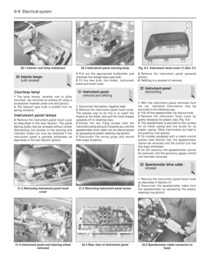 97
97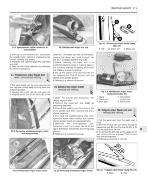 98
98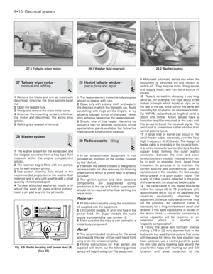 99
99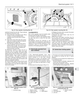 100
100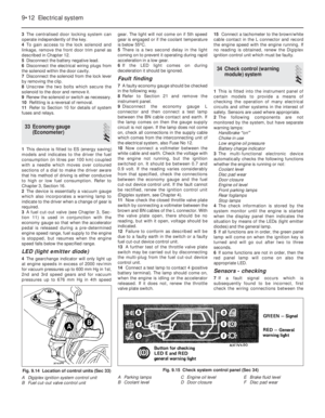 101
101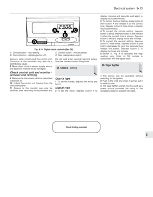 102
102 103
103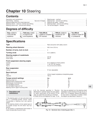 104
104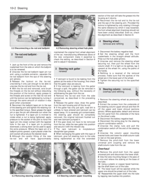 105
105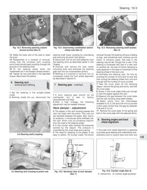 106
106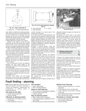 107
107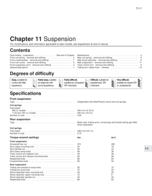 108
108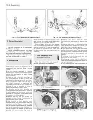 109
109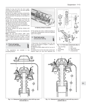 110
110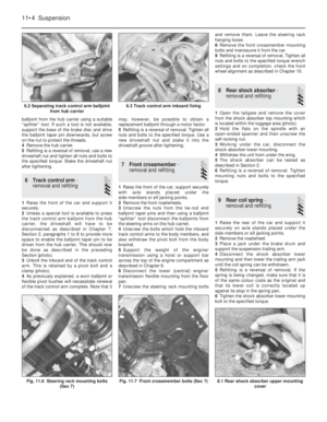 111
111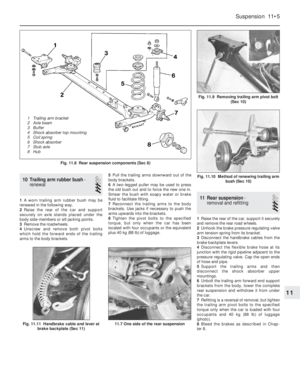 112
112 113
113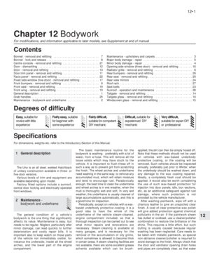 114
114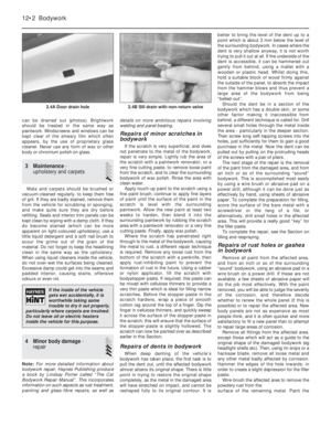 115
115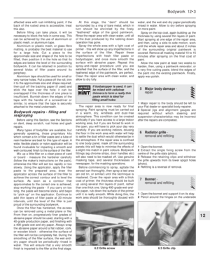 116
116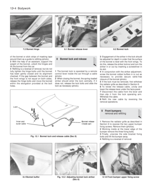 117
117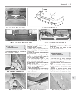 118
118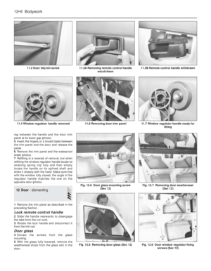 119
119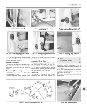 120
120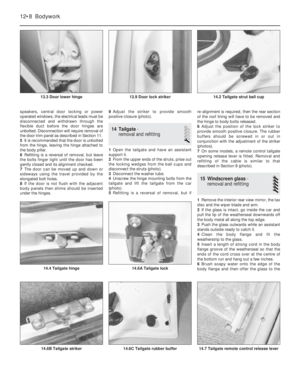 121
121 122
122 123
123 124
124 125
125 126
126 127
127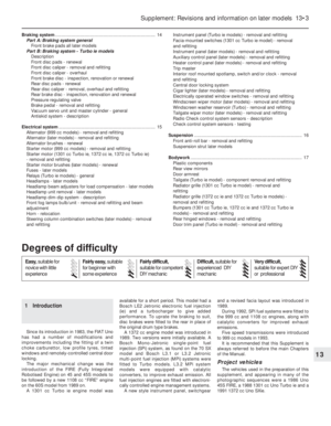 128
128 129
129 130
130 131
131 132
132 133
133 134
134 135
135 136
136 137
137 138
138 139
139 140
140 141
141 142
142 143
143 144
144 145
145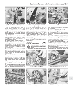 146
146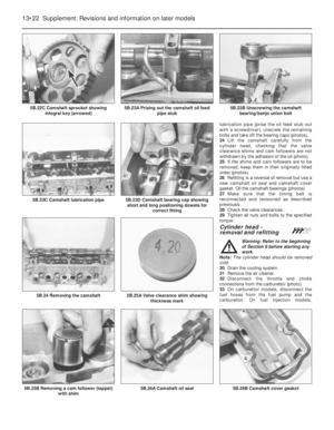 147
147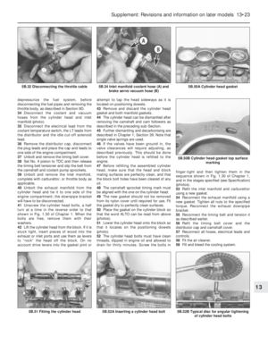 148
148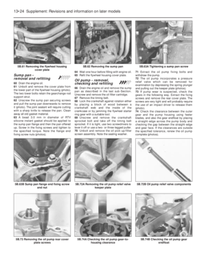 149
149 150
150 151
151 152
152 153
153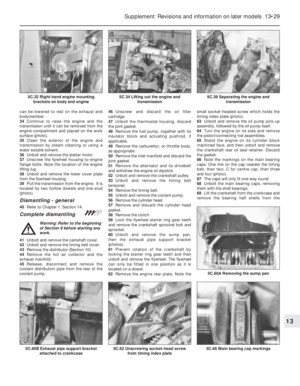 154
154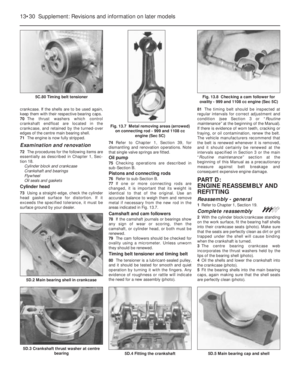 155
155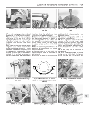 156
156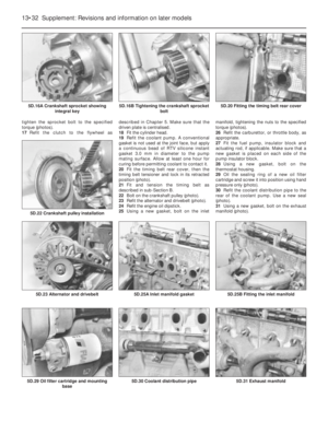 157
157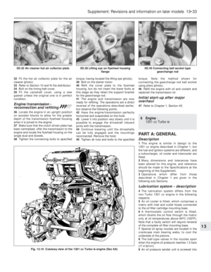 158
158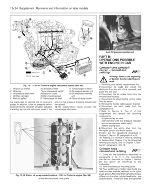 159
159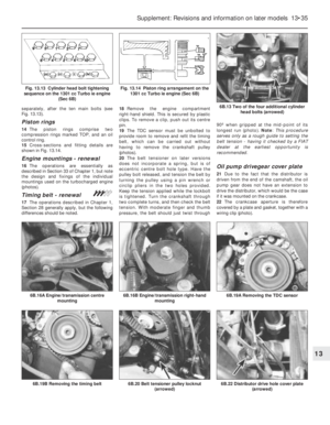 160
160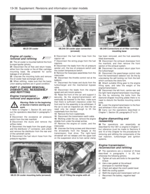 161
161 162
162 163
163 164
164 165
165 166
166 167
167 168
168 169
169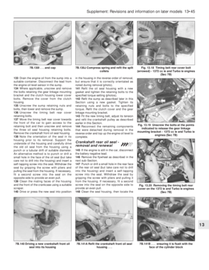 170
170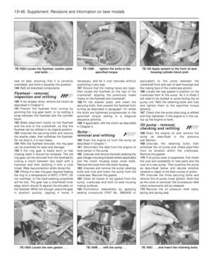 171
171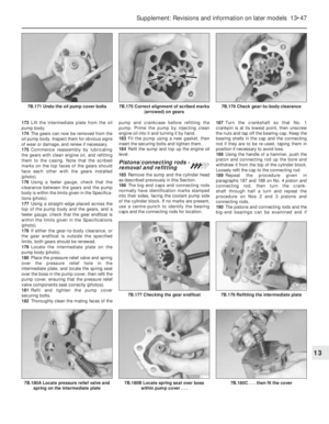 172
172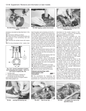 173
173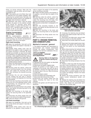 174
174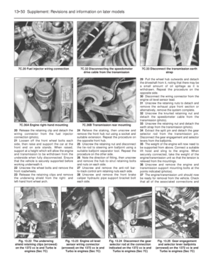 175
175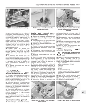 176
176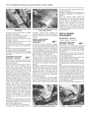 177
177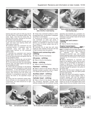 178
178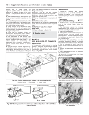 179
179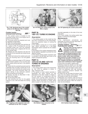 180
180 181
181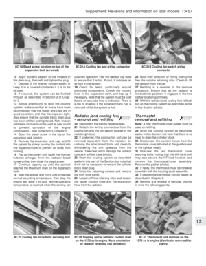 182
182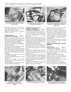 183
183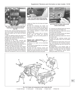 184
184 185
185 186
186 187
187 188
188 189
189 190
190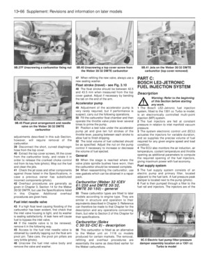 191
191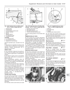 192
192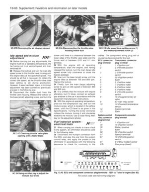 193
193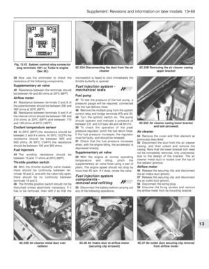 194
194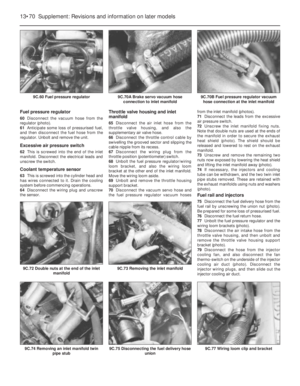 195
195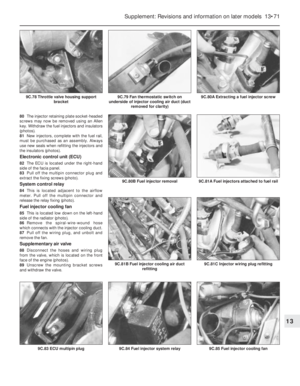 196
196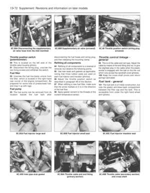 197
197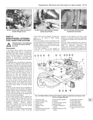 198
198 199
199 200
200 201
201 202
202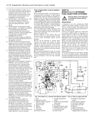 203
203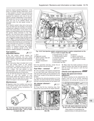 204
204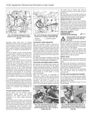 205
205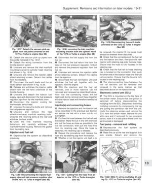 206
206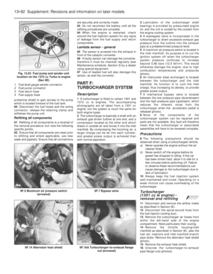 207
207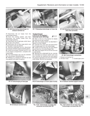 208
208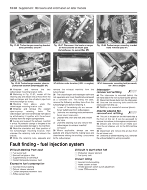 209
209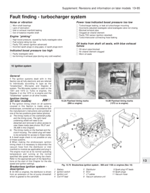 210
210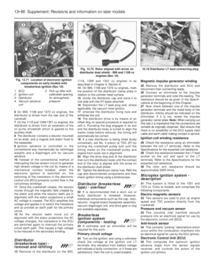 211
211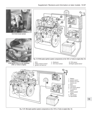 212
212 213
213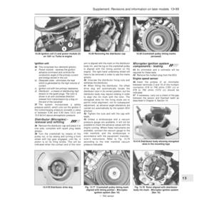 214
214 215
215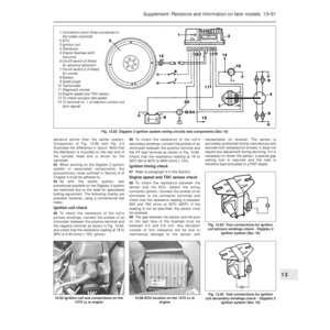 216
216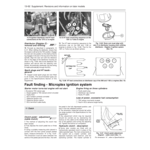 217
217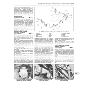 218
218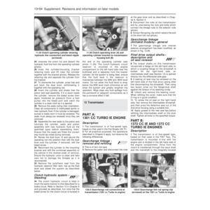 219
219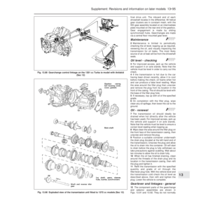 220
220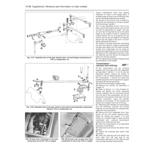 221
221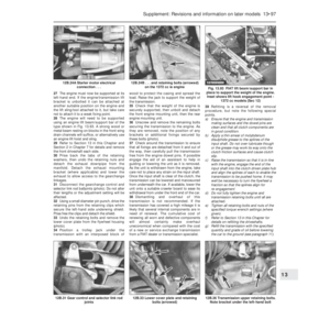 222
222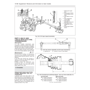 223
223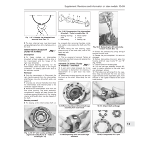 224
224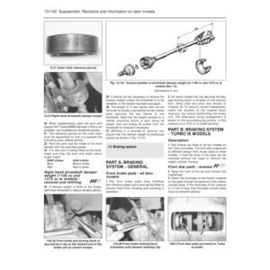 225
225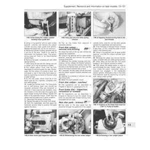 226
226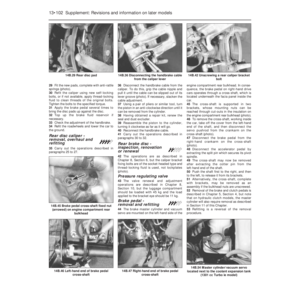 227
227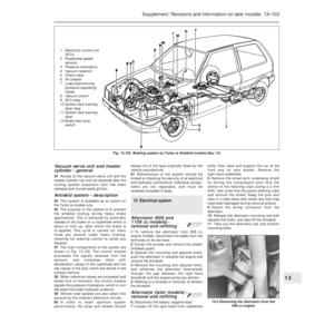 228
228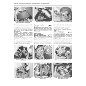 229
229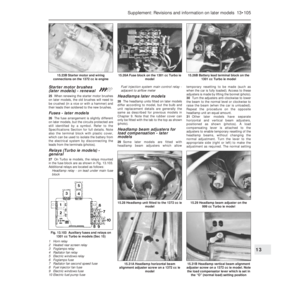 230
230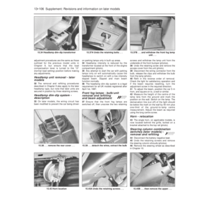 231
231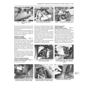 232
232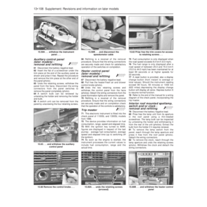 233
233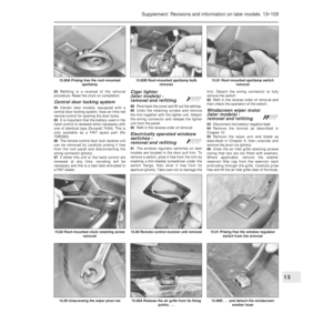 234
234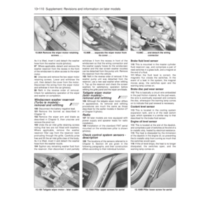 235
235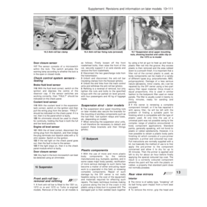 236
236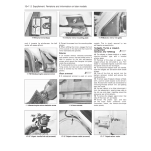 237
237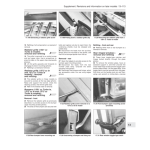 238
238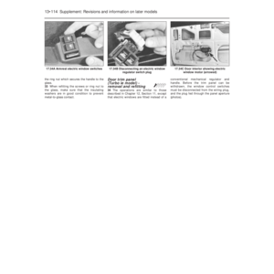 239
239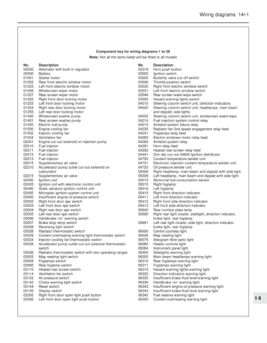 240
240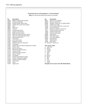 241
241 242
242 243
243 244
244 245
245 246
246 247
247 248
248 249
249 250
250 251
251 252
252 253
253 254
254 255
255 256
256 257
257 258
258 259
259 260
260 261
261 262
262 263
263 264
264 265
265 266
266 267
267 268
268 269
269 270
270 271
271 272
272 273
273 274
274 275
275 276
276 277
277 278
278 279
279 280
280 281
281 282
282 283
283 284
284 285
285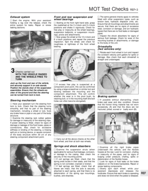 286
286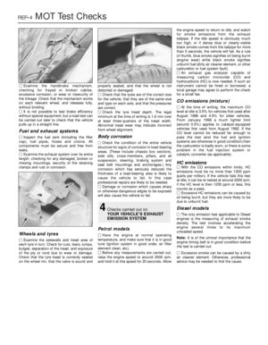 287
287 288
288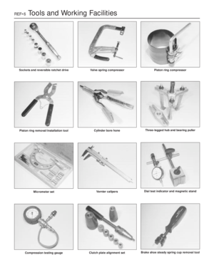 289
289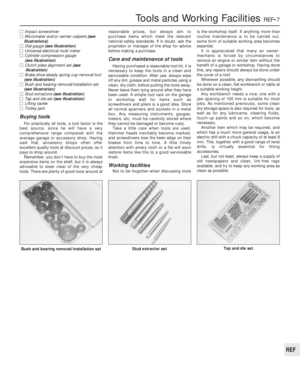 290
290 291
291 292
292 293
293 294
294 295
295 296
296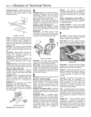 297
297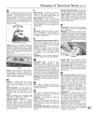 298
298 299
299 300
300 301
301 302
302