Page 97 of 303
.
2The festoon type bulb")
20 Interior lamps-
bulb renewal
1
Courtesy lamp
1The lamp lenses, whether roof or pillar
mounted, are removed by prising off using a
screwdriver inserted under one end (photo).
2The festoon type bulb is pulled from its
spring contacts.
Instrument panel lamps
3Remove the instrument panel hood cover
as described in the next Section. The panel
lighting bulbs may be renewed without further
dismantling, but access to the warning and
indicator bulbs can only be obtained if the
instrument panel is partially withdrawn as
described in the next Section (photo). 4Pull out the appropriate bulbholder and
withdraw the wedge base type bulb.
5Fit the new bulb, the holder, instrument
panel and hood cover.
21 Instrument panel-
removal and refitting
1
1Disconnect the battery negative lead.
2Remove the instrument panel hood cover.
The easiest way to do this is to insert the
fingers at the sides, and pull the hood sharply
upwards off its retaining clips.
3Extract the two fixing screws from the
instrument panel and pull it towards you until the
speedometer drive cable can be disconnected
by squeezing its plastic retaining ring (photo).
4Disconnect the wiring plugs and record
their exact locations. 5Remove the instrument panel upwards
(photo).
6Refitting is a reversal of removal.
22 Instrument panel-
dismantling
1
1With the instrument panel removed from
the car, individual instruments may be
removed in the following way.
2Pull off the speedometer trip device knob.
3Remove the instrument hood cover by
gently releasing the plastic clips (Fig. 9.4).
4The speedometer is secured by two screws
for its metal casing and one screw for its
plastic casing. Other instruments are held to
the panel by nuts (photo).
5On models equipped with a check control
system (see Section 34), the speedometer
cannot be removed until the control unit has
first been withdrawn.
6On ES versions, the speedometer cannot
be removed until the economy gauge control
unit has been removed.
23 Speedometer drive cable-
renewal
1
1Remove the instrument panel hood cover
as described in Section 21.
2Disconnect the speedometer cable from
the speedometer by squeezing the plastic
retaining ring (photo).
9•8 Electrical system
23.2 Speedometer cable connector at
head22.4 Rear view of instrument panel21.5 Instrument panel and steering wheel
removed
21.3 Removing instrument panel screw21.2 Removing instrument panel hood
cover
Fig. 9.4 Instrument hood cover (1) (Sec 21)20.3 Instrument panel warning lamp20.1 Interior roof lamp withdrawn
Page 98 of 303
.
4Withdraw the cable through the bulkhead
grommet.
5Refit the new cable assembly by re")
3Working at the transmission, disconnect
the speedometer cable by unscrewing the
knurled retaining ring (photo).
4Withdraw the cable through the bulkhead
grommet.
5Refit the new cable assembly by reversing
the removal operations.
24 Windscreen wiper blade and
arm- removal and refitting
1
1The wiper blade can be removed once the
arm has been pulled away from the glass and
locked in position.
2Depress the small tab (A) and push the
U-shaped carrier out of the hook (B) of thewiper arm. The blade can then be withdrawn,
passing the wiper arm hook through the
slot (C) in the blade stretcher (Fig. 9.5).
3Before removing the wiper arm, it is
worthwhile sticking a strip of masking tape on
the screen to indicate the setting of the arm
and blade as a guide to refitting.
4Flip up the plastic cover and unscrew the
arm retaining nut. Pull off the arm from the
splined drive spindle (photo).
5Refitting is a reversal of removal.25 Windscreen wiper motor-
removal and refitting
2
1Open the bonnet and disconnect the
battery negative lead.
2Remove the wiper arm and blade as
previously described.
3Prise off the sealing cover from around the
drive spindle and then unscrew the drive
spindle bezel nut.
4Pull back the weathersealing strip from
above the wiper motor location and remove
the two screws which are exposed (photo).
5Withdraw the motor/gearbox with
protective cover from under the lip of the
upper bulkhead. Disconnect the wiring plug
(photos).
6Refitting is a reversal of removal.
26 Tailgate wiper blade and arm
- removal and refitting
1
1Pull the wiper arm from the glass until it
locks.
2With the thumb nail pull down the tab to
release the peg (B) from the hole (A) (Fig. 9.7).
Pull the blade from the arm.
3To remove the arm, flip up the plastic cover
and remove the nut exposed. Pull the arm
from the drive spindle.
4Refitting is a reversal of removal.
Electrical system 9•9
Fig. 9.5 Windscreen wiper blade fixing
(Sec 24)
A Tab B Wiper arm C Blade slot
24.4 Windscreen wiper arm nut23.3 Speedometer cable connector at
transmission
Fig. 9.7 Tailgate wiper blade fixing (Sec 26)
A Hole B Peg25.5B Removing windscreen wiper motor25.5A Windscreen wiper motor cover
25.4 Removing windscreen wiper motor
mounting screws
Fig. 9.6 Windscreen wiper motor
components (Sec 25)
1 Gears 4 Intermittent
2 Crank arm control unit
3 Shaft gear 5 Motor yoke
9
Page 99 of 303

27 Tailgate wiper motor-
removal and refitting
1
1Remove the blade and arm as previously
described. Unscrew the drive spindle bezel
nut.
2Open the tailgate fully.
3Unclip and remove the wiper motor cover.
4Unscrew the mounting screws, withdraw
the motor and disconnect the wiring plug
(photo).
5Refitting is a reversal of removal.
28 Washer system
1
1The washer system for the windscreen and
the tailgate operates from a bag type fluid
reservoir within the engine compartment
(photo).
2The reservoir bag is fitted with two pumps,
one for each system (photo).
3Use screen cleaning fluid mixed in the
recommended proportion in the washer fluid
reservoir and in very cold weather add a small
quantity of methylated spirit.
4To clear a blocked washer jet nozzle or to
adjust the wash jet glass-striking pattern,
insert a pin part way into the jet nozzle.
29 Heated tailgate window-
precautions and repair
2
1The heater element inside the tailgate glass
should be treated with care.
2Clean only with a damp cloth and wipe in
the direction in which the filaments run. Avoid
scratching with rings on the fingers, or by
allowing luggage to rub on the glass. Never
stick adhesive labels over the heater element.
3Should one of the heater filaments be
broken it can be repaired using one of the
special silver paints available, but follow the
manufacturer’s instructions carefully.
30 Radio/cassette- fitting
2
1In-car entertainment equipment is not
provided as standard on the models covered
by this Manual.
2However, the centre console is designed to
receive a radio set after removing the blanking
plate behind which a power lead is already
provided.
3The ignition system and other electrical
components are suppressed during
production of the car and further suppression
should not be required other than earthing the
wiper motor.
Receiver
4Fit the radio/cassette using the installation
kit supplied with the equipment.
5On Comfort models, fit an in-line fuse in the
power feed. On Super models the radio
supply is protected by fuse number 12.
6Make sure that the radio is well earthed to a
metal body component.
Aerial
7The recommended locations for the aerial
are towards the rear of the right-hand front
wing or on the windscreen pillar.
8Fitting instructions for Fiat aerials are
supplied with them, but the following general
advice will help if using non-Fiat equipment.9Motorised automatic aerials rise when the
equipment is switched on and retract at
switch-off. They require more fitting space
and supply leads, and can be a source of
trouble.
10There is no merit in choosing a very long
aerial as, for example, the type about three
metres in length which hooks or clips on to
the rear of the car, since part of this aerial will
inevitably be located in an interference field.
For VHF/FM radios the best length of aerial is
about one metre. Active aerials have a
transistor amplifier mounted at the base and
this serves to boost the received signal. The
aerial rod is sometimes rather shorter than
normal passive types.
11A large loss of signal can occur in the
aerial feeder cable, especially over the Very
High Frequency (VHF) bands. The design of
feeder cable is invariably in the co-axial form,
ie a centre conductor surrounded by a flexible
copper braid forming the outer (earth)
conductor. Between the inner and outer
conductors is an insulator material which can
be in solid or stranded form. Apart from
insulation, its purpose is to maintain the
correct spacing and concentricity. Loss of
signal occurs in this insulator, the loss usually
being greater in a poor quality cable. The
quality of cable used is reflected in the price
of the aerial with the attached feeder cable.
12The capacitance of the feeder should be
within the range 65 to 75 picofarads (pF)
approximately (95 to 100 pF for Japanese and
American equipment), otherwise the
adjustment of the car radio aerial trimmer may
not be possible. An extension cable is
necessary for a long run between aerial and
receiver. If this adds capacitance in excess of
the above limits, a connector containing a
series capacitor will be required, or an
extension which is labelled as
“capacity-compensated”.
13Fitting the aerial will normally involve
making a 7/8 in (22 mm) diameter hole in the
bodywork, but read the instructions that come
with the aerial kit. Once the hole position has
been selected, use a centre punch to guide
the drill. Use sticky masking tape around the
area for this helps with marking out and drill
location, and gives protection to the
9•10 Electrical system
Fig. 9.8 Radio housing and power lead (A)
(Sec 30)
28.2 Washer pumps28.1 Washer fluid reservoir27.4 Tailgate wiper motor
Page 100 of 303
 Use a hole saw in the electric drill. This is,
in effect, a circular hacksaw blade
wrapped round a former with a centre")
paintwork should the drill slip. Three methods
of making the hole are in use:
a) Use a hole saw in the electric drill. This is,
in effect, a circular hacksaw blade
wrapped round a former with a centre
pilot drill.
b) Use a tank cutter which also has cutting
teeth, but is made to shear the metal by
tightening with an Allen key.
c) The hard way of drilling out the circle is
using a small drill, say 1/8 in (3 mm), so
that the holes overlap. The centre metal
drops out and the hole is finished with
round and half-round files.
14Whichever method is used, the burr is
removed from the body metal and paint
removed from the underside. The aerial is fitted
tightly ensuring that the earth fixing, usually a
serrated washer, ring or clamp, is making a
solid connection. This earth connection is
important in reducing interference. Cover any
bare metal with primer paint and topcoat, and
follow by underseal if desired.
15Aerial feeder cable routing should avoid
the engine compartment and areas where
stress might occur, eg under the carpet where
feet will be located.Loudspeakers
16A mono speaker may be located under
the facia panel beneath the glovebox.
17Provision is made for twin speakers within
the door tidy bins or under the rear shelf
mountings.
18Speakers should be matched to the
output stage of the equipment, particularly as
regards the recommended impedance. Power
transistors used for driving speakers are
sensitive to the loading placed on them.
31 Electrically-operated front
door windows
3
1The electrically-operated front door
windows are controlled by switches on the
centre console or in the door armrest
(depending on model). The regulator motor
and cable are located within the door cavity.
2To gain access to the assembly, remove
the door trim panel as described in Chap-
ter 12.
3Disconnect the wiring plug (1) (Fig. 9.11).4Release the bolts which connect the power
lift to the glass mounting.
5Remove the bolts which hold the lift
assembly to the door.
6The motor and glass mounting may be
disconnected from the cable guide and sleeve
and any faulty components renewed.
7When refitting the assembly to the door,
make sure that the window glass slides
smoothly before fully tightening the cable
guide bolts. Refer to Section 10 for details of
system fuses and relays.
32 Central door locking system
1
1The doors are locked simultaneously from
the outside by turning the key in either
direction.
2The doors can be locked from inside the car
in the following ways:
All doors locked or unlocked - depress or lift
a front door lock plunger knob.
One rear door locked or unlocked - depress
or lift a rear door lock plunger knob.
Electrical system 9•11
Fig. 9.9 Door speaker mounting (Sec 30)Fig. 9.10 Rear speaker mounting (Sec 30)
Fig. 9.13 Central door locking system
components (Sec 32)Fig. 9.12 Power operated window
components (Sec 31)Fig. 9.11 Power-operated window motor
(Sec 31)
1 Connector plug
1 Electric motor
2 Glass mounting
3 Cable guide4 Cable
5 Cable sleeve1 Solenoid
2 Lock relay lever
3 Link rod4 Exterior handle
lever
9
Page 101 of 303

3The centralised door locking system can
operate independently of the key.
4To gain access to the lock solenoid and
linkage, remove the front door trim panel as
described in Chapter 12.
5Disconnect the battery negative lead.
6Disconnect the electrical wiring plugs from
the solenoid within the door cavity.
7Disconnect the solenoid from the lock lever
by removing the clip.
8Unscrew the two bolts which secure the
solenoid to the door and remove it.
9Renew the solenoid or switch as necessary.
10Refitting is a reversal of removal.
11Refer to Section 10 for details of system
fuses and relays.
33 Economy gauge
(Econometer)
2
1This device is fitted to ES (energy saving)
models and indicates to the driver the fuel
consumption (in litres per 100 km) coupled
with a needle which moves over coloured
sections of a dial to make the driver aware
that his method of driving is either conducive
to high or low fuel consumption. Refer to
Chapter 3, Section 16.
2The device is essentially a vacuum gauge
which also incorporates a warning lamp to
indicate to the driver when a change of gear is
required.
3A fuel cut-out valve (see Chapter 3, Sec-
tion 11) is used in conjunction with the
economy gauge so that when the accelerator
pedal is released during a pre-determined
engine speed range, fuel supply to the engine
is stopped, but resumes when the engine
speed falls below the specified range.
LED (light emitter diode)
4The gearchange indicator will only light up
at engine speeds in excess of 2000 rev/min
for vacuum pressures up to 600 mm Hg in 1st,
2nd and 3rd speed gears and for vacuum
pressures up to 676 mm Hg in 4th speedgear. The light will not come on if 5th speed
gear is engaged or if the coolant temperature
is below 55ºC.
5There is a two second delay in the light
coming on to prevent it operating during rapid
acceleration in a low gear.
6If the LED light comes on during
deceleration it should be ignored.
Fault finding
7A faulty economy gauge should be checked
in the following way.
8Refer to Section 21 and remove the
instrument panel.
9Disconnect the economy gauge L
connector and then connect a test lamp
between the BN cable contact and earth. If
the lamp comes on then the gauge supply
circuit is not open. If the lamp does not come
on, check all connections in the supply cable
which comes from the interconnecting unit of
the electrical system, also Fuse No 12.
10Now connect a voltmeter between the
white cable and earth. Check the voltage with
the engine not running, but the ignition
switched on. It should be between 0.7 and
0.9 volt. If the reading varies considerably
from that specified, check the connections
between the economy gauge and the fuel
cut-out device control unit. If the fault cannot
be rectified, renew the ignition control unit
(Digiplex system, see Chapter 4).
11Now check the closed throttle valve plate
switch by connecting a voltmeter between the
brown and BN cables of the L connector. With
the valve plate open, there should be no
reading, but with it open, voltage should be
indicated.
12Failure to conform as described will be
due to a faulty earth in the switch or a faulty
fuel cut-out device control unit.
13A further test of the throttle valve plate
switch may be carried out by disconnecting
the multi-plug from the fuel cut-out device
control unit.
14Connect a test lamp to contact 4 (positive
battery terminal). The lamp should come on,
when the engine is idling or the accelerator
released. If it does not, renew the throttle
valve plate switch.15Connect a tachometer to the brown/white
cable contact in the L connector and record
the engine speed with the engine running. If
no reading is obtained, renew the Digiplex
ignition control unit which must be faulty.
34 Check control (warning
module) system
2
1This is fitted into the instrument panel of
certain models to provide a means of
checking the operation of many electrical
circuits and other systems in the interest of
safety. Sensors are used where appropriate.
2The following components are not
monitored by the system, but have separate
warning lamps:
Handbrake “on”
Choke in use
Low engine oil pressure
Battery charge indicator
3The multi-functional electronic device
automatically checks the following functions
whether the engine is running or not:
Coolant level
Disc pad wear
Door closure
Engine oil level
Front parking lamps
Rear foglamps
Stop lamps
4The check information is stored by the
system monitor until the engine is started
when the display panel then indicates the
situation by means of the LEDs (light emitter
diodes) and the general lamp.
5If all functions are in order, the green panel
lamp will come on when the ignition key is
turned and will go out after two to three
seconds.
6If some functions are not in order, then the
red panel lamp will come on also the
appropriate LED.
Sensors - checking
7If a fault signal occurs which is
subsequently found to be incorrect, first
check the wiring connections between the
9•12 Electrical system
Fig. 9.15 Check system control panel (Sec 34)
A Parking lamps
B Coolant levelC Engine oil level
D Door closureE Brake fluid level
F Disc pad wearFig. 9.14 Location of control units (Sec 33)
A Digiplex ignition system control unit
B Fuel cut-out valve control unit
Page 102 of 303

sensors, lamp circuits and the control unit.
Corrosion at the terminals may also be a
contributory cause.
8Never short circuit a sensor supply wire or
the electronic module will be damaged.
Check control unit and monitor -
removal and refitting
9Remove the instrument panel as described
in Section 21.
10Unbolt the control unit housing from the
instrument panel.
11Access to the monitor can only be
obtained after removing the tachometer andthe red and green general warning lamps.
Unscrew the two monitor fixing bolts.
35 Clocks- setting
1
Quartz type
1To set the hands, depress the knob and
turn it.
Digital type
2To set the clock, depress button A todisplay minutes and seconds and again to
display hours and minutes.
3To correct the hour setting, press button C
then button A and release it at the correct
time. Depress button C three times to display
hours and minutes.
4To correct the minute setting, depress
button C twice. Depress button A and release
it when the correct time is shown. Depress
button C twice to display hours and minutes.
5To correct the second setting, depress
button C three times. Depress button A and
hold it depressed to zero the seconds then
release the button. Depress button C to
display the hours and minutes.
6Switch D, Fig. 9.16 operates the map
reading lamp fitted to SX models in
conjunction with the digital clock.
36 Cigar lighter
1
1This device can be operated without
switching on the ignition.
2Push in the knob and when it springs out it
is ready for use.
3The cigar lighter socket may be used as a
power source provided the rating of the
accessory does not exceed 100 watts.
Electrical system 9•13
Fig. 9.16 Digital clock controls (Sec 35)
A Control button - hour setting C Control button - minute setting
B Control button - display (ignition off) D Map reading lamp switch
9
Fault finding overleaf
Page 103 of 303

9•14 Electrical system
Fault finding - electrical system
No voltage at starter motor
m mBattery discharged
m mBattery defective internally
m mBattery terminals loose or earth lead not securely attached to body
m mLoose or broken connections in starter motor circuit
m mStarter motor switch or solenoid faulty
Voltage at starter motor - faulty motor
m
mStarter brushes badly worn, sticking, or brush wires loose
m mCommutator dirty, worn or burnt
m mStarter motor armature faulty
m mField coils earthed
Starter motor noisy or rough in engagement
m
mPinion or flywheel gear teeth broken or worn
m mStarter drive main spring broken
m mStarter motor retaining bolts loose
Alternator not charging*
m
mDrivebelt loose and slipping, or broken
m mBrushes worn, sticking, broken or dirty
m mBrush springs weak or broken
* If all appears to be well but the alternator is still not charging, take the
car to an automobile electrician for checking of the alternator
Ignition light fails to go out, battery runs flat in a
few days
m mDrivebelt loose and slipping, or broken
m mAlternator faulty
Battery will not hold charge for more than a few
days
m mBattery defective internally
m mElectrolyte level too low or electrolyte too weak due to leakage
m mPlate separators no longer fully effective
m mBattery plates severely sulphated
m mDrivebelt slipping
m mBattery terminal connections loose or corroded
m mAlternator not charging properly
m mShort in lighting circuit causing continual battery drain
Fuel gauge gives no reading
m
mFuel tank empty!
m mElectric cable between tank sender unit and gauge earthed or loose
m mFuel gauge case not earthed
m mFuel gauge supply cable interrupted
m mFuel gauge unit broken
Fuel gauge registers full all the time
m
mElectric cable between tank unit and gauge broken or disconnected
Horn operates all the time
m
mHorn push either earthed or stuck down
m mHorn cable to horn push earthed
Horn fails to operate
m
mBlown fuse
m mCable or cable connection loose, broken or disconnected
m mHorn has an internal fault
Horn emits intermittent or unsatisfactory noise
m
mCable connections loose
m mHorn incorrectly adjusted
Lights do not come on
m
mIf engine not running, battery discharged
m mLight bulb filament burnt out or bulbs broken
m mWire connections loose, disconnected or broken
m mLight switch shorting or otherwise faulty
Lights come on but fade out
m
mIf engine not running, battery discharged
Lights give very poor illumination
m
mLamp glasses dirty
m mReflector tarnished or dirty
m mLamps badly out of adjustment
m mIncorrect bulb with too low wattage fitted
m mExisting bulbs old and badly discoloured
m mElectrical wiring too thin not allowing full current to pass
Lights work erratically, flashing on and off,
especially over bumps
m mBattery terminals or earth connections loose
m mLights not earthing properly
m mContacts in light switch faulty
Wiper motor fails to work
m
mBlown fuse
m mWire connections loose, disconnected or broken
m mBrushes badly worn
m mArmature worn or faulty
m mField coils faulty
Wiper motor works very slowly and takes
excessive current
m mCommutator dirty, greasy or burnt
m mDrive spindle binding or damaged
m mArmature bearings dry or unaligned
m mArmature badly worn or faulty
Wiper motor works slowly and takes little current
m
mBrushes badly worn
m mCommutator dirty, greasy or burnt
m mArmature badly worn or faulty
Wiper motor works but wiper blade remains static
m
mDrive spindle damaged or worn
m mWiper motor gearbox parts badly worn
Page 104 of 303

10
Type . . . . . . . . . . . . . . . . . . . . . . . . . . . . . . . . . . . . . . . . . . . . . . . . . . . Rack and pinion with safety column
Steering wheel diameter . . . . . . . . . . . . . . . . . . . . . . . . . . . . . . 381.0 mm (15.0 in)
Number of turns, lock-to-lock . . . . . . . . . . . . . . . . . . . . . . . . 4
Turning circle . . . . . . . . . . . . . . . . . . . . . . . . . . . . . . . . . . . . . . . . . 9.4 m (3084 ft)
Steering angles of roadwheels
Inner wheel . . . . . . . . . . . . . . . . . . . . . . . . . . . . . . . . . . . . . . . . . . . . . . . 32º 58’
Outer wheel . . . . . . . . . . . . . . . . . . . . . . . . . . . . . . . . . . . . . . . . . . . . . . 39º 8’
Front suspension steering angles
Camber . . . . . . . . . . . . . . . . . . . . . . . . . . . . . . . . . . . . . . . . . . . . . . . . . . 0º 5’ negative to 0º 55’ positive
Castor . . . . . . . . . . . . . . . . . . . . . . . . . . . . . . . . . . . . . . . . . . . . . . . . . . . 1º 40’ to 2º 20’ positive
Toe-in . . . . . . . . . . . . . . . . . . . . . . . . . . . . . . . . . . . . . . . . . . . . . . . . . . . 0 to 2.0 mm (0 to 0 08 in)
Rear suspension
Camber . . . . . . . . . . . . . . . . . . . . . . . . . . . . . . . . . . . . . . . . . . . . . . . . . . 0º (non-adjustable)
Rack lubricant
Type . . . . . . . . . . . . . . . . . . . . . . . . . . . . . . . . . . . . . . . . . . . . . . . . . . . . Lithium based molybdenum disulphide grease
Capacity . . . . . . . . . . . . . . . . . . . . . . . . . . . . . . . . . . . . . . . . . . . . . . . . . 140 cc
Torque wrench settingsNm lbf ft
Steering wheel nut . . . . . . . . . . . . . . . . . . . . . . . . . . . . . . . . . . . . . . . . . 50 37
Steering shaft coupling pinch-bolt . . . . . . . . . . . . . . . . . . . . . . . . . . . . . 27 20
Steering gear mounting bolts . . . . . . . . . . . . . . . . . . . . . . . . . . . . . . . . . 24 18
Tie rod balljoint locknut . . . . . . . . . . . . . . . . . . . . . . . . . . . . . . . . . . . . . 35 26
Tie-rod balljoint taper pin nut . . . . . . . . . . . . . . . . . . . . . . . . . . . . . . . . . 35 26
Steering column upper mounting bolts . . . . . . . . . . . . . . . . . . . . . . . . . 5 3
Chapter 10 Steering
Description and maintenance . . . . . . . . . . . . . . . . . . . . . . . . . . . . . . 1
Fault finding - steering . . . . . . . . . . . . . . . . . . . . . See end of Chapter
Steering angles and front wheel alignment . . . . . . . . . . . . . . . . . . . . 8
Steering column - removal, overhaul and refitting . . . . . . . . . . . . . . 5
Steering column lock - removal and refitting . . . . . . . . . . . . . . . . . . 9Steering gear - overhaul . . . . . . . . . . . . . . . . . . . . . . . . . . . . . . . . . . 7
Steering rack - removal and refitting . . . . . . . . . . . . . . . . . . . . . . . . . 6
Steering rack gaiter - renewal . . . . . . . . . . . . . . . . . . . . . . . . . . . . . . 3
Steering wheel - removal and refitting . . . . . . . . . . . . . . . . . . . . . . . 4
Tie-rod end balljoint - renewal . . . . . . . . . . . . . . . . . . . . . . . . . . . . . 2
10•1
Specifications Contents
Easy,suitable for
novice with little
experienceFairly easy,suitable
for beginner with
some experienceFairly difficult,
suitable for competent
DIY mechanic
Difficult,suitable for
experienced DIY
mechanicVery difficult,
suitable for expert DIY
or professional
Degrees of difficulty
54321
1 Description and
maintenance
1
1The steering gear is of rack and pinion type
with a universally-jointed column which
incorporates a steering lock and ignition
switch.
2The steering wheel is of two spoke type on
all models except the SX which has four
spokes.
3The system is maintenance-free except to
check occasionally the pinch-bolts.4At the intervals specified in“Routine
Maintenance”carefully inspect the rack gaiters
for splits, particularly at the bottom of the
vees, as a split here can often go unnoticed.
5Check the tie-rod balljoints for wear. To dothis, have an assistant turn the steering wheel
repeatedly in both directions through an arc of
about 10 or 15 degrees. Observe the balljoints
for lost motion or slackness. If evident, renew
the balljoint as described in Section 2
Fig. 10.1 Sectional view of steering gear (Sec 1)
 1
1 2
2 3
3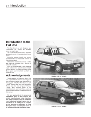 4
4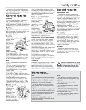 5
5 6
6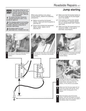 7
7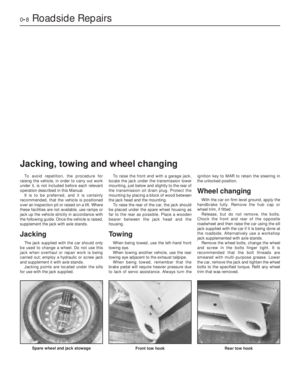 8
8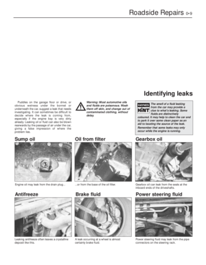 9
9 10
10 11
11 12
12 13
13 14
14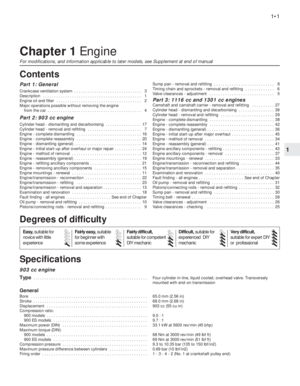 15
15 16
16 17
17 18
18 19
19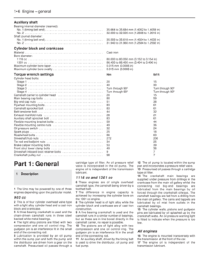 20
20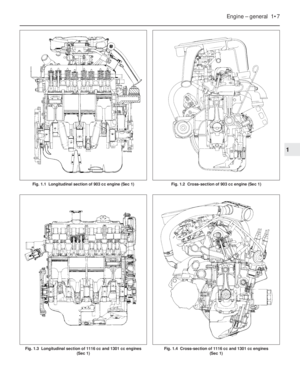 21
21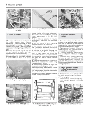 22
22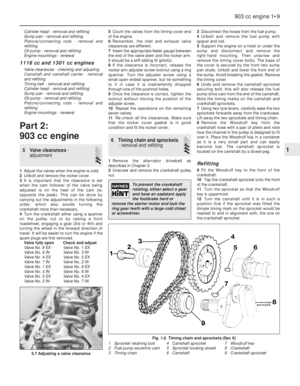 23
23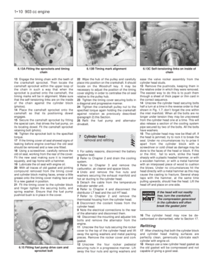 24
24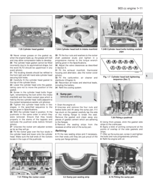 25
25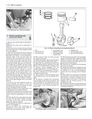 26
26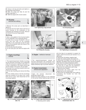 27
27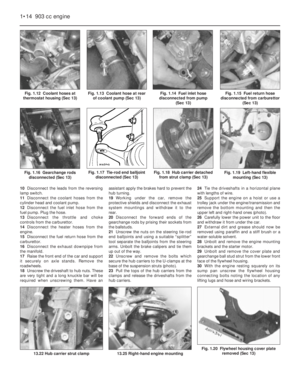 28
28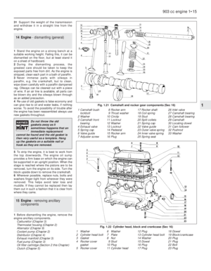 29
29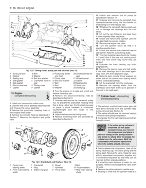 30
30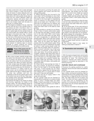 31
31 32
32 33
33 34
34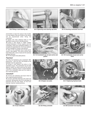 35
35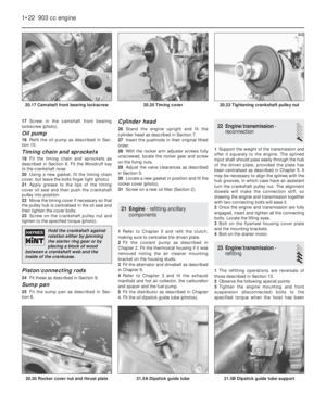 36
36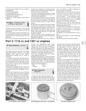 37
37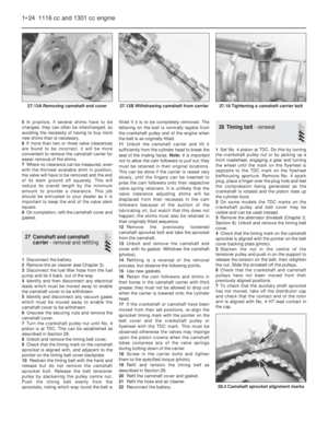 38
38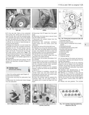 39
39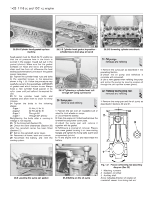 40
40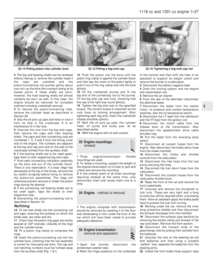 41
41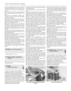 42
42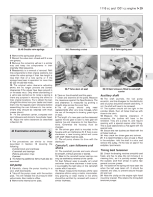 43
43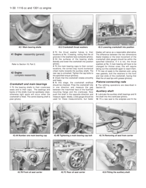 44
44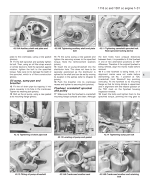 45
45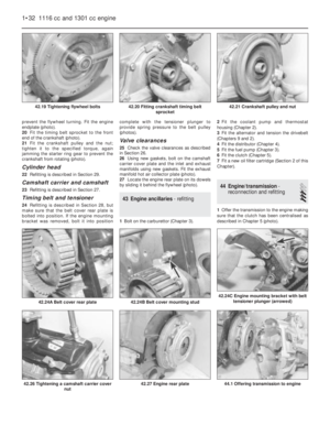 46
46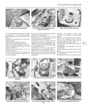 47
47 48
48 49
49 50
50 51
51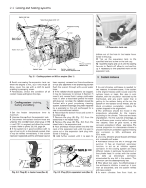 52
52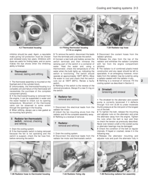 53
53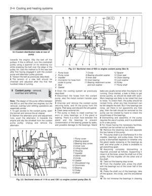 54
54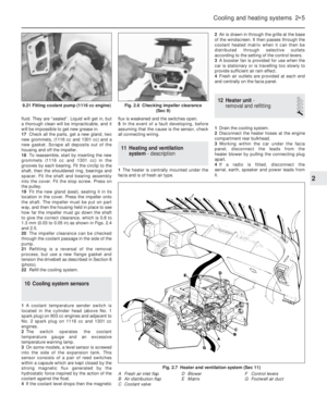 55
55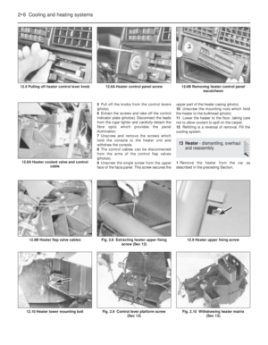 56
56 57
57 58
58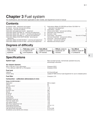 59
59 60
60 61
61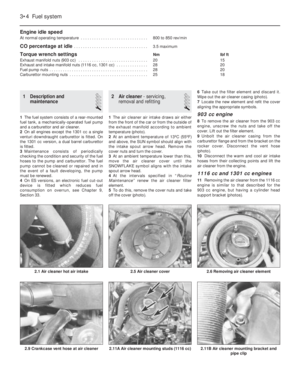 62
62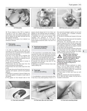 63
63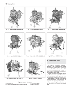 64
64 65
65 66
66 67
67 68
68 69
69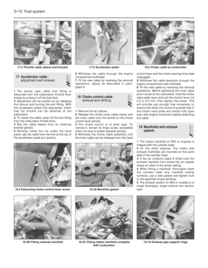 70
70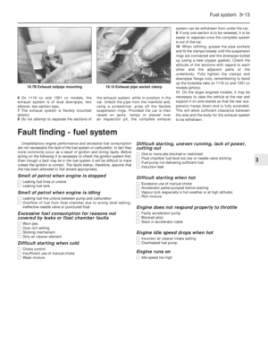 71
71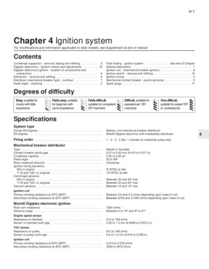 72
72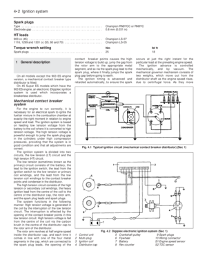 73
73 74
74 75
75 76
76 77
77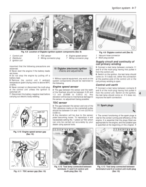 78
78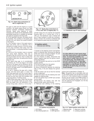 79
79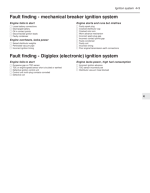 80
80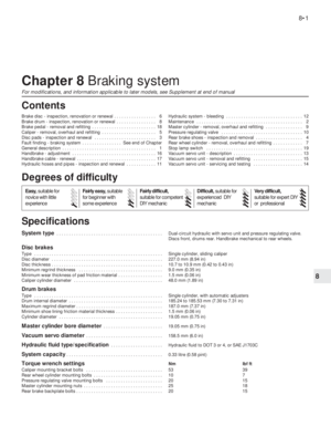 81
81 82
82 83
83 84
84 85
85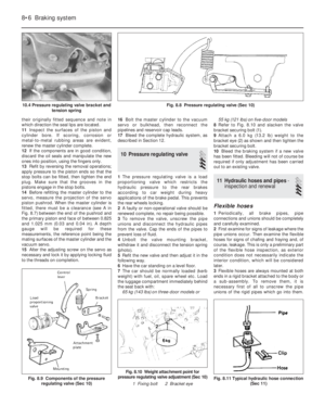 86
86 87
87 88
88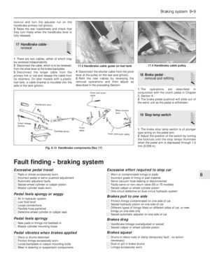 89
89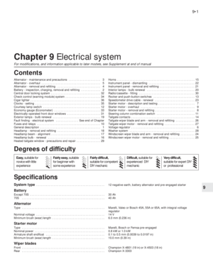 90
90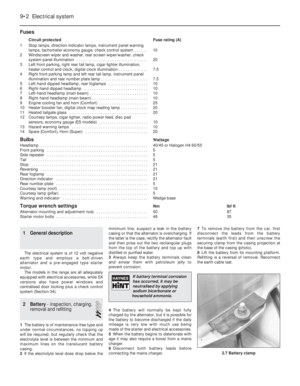 91
91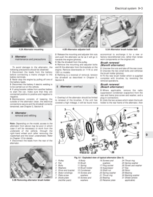 92
92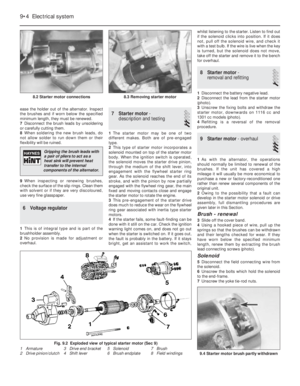 93
93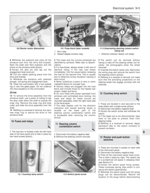 94
94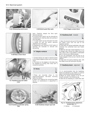 95
95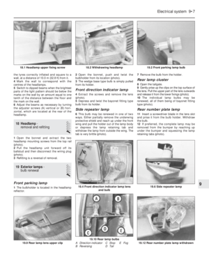 96
96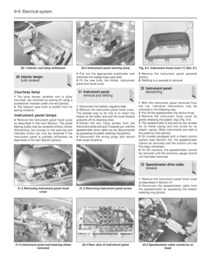 97
97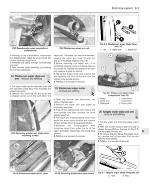 98
98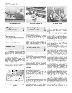 99
99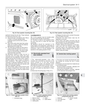 100
100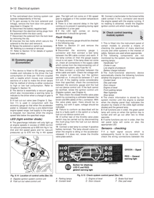 101
101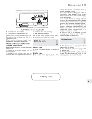 102
102 103
103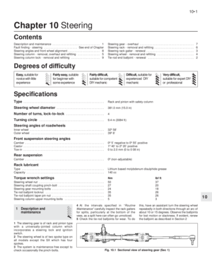 104
104 105
105 106
106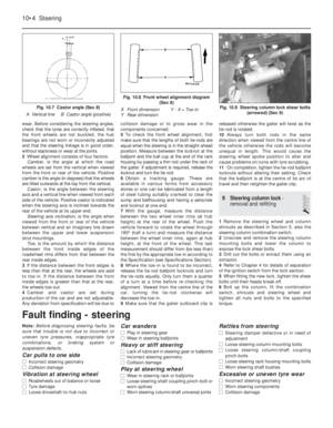 107
107 108
108 109
109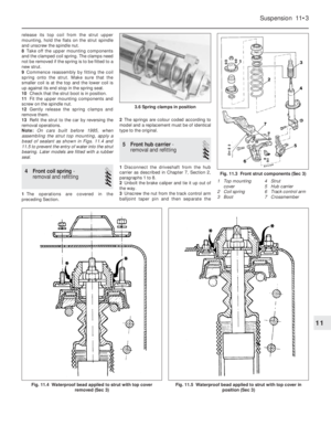 110
110 111
111 112
112 113
113 114
114 115
115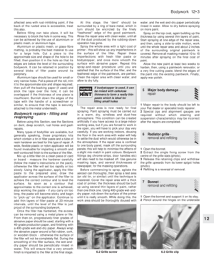 116
116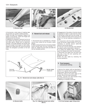 117
117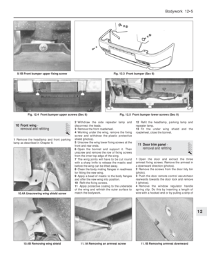 118
118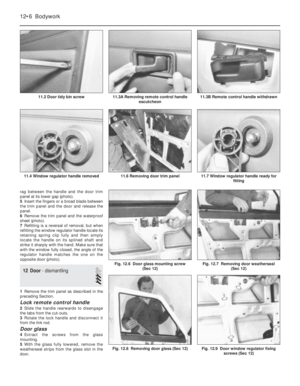 119
119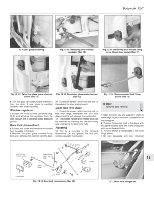 120
120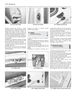 121
121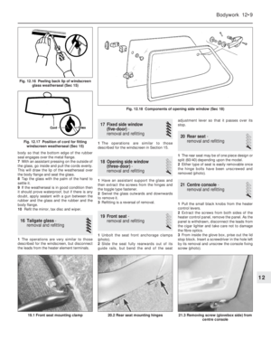 122
122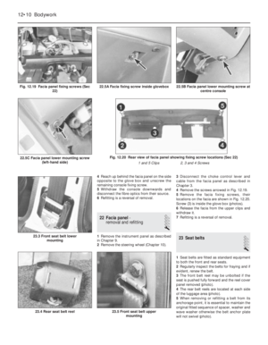 123
123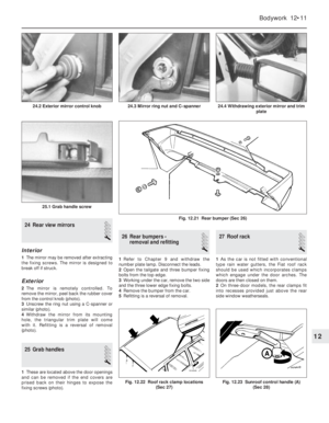 124
124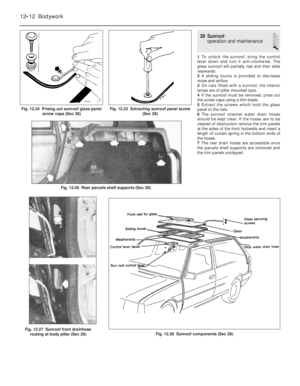 125
125 126
126 127
127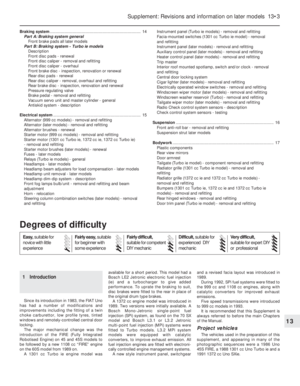 128
128 129
129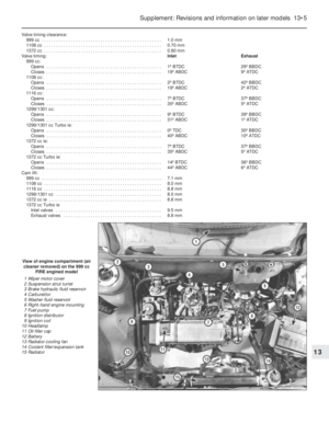 130
130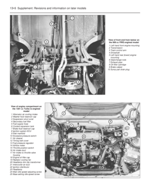 131
131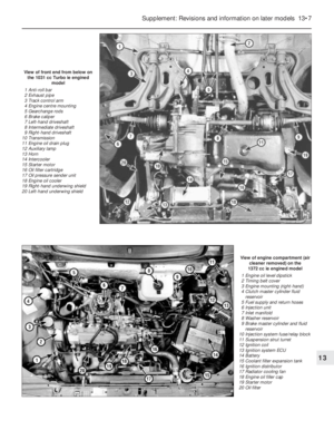 132
132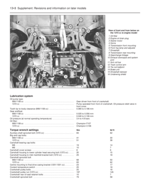 133
133 134
134 135
135 136
136 137
137 138
138 139
139 140
140 141
141 142
142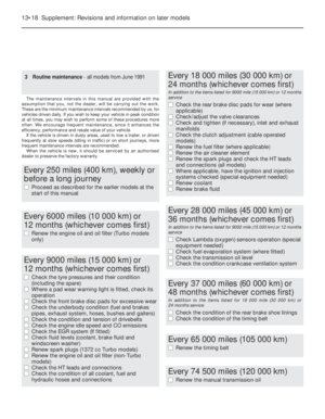 143
143 144
144 145
145 146
146 147
147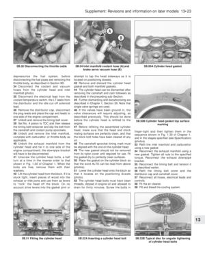 148
148 149
149 150
150 151
151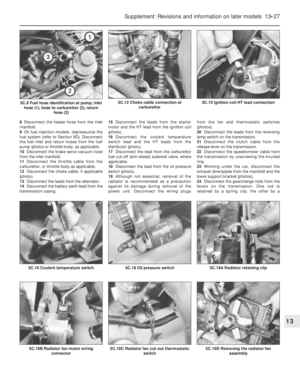 152
152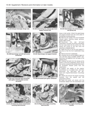 153
153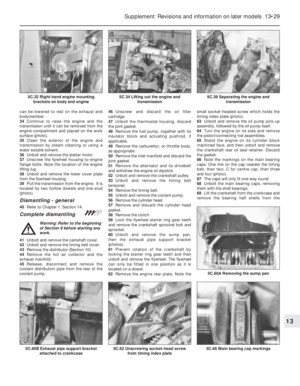 154
154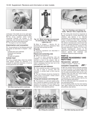 155
155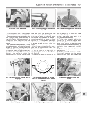 156
156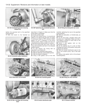 157
157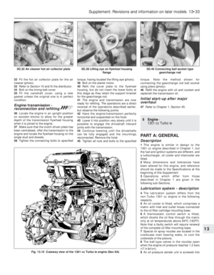 158
158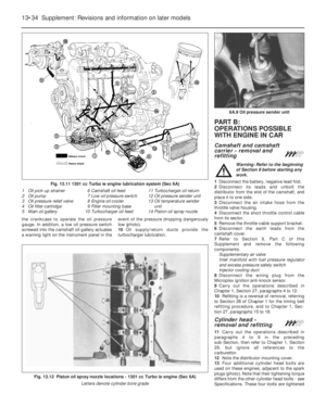 159
159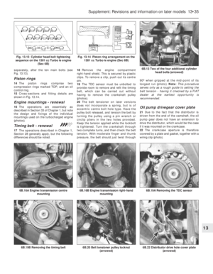 160
160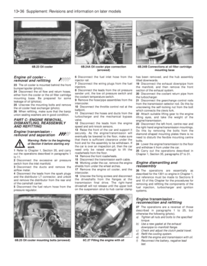 161
161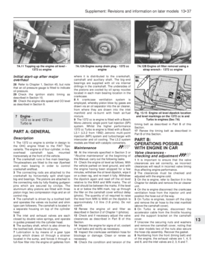 162
162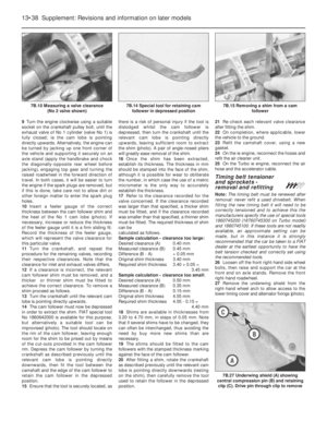 163
163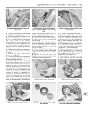 164
164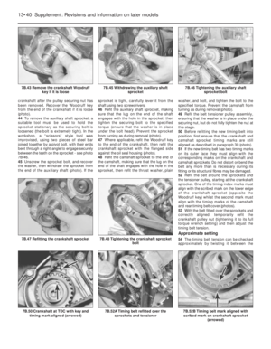 165
165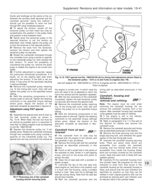 166
166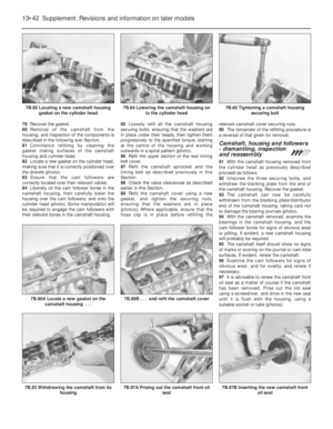 167
167 168
168 169
169 170
170 171
171 172
172 173
173 174
174 175
175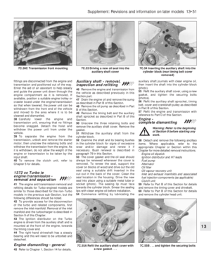 176
176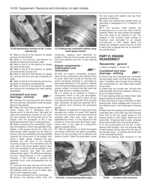 177
177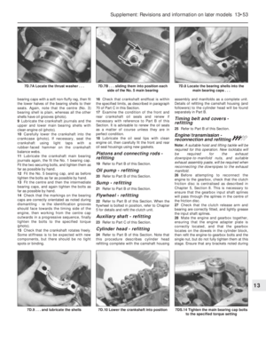 178
178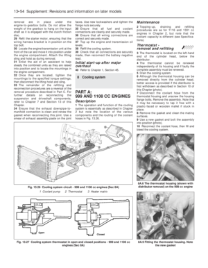 179
179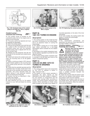 180
180 181
181 182
182 183
183 184
184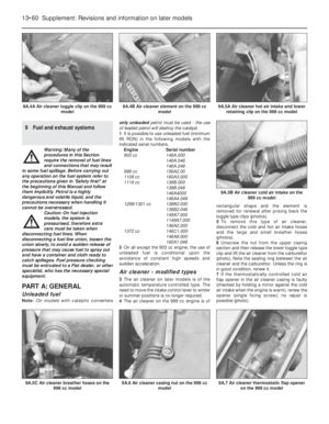 185
185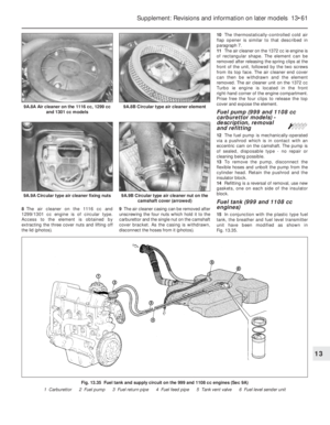 186
186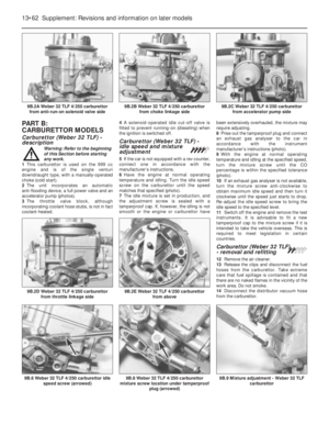 187
187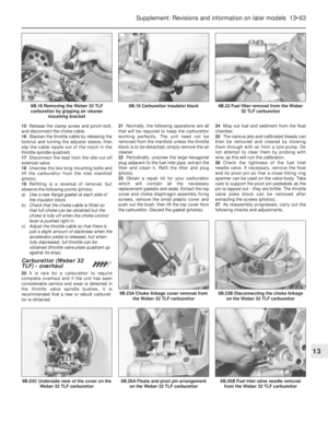 188
188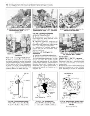 189
189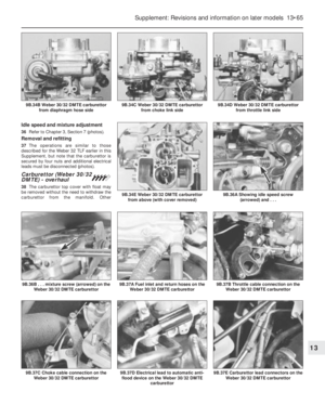 190
190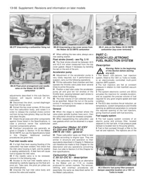 191
191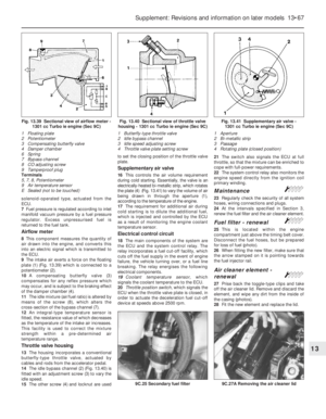 192
192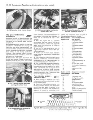 193
193 194
194 195
195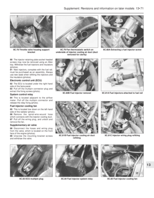 196
196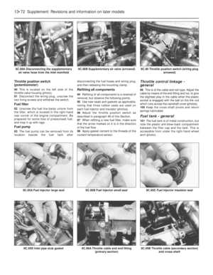 197
197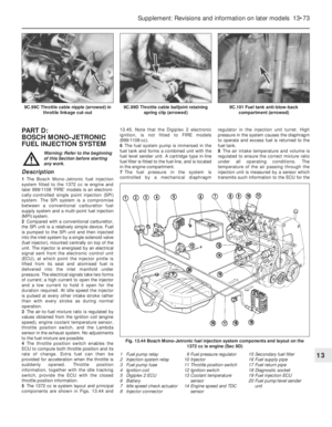 198
198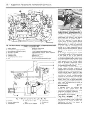 199
199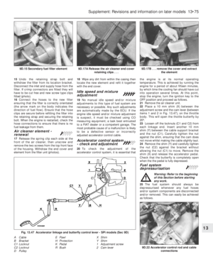 200
200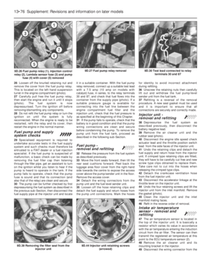 201
201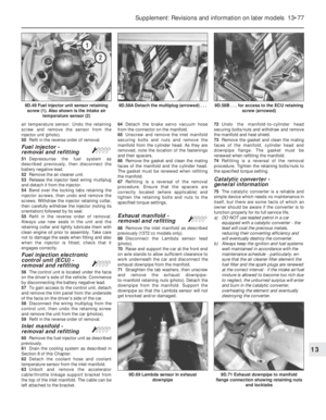 202
202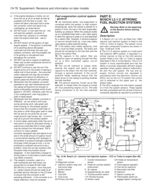 203
203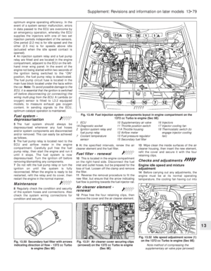 204
204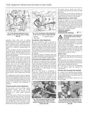 205
205 206
206 207
207 208
208 209
209 210
210 211
211 212
212 213
213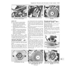 214
214 215
215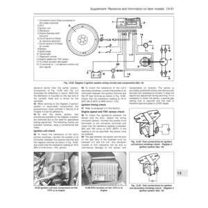 216
216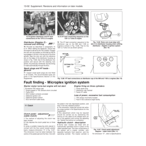 217
217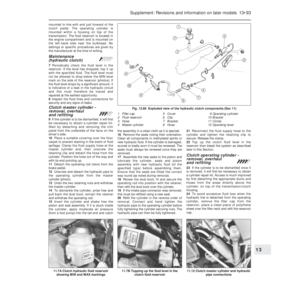 218
218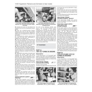 219
219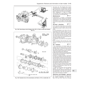 220
220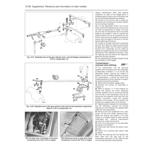 221
221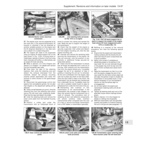 222
222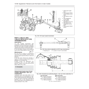 223
223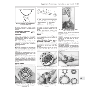 224
224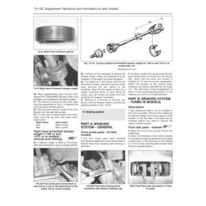 225
225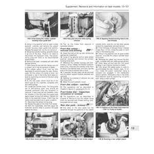 226
226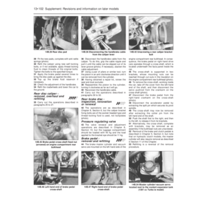 227
227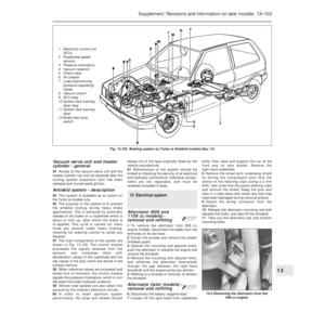 228
228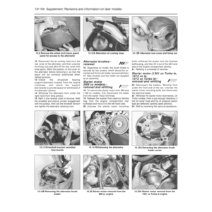 229
229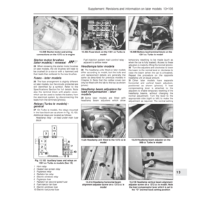 230
230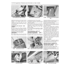 231
231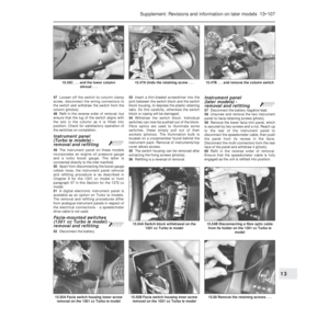 232
232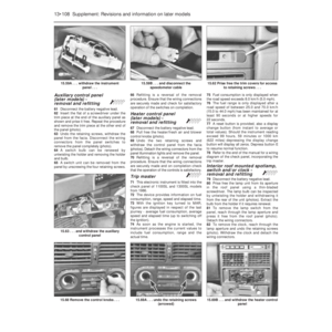 233
233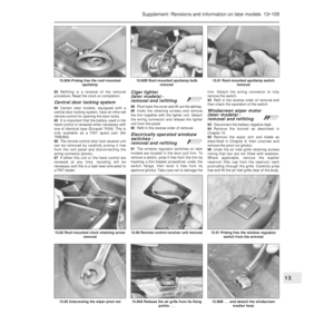 234
234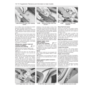 235
235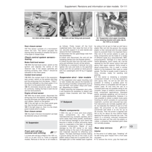 236
236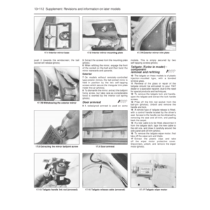 237
237 238
238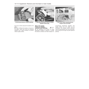 239
239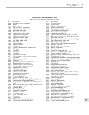 240
240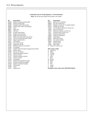 241
241 242
242 243
243 244
244 245
245 246
246 247
247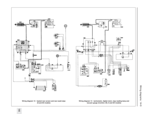 248
248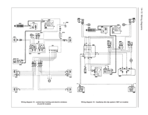 249
249 250
250 251
251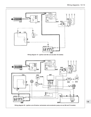 252
252 253
253 254
254 255
255 256
256 257
257 258
258 259
259 260
260 261
261 262
262 263
263 264
264 265
265 266
266 267
267 268
268 269
269 270
270 271
271 272
272 273
273 274
274 275
275 276
276 277
277 278
278 279
279 280
280 281
281 282
282 283
283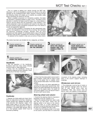 284
284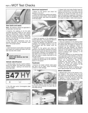 285
285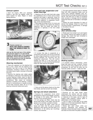 286
286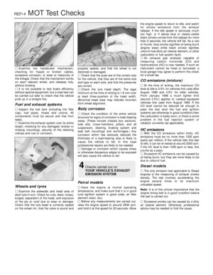 287
287 288
288 289
289 290
290 291
291 292
292 293
293 294
294 295
295 296
296 297
297 298
298 299
299 300
300 301
301 302
302