Page 193 of 303

Idle speed and mixture
adjustment¢
29Before carrying out any adjustments, the
engine must be at operating temperature, the
fan having cut in at second speed and then
switched off.
30Release the locknut and turn the main idle
speed screw in the throttle valve housing until
the engine idles at the specified speed. This
should be all that is necessary to obtain the
correct idle speed, as the throttle valve plate
base setting is set during production.
However, if wear has taken place, or incorrect
adjustment has been carried out previously,
proceed in the following way.
31Disconnect the intake duct from the
throttle valve housing. Release the locknut on
the base (small) adjusting screw, and turn thescrew until there is a clearance between the
lower edge of the throttle valve plate and the
throat wall of between 0.05 and 0.1 mm
(photos).
32With the engine still at operating
temperature, start the engine, and having
released the locknut, turn the main (large) idle
speed screw fully clockwise to close the
bypass passage.
33Now turn the base (small) screw until the
engine idles at between 700 and 800 rpm.
Tighten the locknut.
34Finally, turn the main (large) adjusting
screw to give an idle speed of between 800
and 900 rpm.
35It is unlikely that the mixture will require
alteration, but if it does, connect an exhaust
gas analyser to the car in accordance with the
equipment manufacturer’s instructions.
36With the engine at operating temperature,
prise out the tamperproof cap, and turn the
mixture screw, which is located in the airflow
meter, until the CO level is as given in the
Specifications. Turning the screw clockwise
richens the mixture, turning it anti-clockwise
weakens the mixture. Use a close-fitting Allen
key for the adjustment (photo).
Fuel injection system -
electrical testsª
37When carrying out checks to trace a fault
in the system, an ohmmeter should be used
for the following tests.
38Disconnect the multipin connector from
the ECU, and also the one from the system
control relay, and apply the probes of the
ohmmeter in accordance with the following
sequence to check for continuity in thecables. The component wiring plug will of
course be disconnected for the test.
ECU connector Component connector
plug terminal plug terminal
1 1 of ignition coil
2 2 of throttle position
switch
3 3 of throttle position
switch
4 50 of ignition switch
5 Earth
5 5 of airflow meter
7 7 of airflow meter
8 8 of airflow meter
9 9 of airflow meter
9 9 of throttle position
switch
9 18 of supplementary air
valve
9 87 main relay socket
10 10 of coolant temperature
sensor
12 Injector terminals
13 Earth
System control Component connector
relay connector plug terminal
plug terminal
1 1 of ignition coil
15 15 of ignition switch
30 Battery positive
31 Earth
50 50 of ignition switch
87 Injector terminals
87 18 of throttle position
switch
87 9 of ECU multipin socket
87b Fuel pump (fused)
13•68 Supplement: Revisions and information on later models
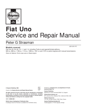
Fig. 13.42 ECU and component connector plug terminals - 1301 cc Turbo ie engine (Sec 9C)
For colour code see main wiring diagrams
9C.31C Checking throttle valve plate
opening with a feeler blade
9C.36 Using an Allen key to adjust the
mixture (CO level)
9C.31B Idle speed base setting screw (1)
and main adjustment screw (2)9C.31A Disconnecting the throttle valve
housing intake duct9C.27B Removing the air cleaner element
Page 194 of 303
.
Airflow meter")
39Now use the ohmmeter to check the
resistance of the following components.
Supplementary air valve
40Resistance between the terminals should
be between 40 and 60 ohms at 20ºC (68ºF).
Airflow meter
41Resistance between terminals 5 and 8 of
the potentiometer should be between 330 and
360 ohms at 20ºC (68ºF).
42Resistance between terminals 8 and 9 of
the internal circuit should be between 190 and
210 ohms at 20ºC (68ºF) and between 170
and 190 ohms at 60ºC (140ºF).
Coolant temperature sensor
43At 20ºC (68ºF) the resistance should be
between 2 and 4 k ohms. At 50ºC (122ºF) the
resistance should be between 600 and
900 ohms. At 90ºC (194ºF) the resistance
should be between 100 and 300 ohms.
Fuel injectors
44The winding resistance should be
between 15 and 17 ohms at 20ºC (68ºF).
Throttle position switch
45With the throttle butterfly valve closed,
there should be continuity between ter-
minals 18 and 2, and with the valve fully open,
there should be no continuity between
terminals 18 and 3.
46The throttle position switch should not be
disturbed unless absolutely necessary. If it
has to be removed, then refit it so that themicroswitch is heard to click immediately the
throttle butterfly is opened.
Fuel injection system -
mechanical tests ª
Fuel pump
47To test the pressure of the fuel pump, a
pressure gauge will be required, connected
into the fuel delivery hose.
48Remove the multipin plug from the system
control relay and bridge terminals 87b and 30.
49Turn the ignition switch on. The pump
should operate and indicate a pressure of
between 2.8 and 3.0 bars (40 and 44 lbf/in
2).
50To check the operation of the peak
pressure regulator, pinch the fuel return hose.
If the fuel pressure increases, the regulator
must be faulty, and should be renewed.
51Check that the fuel pressure increases
when, with the engine idling, the accelerator is
depressed sharply.
Supplementary air valve
52With the engine at normal operating
temperature and idling, pinch the
supplementary air valve hose using a pair of
pliers. The engine speed should not drop by
more than 50 rpm. If it does, renew the valve.
Fuel injection system
components -
removal and refitting
ª
53Disconnect the battery before carrying out
any of the following operations.
Air cleaner
54Remove the cover and filter element as
previously described.
55Disconnect the duct from the air cleaner
casing, and then unbolt and remove the
casing. Note that the lower bracket bolt need
not be completely removed, only unscrewed,
due to the design of the bracket. The air
cleaner metal duct is routed over the top of
the radiator (photos).
Airflow meter
56Release the securing clip and disconnect
the air intake duct (photo).
57Release the securing clip and disconnect
the air outlet duct (photo).
58Disconnect the wiring plug.
59Unscrew the fixing screws and remove
the airflow meter from its mounting bracket.
Supplement: Revisions and information on later models 13•69
9C.55B Removing the air cleaner casing
upper bracket9C.55A Disconnecting the duct from the air
cleanerFig. 13.43 System control relay connector
plug terminals 1301 cc Turbo ie engine
(Sec 9C)
9C.57 Air outlet duct securing clip removal
from airflow meter
9C.55C Air cleaner casing lower bracket
and bolt (arrowed)
9C.56 Air intake duct at airflow meter
(securing clip arrowed)9C.55D Air cleaner metal duct over
radiator
13
Page 195 of 303
.
61Anticipate some loss of pressurised fuel,
and then disconnect the fuel hose from the
regulator. Unbolt and remove the")
Fuel pressure regulator
60Disconnect the vacuum hose from the
regulator (photo).
61Anticipate some loss of pressurised fuel,
and then disconnect the fuel hose from the
regulator. Unbolt and remove the unit.
Excessive air pressure switch
62This is screwed into the end of the inlet
manifold. Disconnect the electrical leads and
unscrew the switch.
Coolant temperature sensor
63This is screwed into the cylinder head and
has wires connected to it. Drain the cooling
system before commencing operations.
64Disconnect the wiring plug and unscrew
the sensor.
Throttle valve housing and inlet
manifold
65Disconnect the air inlet hose from the
throttle valve housing, and also the
supplementary air valve hose.
66Disconnect the throttle control cable by
swivelling the grooved sector and slipping the
cable nipple from its recess.
67Disconnect the wiring plug from the
throttle position (potentiometer) switch.
68Unbolt the fuel pressure regulator/wiring
loom bracket, and also the wiring loom
bracket at the other end of the inlet manifold.
Move the wiring loom aside.
69Unbolt and remove the throttle housing
support bracket.
70Disconnect the vacuum servo hose and
the fuel pressure regulator vacuum hosesfrom the inlet manifold (photos).
71Disconnect the leads from the excessive
air pressure switch.
72Unscrew the inlet manifold fixing nuts.
Note that double nuts are used at the ends of
the manifold in order to secure the exhaust
heat shield (photo). The shield should be
released and lowered to rest on the exhaust
manifold.
73Unscrew and remove the remaining two
nuts now exposed by lowering the heat shield
and lifting the inlet manifold away (photo).
74If necessary, the injectors and cooling
tube can be withdrawn, and the two twin inlet
pipe stubs removed. These are retained with
the exhaust manifolds using nuts and washers
(photo).
Fuel rail and injectors
75Disconnect the fuel delivery hose from the
fuel rail by unscrewing the union nut (photo).
Be prepared for some loss of pressurised fuel.
76Disconnect the fuel return hose.
77Unbolt the fuel pressure regulator and the
wiring loom brackets (photo).
78Disconnect the air intake hose from the
throttle valve housing, and then unbolt and
remove the throttle valve housing support
bracket (photo).
79Disconnect the hose from the injector
cooling fan, and also disconnect the fan
thermo-switch on the underside of the injector
cooling air duct (photo). Disconnect the
injector wiring plugs, and then slide out the
injector cooling air duct.
13•70 Supplement: Revisions and information on later models
9C.77 Wiring loom clip and bracket9C.75 Disconnecting the fuel delivery hose
union9C.74 Removing an inlet manifold twin
pipe stub
9C.73 Removing the inlet manifold9C.72 Double nuts at the end of the inlet
manifold
9C.70B Fuel pressure regulator vacuum
hose connection at the inlet manifold9C.70A Brake servo vacuum hose
connection to inlet manifold9C.60 Fuel pressure regulator
Page 196 of 303
.
81New injectors, complete with the fuel rail,
must be pu")
80The injector retaining plate socket-headed
screws may now be removed using an Allen
key. Withdraw the fuel injectors and insulators
(photos).
81New injectors, complete with the fuel rail,
must be purchased as an assembly. Always
use new seals when refitting the injectors and
the insulators (photos).
Electronic control unit (ECU)
82The ECU is located under the right-hand
side of the facia panel.
83Pull off the multipin connector plug and
extract the fixing screws (photo).
System control relay
84This is located adjacent to the airflow
meter. Pull off the multipin connector and
release the relay fixing (photo).
Fuel injector cooling fan
85This is located low down on the left-hand
side of the radiator (photo).
86Remove the spiral-wire-wound hose
which connects with the injector cooling duct.
87Pull off the wiring plug, and unbolt and
remove the fan.
Supplementary air valve
88Disconnect the hoses and wiring plug
from the valve, which is located on the front
face of the engine (photos).
89Unscrew the mounting bracket screws
and withdraw the valve.
Supplement: Revisions and information on later models 13•71
9C.80A Extracting a fuel injector screw9C.79 Fan thermostatic switch on
underside of injector cooling air duct (duct
removed for clarity)
9C.85 Fuel injector cooling fan9C.84 Fuel injector system relay9C.83 ECU multipin plug
9C.81C Injector wiring plug refitting9C.81B Fuel injector cooling air duct
refitting
9C.81A Fuel injectors attached to fuel rail9C.80B Fuel injector removal
13
9C.78 Throttle valve housing support
bracket
Page 197 of 303

90This is located on the left side of the
throttle valve housing (photo).
91Disconnect the wiring plug, unscrew the
two fixing screws and withdraw the switch")
Throttle position switch
(potentiometer)
90This is located on the left side of the
throttle valve housing (photo).
91Disconnect the wiring plug, unscrew the
two fixing screws and withdraw the switch.
Fuel filter
92Unscrew the fuel line banjo unions from
the filter, which is located in the right-hand
rear corner of the engine compartment. Be
prepared for some loss of pressurised fuel,
and mop it up with rags.
Fuel pump
93The fuel pump can be removed from its
location beside the fuel tank afterdisconnecting the fuel hoses and wiring plug,
and then releasing the mounting clamp.
Refitting all components
94Refitting of all components is a reversal of
removal, but observe the following points.
95Use new seals and gaskets as applicable,
noting that three rubber seals are used on
each fuel injector and insulator (photos).
96Adjust the throttle position switch as
described in paragraph 46 of this Section.
97When refitting a new fuel filter, make sure
that the arrow marked on it is in the direction
of the fuel flow.
98Apply gasket cement to the threads of the
coolant temperature sensor.
Throttle control linkage -
general
99This is of the cable and rod type. Adjust the
cable by means of the end fitting and nut, to give
the slightest play in the cable when the plastic
socket is engaged with the ball on the link rod
which runs across the camshaft cover (photos).
100Keep the cross-shaft pivots and return
springs lubricated.
Fuel tank - general
101The fuel tank is of metal construction, but
note the plastic anti-blow-back compartment
between the filler cap and the tank. This is
accessible from under the right-hand wheel
arch (photo).
13•72 Supplement: Revisions and information on later models
9C.99B Throttle cable (secondary section)
and cross-shaft9C.99A Throttle cable and end fitting
(primary section)9C.95D Inlet pipe stub gasket
9C.95C Fuel injector insulator seal9C.95B Fuel injector small seal9C.95A Fuel injector large seal
9C.90 Throttle position switch (wiring plug
arrowed)9C.88B Supplementary air valve (arrowed)9C.88A Disconnecting the supplementary
air valve hose from the inlet manifold
Page 198 of 303

PART D:
BOSCH MONO-JETRONIC
FUEL INJECTION SYSTEM
Warning: Refer to the beginning
of this Section before starting
any work.
Description
1The Bosch Mono-Jetronic fuel injection
system fitted to the 1372 cc ie engine and
later 999/1108 ‘FIRE’ models is an electroni-
cally-controlled single point injection (SPi)
system. The SPi system is a compromise
between a conventional carburettor fuel
supply system and a multi-point fuel injection
(MPi) system.
2Compared with a conventional carburettor,
the SPi unit is a relatively simple device. Fuel
is pumped to the SPi unit and then injected
into the inlet system by a single solenoid valve
(fuel injector), mounted centrally on top of the
unit. The injector is energised by an electrical
signal sent from the electronic control unit
(ECU), at which point the injector pintle is
lifted from its seat and atomised fuel is
delivered into the inlet manifold under
pressure. The electrical signals take two forms
of current; a high current to open the injector
and a low current to hold it open for the
duration required. At idle speed the injector
is pulsed at every other intake stroke rather
than with every stroke as during normal
operation.
3The air-to-fuel mixture ratio is regulated by
values obtained from the ignition coil (engine
speed), engine coolant temperature sensor,
throttle position switch, and the Lambda
sensor in the exhaust system. No adjustments
to the fuel mixture are possible.
4The throttle position switch enables the
ECU to compute both throttle position and its
rate of change. Extra fuel can then be
provided for acceleration when the throttle is
suddenly opened. Throttle position
information, together with the idle tracking
switch, provide the ECU with the closed
throttle position information.
5The 1372 cc ie system layout and principal
components are shown in Figs. 13.44 and13.45. Note that the Digiplex 2 electronic
ignition, is not fitted to FIRE models
(999/1108 cc).
6The fuel system pump is immersed in the
fuel tank and forms a combined unit with the
fuel level sender unit. A cartridge type in-line
fuel filter is fitted to the fuel line, and is located
in the engine compartment.
7The fuel pressure in the system is
controlled by a mechanical diaphragmregulator in the injection unit turret. High
pressure in the system causes the diaphragm
to operate and excess fuel is returned to the
fuel tank.
8The air intake temperature and volume is
regulated to ensure the correct mixture ratio
under all operating conditions. The
temperature of the air passing through the
injection unit is measured by a sensor which
transmits such information to the ECU for the
Supplement: Revisions and information on later models 13•73
9C.101 Fuel tank anti-blow-back
compartment (arrowed)9C.99D Throttle cable balljoint retaining
spring clip (arrowed)9C.99C Throttle cable nipple (arrowed) in
throttle linkage cut-out
Fig. 13.44 Bosch Mono-Jetronic fuel injection system components and layout on the
1372 cc ie engine (Sec 9D)
1 Fuel pump relay
2 Injection system relay
3 Fuel pump fuse
4 Ignition coil
5 Digiplex 2 ECU
6 Battery
7 Idle speed check actuator
8 Injector connector9 Fuel pressure regulator
10 Injector
11 Throttle position switch
12 Ignition switch
13 Coolant temperature
sensor
14 Engine speed and TDC
sensor15 Secondary fuel filter
16 Fuel supply pipe
17 Fuel return pipe
18 Diagnostic socket
19 Fuel injection ECU
20 Fuel pump/level sender
unit13
Page 199 of 303
. A conventional
paper type air filter element is used and this
must be renewed at the specified intervals.
9The ECU is specific to the model type, its
function being to co")
necessary processing (photo). A conventional
paper type air filter element is used and this
must be renewed at the specified intervals.
9The ECU is specific to the model type, its
function being to control the fuel system
under all operating conditions, including
starting from cold - it richens the fuel mixture
as required but at the same time prevents
flooding. As the engine temperature rises, the
injection impulses are progressively reduced
until the normal operation temperature is
reached.
10An integral emergency system enables
the fuel injection system to remain operational
in the event of any of the following
components malfunctioning. These items are
the coolant temperature sensor, the air intake
sensor, the Lambda sensor, the idle speed
check actuator and the throttle position
switch. In the event of the throttle position
switch malfunctioning, the fuel system
becomes automatically inoperative.
11The catalytic converter fitted in the
exhaust system minimises the amount of
pollutants which escape into the atmosphere.
The Lambda sensor in the exhaust system
provides the fuel injection system ECU with
constant feedback which enables it to adjust
the mixture to provide the best possible
conditions for the converter to operate. The
fuel tank ventilation is contained within the
system. This is done by feeding any excess
vapours through a carbon filter back into the
engine intake, using solenoids and valves, as
shown in Fig. 13.46.
MaintenanceÁ
12Regularly check the condition and
security of the system hoses and
connections. Also check the system wiring
connections for condition and security.
13At the specified intervals, renew the air
cleaner element and the fuel filter.
Fuel filter - renewalÁ
14The in-line fuel filter is secured to the
right-hand suspension turret in the engine
compartment. To remove the filter, first
depressurize the fuel in the system as
described later in this Part.
13•74 Supplement: Revisions and information on later models
Fig. 13.46 Fuel evaporation control system (Sec 9D)
1 Fuel tank
2 Two-way safety valve
3 Throttle body4 Two-way vapour vent
valve
5 Vapour cut-off solenoid6 Carbon filter
7 Elbi solenoid
8 ECU
9D.8 Atmospheric air intake for air
temperature sensor (1). Also shown are the
supply and return fuel line connections (2
and 3) and the throttle position sensor (4)
Fig. 13.45 Mono-Jetronic fuel injection component locations in the engine compartment
- 1372 cc ie engine (Sec 9D)
1 Injector resistor
2 Lambda sensor signal connector
3 Lambda sensor heating connector
4 Secondary fuel filter
5 Fuel return pipe
6 Fuel supply pipe
7 Coolant temperature sensor
8 ECU9 Injector holder turret
10 Lambda sensor
11 Nut for adjusting accelerator cable
12 Engine speed and TDC sensor connector
13 Ignition control unit
14 Ignition coil
15 Diagnostic socket
16 Fuel pump relay and system relay
Page 200 of 303

15Undo the retaining strap bolt and
withdraw the filter from its location bracket.
Disconnect the inlet and supply hose from the
filter. If crimp connectors are fitted they will
have to be cut free and new screw type clips
fitted (photo).
16Connect the hoses to the new filter
ensuring that the filter is correctly orientated
(the arrow mark on the body indicates the
direction of fuel flow). Ensure that the hose
clips are secure before refitting the filter into
the retaining strap and securing the retaining
bolt. When the engine is restarted, check the
hose connections to ensure that there is no
fuel leakage from them.
Air cleaner element -
renewalÁ
17Release the spring clip each side at the
front of the air cleaner, then unscrew and
remove the two screws from the top front face
of the housing. Withdraw the end cover and
element from the filter unit (photos).18Wipe any dirt from within the casing then
locate the new element and refit it together
with the end cover.
Idle speed and mixture
adjustment°
19No manual idle speed and/or mixture
adjustments to this type of fuel system are
necessary or possible. Any such adjustments
are automatically made by the ECU. If the
engine idle speed and/or mixture adjustment
is suspect, it must be checked using CO
measuring equipment; a task best entrusted
to a FIAT dealer or a competent garage. The
most probable cause of a malfunction is likely
to be a defective sensor or incorrectly
adjusted accelerator control cable.
Accelerator control system
- check and adjustment#
20To check the adjustment of the
accelerator control system, it is essential thatthe engine is at its normal operating
temperature. This is achieved by running the
engine for a period of about fifteen minutes,
by which time the cooling fan should have cut
into operation several times. At this point,
stop the engine, turn the ignition key to the
OFF position and proceed as follows.
21Remove the air cleaner unit.
22Place a 10 mm shim (X) between the
adjustment screw and the cam lever (between
items 1 and 2 in Fig. 13.47), on the throttle
body. This will open the thottle butterfly by
20º.
23Loosen off the locknuts (C1 and C2) from
each linkage end. Insert another 10 mm
shim (Y) between the cable support bracket
and the nut (C1). Carefully tighten the nut
against the shim, ensuring that the cam does
not move whilst making the cable slightly taut.
24Remove the shim (Y) and carefully tighten
the nut (C2) against the bracket without
allowing the nut (C1) to move. Remove the
shim (X) and release the accelerator pedal.
Check that the butterfly is completely open
when the the pedal is fully depressed.
Fuel system
depressurisationÁ
Warning: Refer to the beginning
of this Section before starting
any work.
25The fuel system should always be
depressurised whenever any fuel hoses
and/or system components are disconnected
and/or removed. This can easily be achieved
as follows.
Supplement: Revisions and information on later models 13•75
9D.17B . . . remove the cover and extract
the element9D.17A Release the air cleaner end cover
retaining clips . . .9D.15 Secondary fuel filter element
9D.22 Accelerator control rod and cable
connections
A Cable
B Bracket
C1 Locknut
C2 Locknut
D PulleyE Pawl
H Protection
K Pedal
R BushX Shim
Y Shim
1 Adjustment screw
2 Cam lever
13
Fig. 13.47 Accelerator linkage and butterfly control lever - SPi models (Sec 9D)
 1
1 2
2 3
3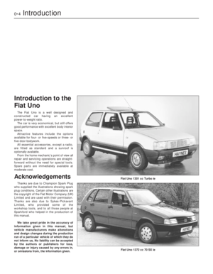 4
4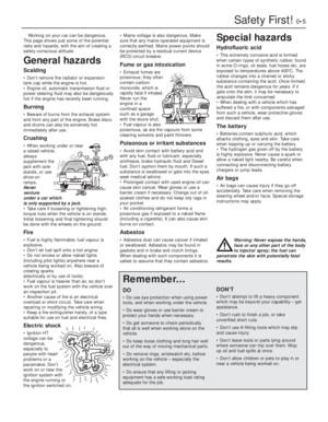 5
5 6
6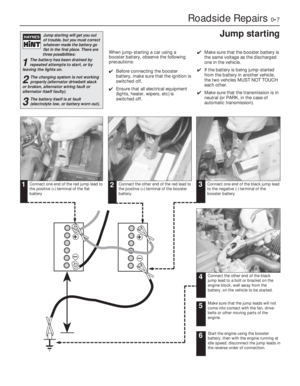 7
7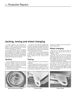 8
8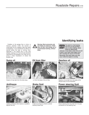 9
9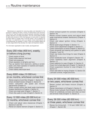 10
10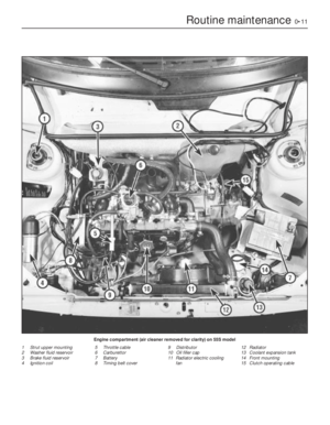 11
11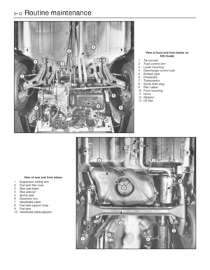 12
12 13
13 14
14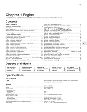 15
15 16
16 17
17 18
18 19
19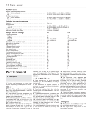 20
20 21
21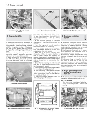 22
22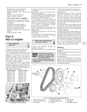 23
23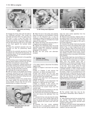 24
24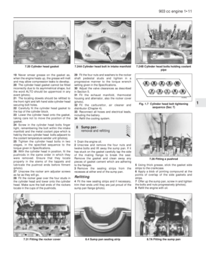 25
25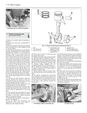 26
26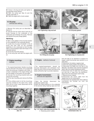 27
27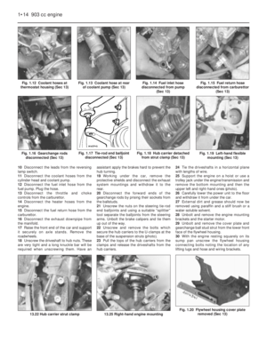 28
28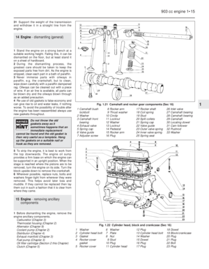 29
29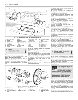 30
30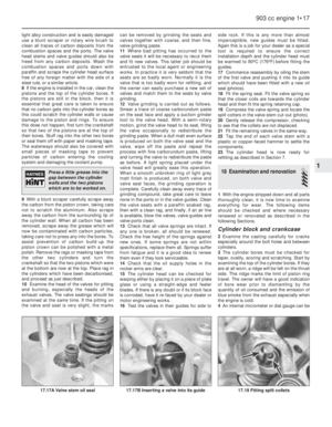 31
31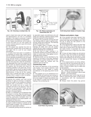 32
32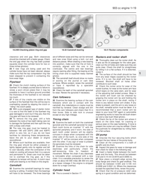 33
33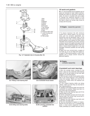 34
34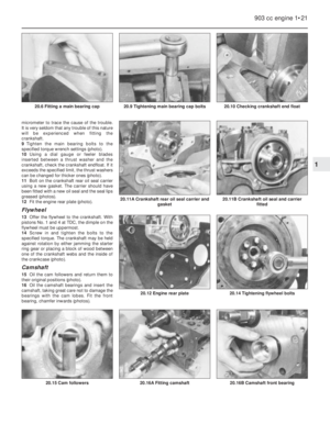 35
35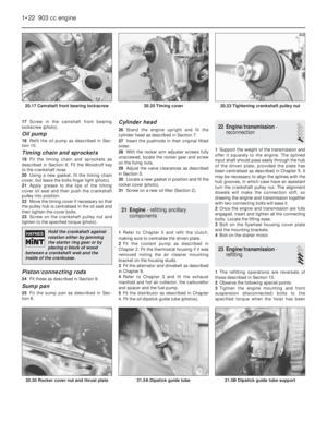 36
36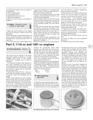 37
37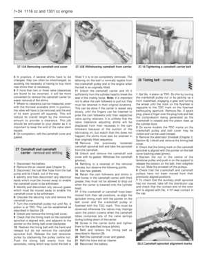 38
38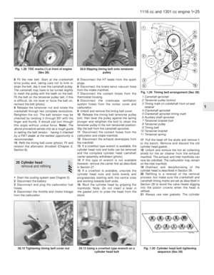 39
39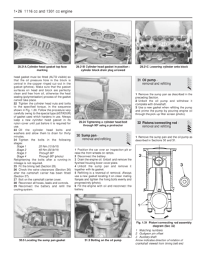 40
40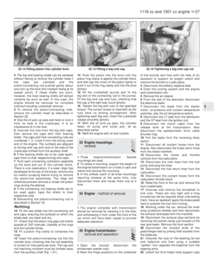 41
41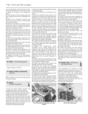 42
42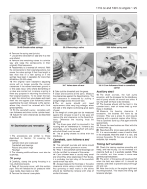 43
43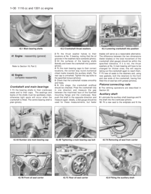 44
44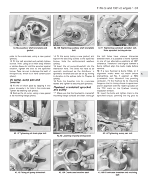 45
45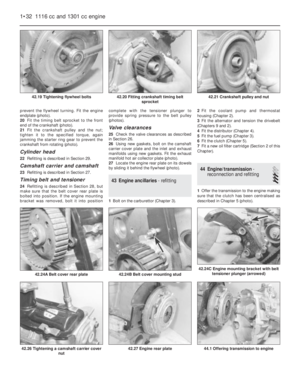 46
46 47
47 48
48 49
49 50
50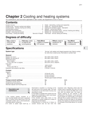 51
51 52
52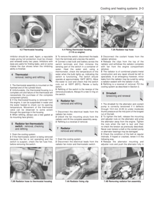 53
53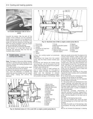 54
54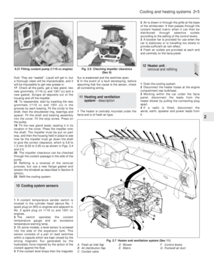 55
55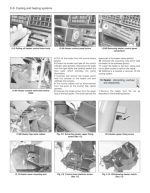 56
56 57
57 58
58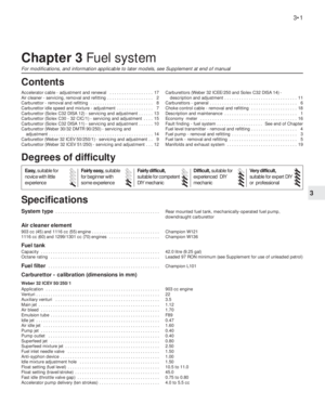 59
59 60
60 61
61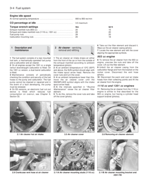 62
62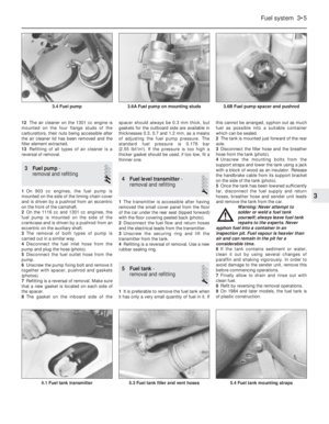 63
63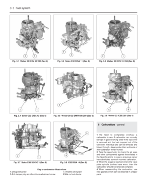 64
64 65
65 66
66 67
67 68
68 69
69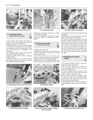 70
70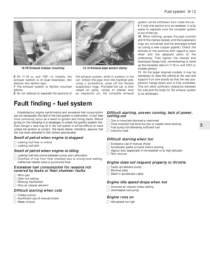 71
71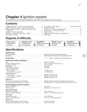 72
72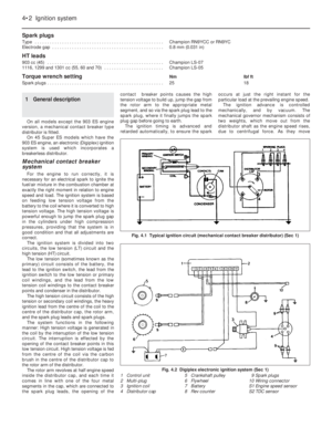 73
73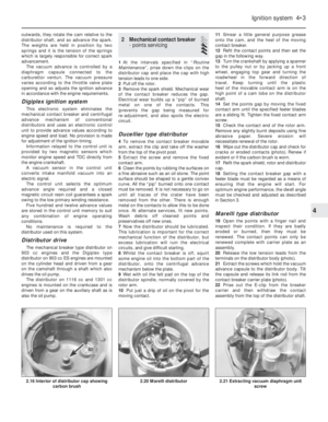 74
74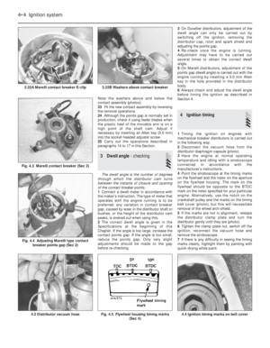 75
75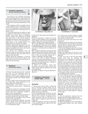 76
76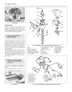 77
77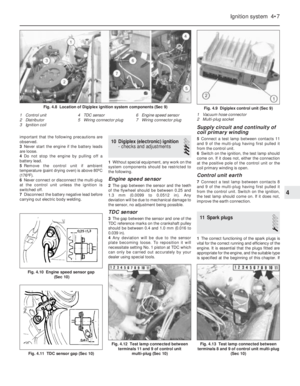 78
78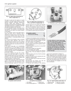 79
79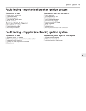 80
80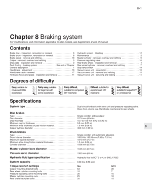 81
81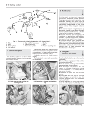 82
82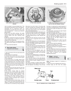 83
83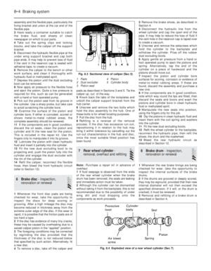 84
84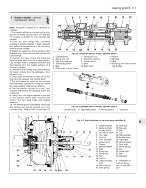 85
85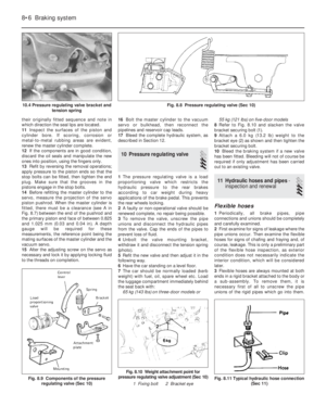 86
86 87
87 88
88 89
89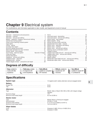 90
90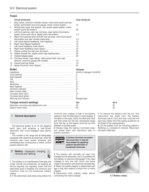 91
91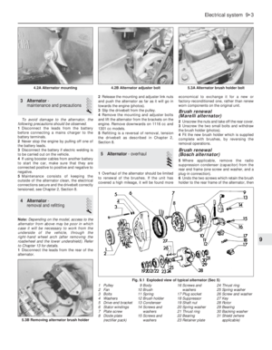 92
92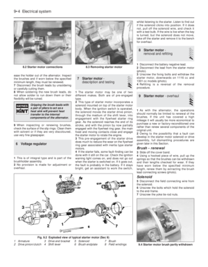 93
93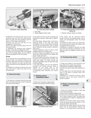 94
94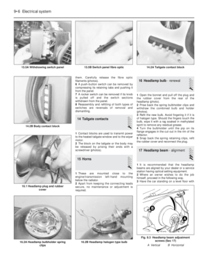 95
95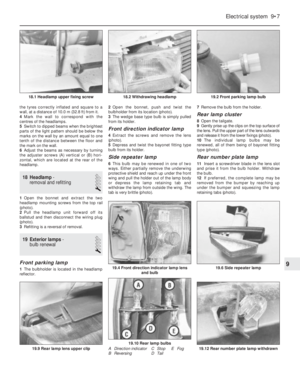 96
96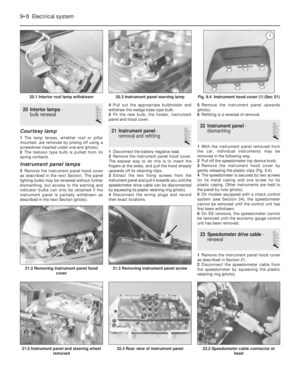 97
97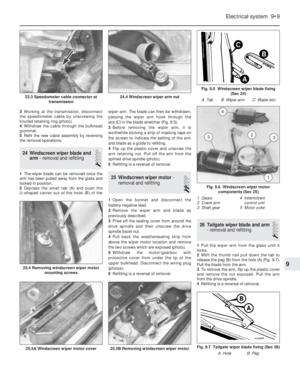 98
98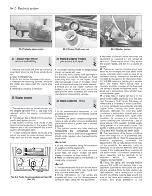 99
99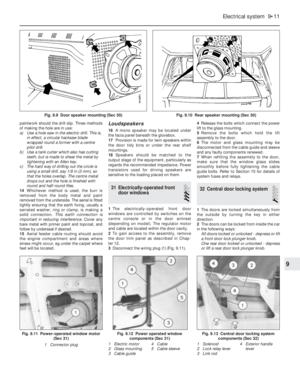 100
100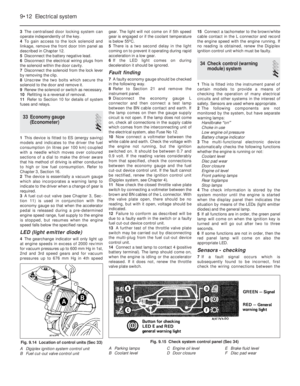 101
101 102
102 103
103 104
104 105
105 106
106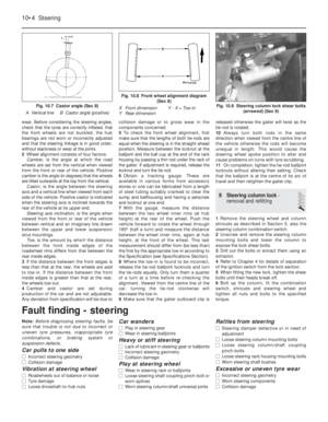 107
107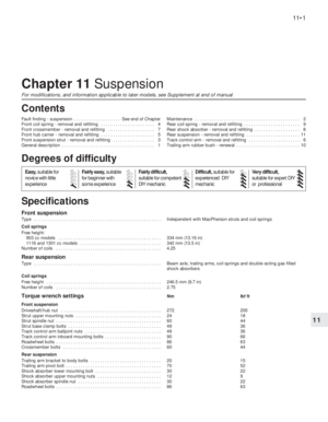 108
108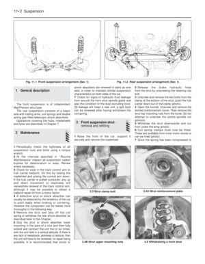 109
109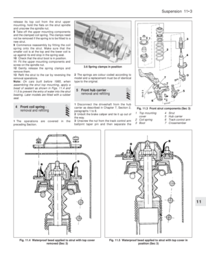 110
110 111
111 112
112 113
113 114
114 115
115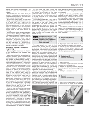 116
116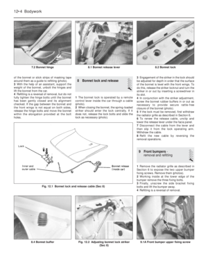 117
117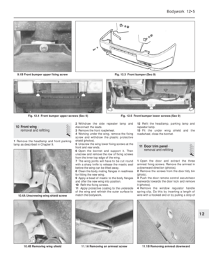 118
118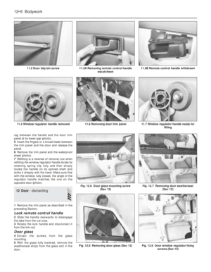 119
119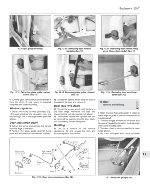 120
120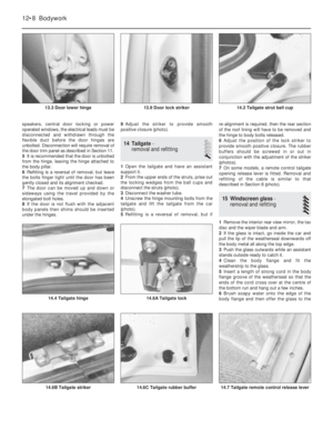 121
121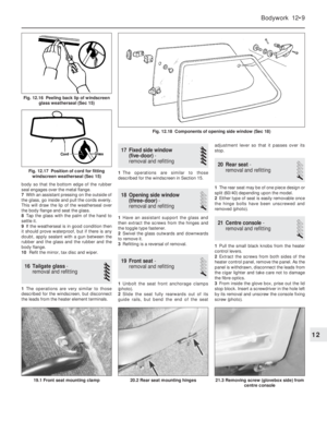 122
122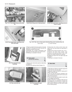 123
123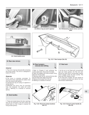 124
124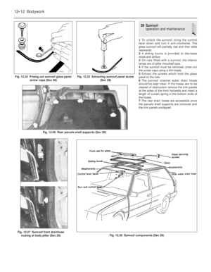 125
125 126
126 127
127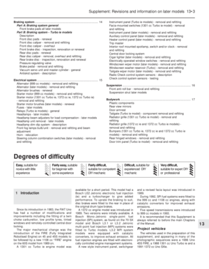 128
128 129
129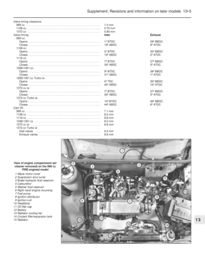 130
130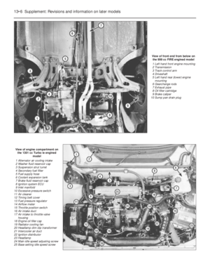 131
131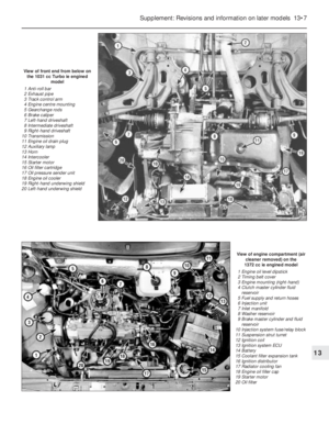 132
132 133
133 134
134 135
135 136
136 137
137 138
138 139
139 140
140 141
141 142
142 143
143 144
144 145
145 146
146 147
147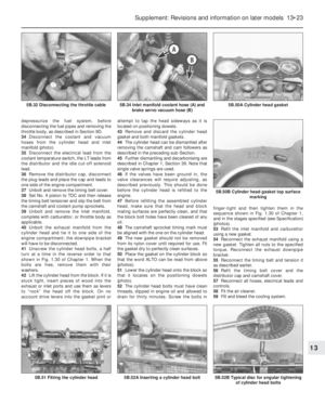 148
148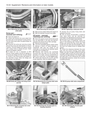 149
149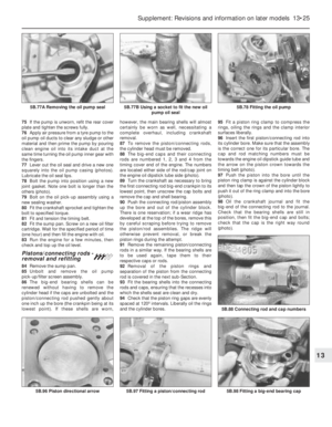 150
150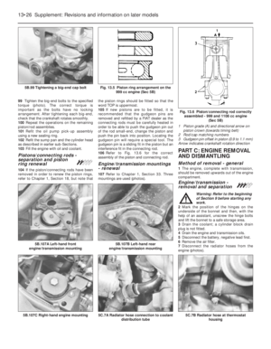 151
151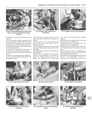 152
152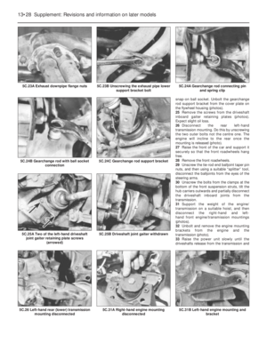 153
153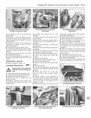 154
154 155
155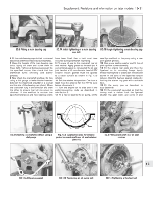 156
156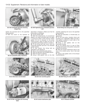 157
157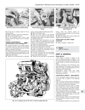 158
158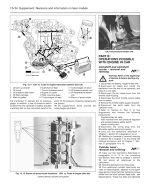 159
159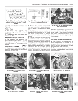 160
160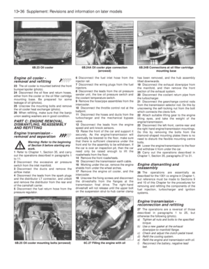 161
161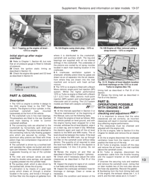 162
162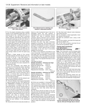 163
163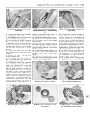 164
164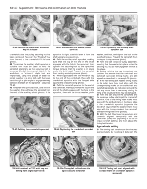 165
165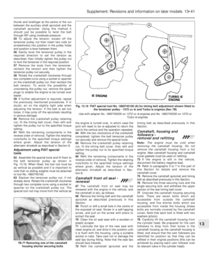 166
166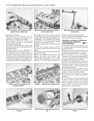 167
167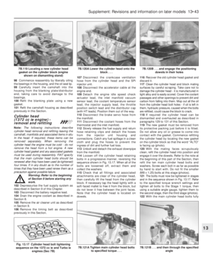 168
168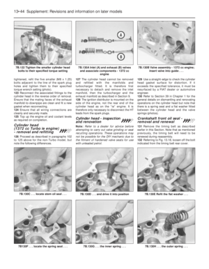 169
169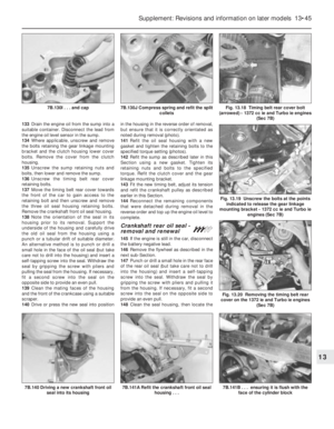 170
170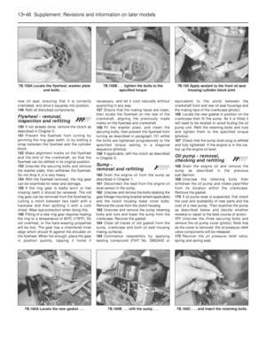 171
171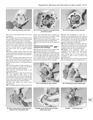 172
172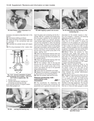 173
173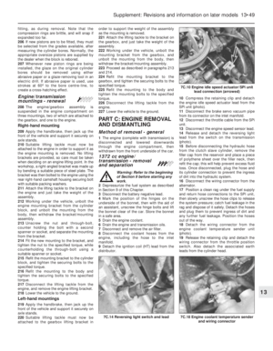 174
174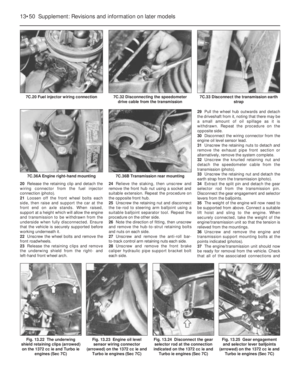 175
175 176
176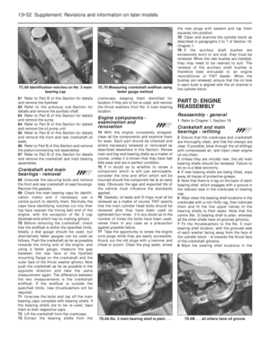 177
177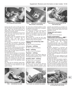 178
178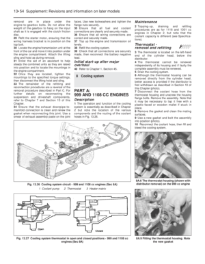 179
179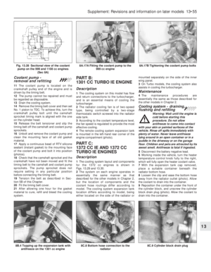 180
180 181
181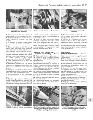 182
182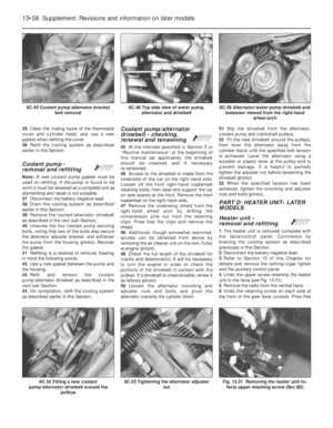 183
183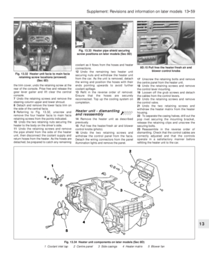 184
184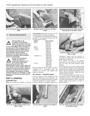 185
185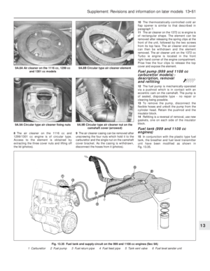 186
186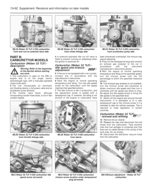 187
187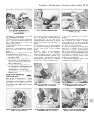 188
188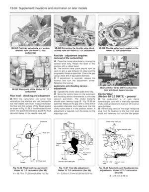 189
189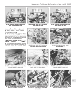 190
190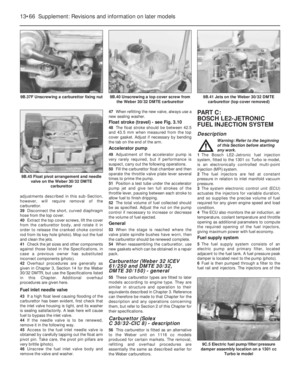 191
191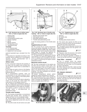 192
192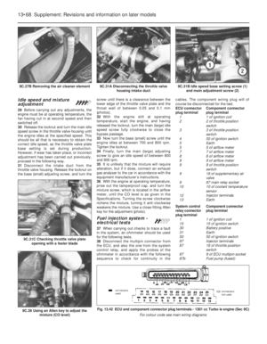 193
193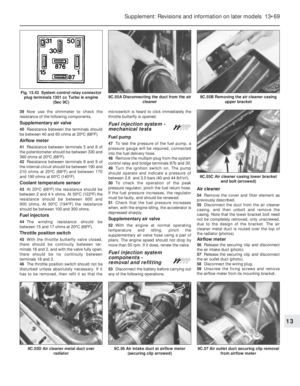 194
194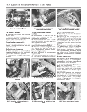 195
195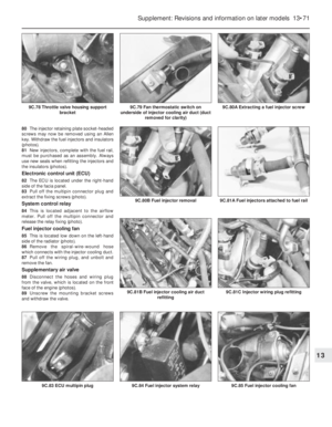 196
196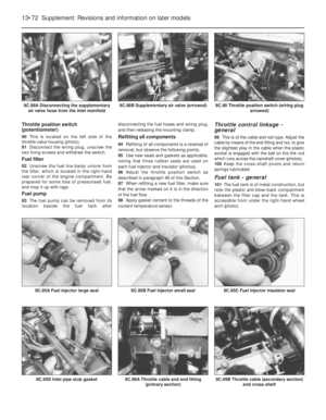 197
197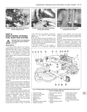 198
198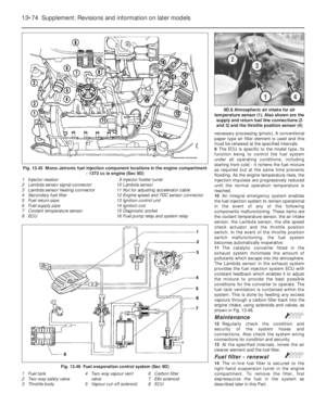 199
199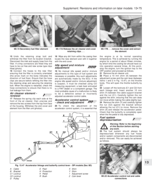 200
200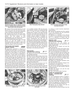 201
201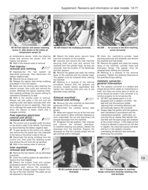 202
202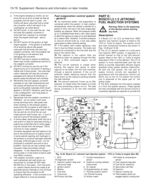 203
203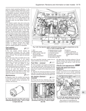 204
204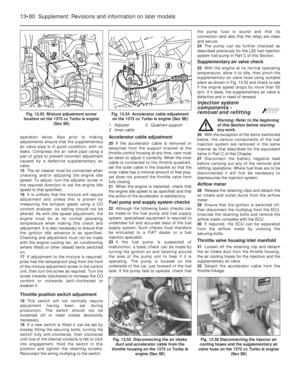 205
205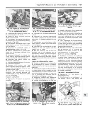 206
206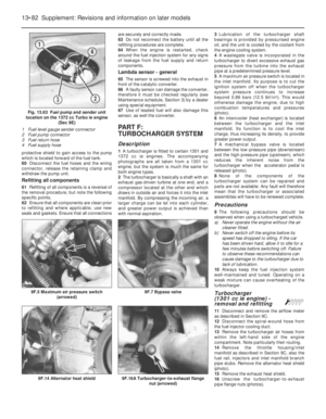 207
207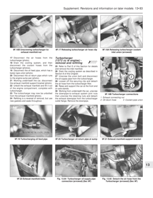 208
208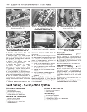 209
209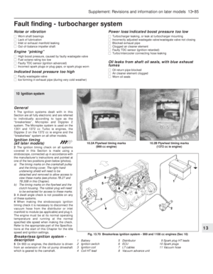 210
210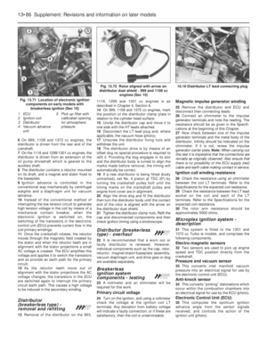 211
211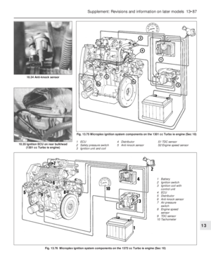 212
212 213
213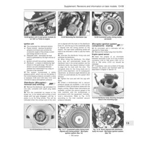 214
214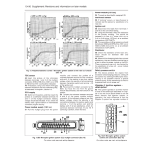 215
215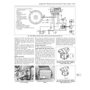 216
216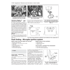 217
217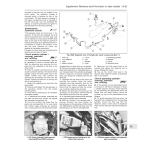 218
218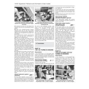 219
219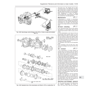 220
220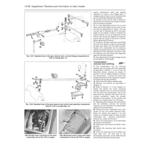 221
221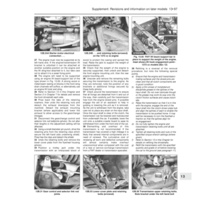 222
222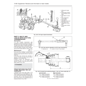 223
223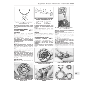 224
224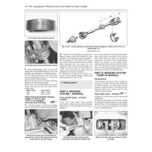 225
225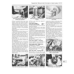 226
226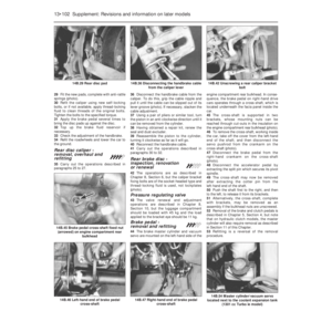 227
227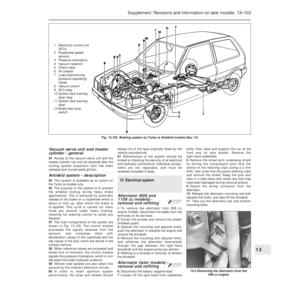 228
228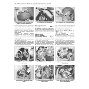 229
229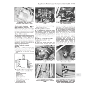 230
230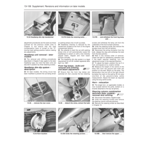 231
231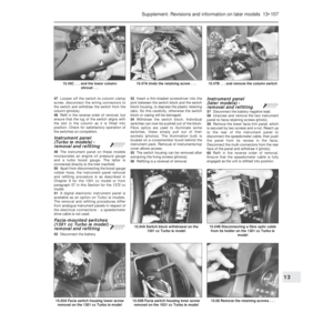 232
232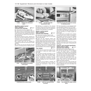 233
233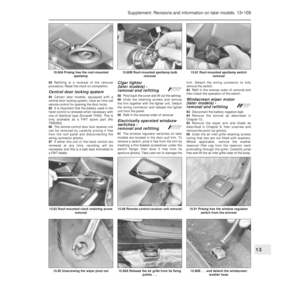 234
234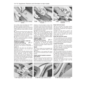 235
235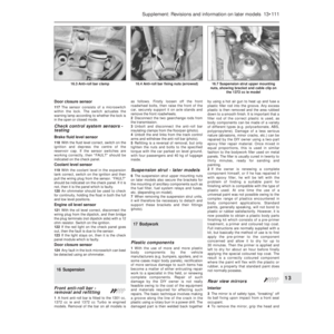 236
236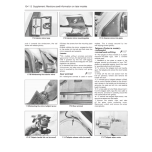 237
237 238
238 239
239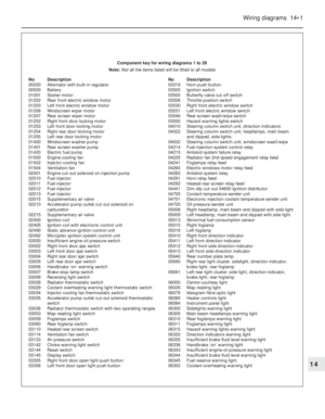 240
240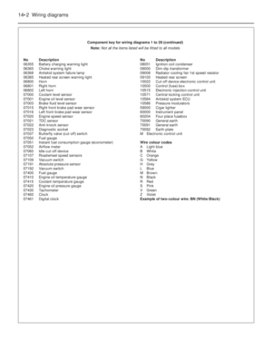 241
241 242
242 243
243 244
244 245
245 246
246 247
247 248
248 249
249 250
250 251
251 252
252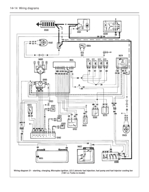 253
253 254
254 255
255 256
256 257
257 258
258 259
259 260
260 261
261 262
262 263
263 264
264 265
265 266
266 267
267 268
268 269
269 270
270 271
271 272
272 273
273 274
274 275
275 276
276 277
277 278
278 279
279 280
280 281
281 282
282 283
283 284
284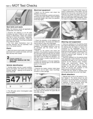 285
285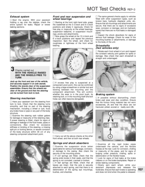 286
286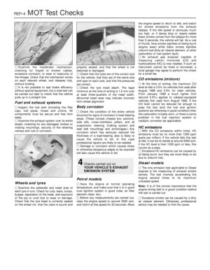 287
287 288
288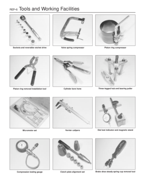 289
289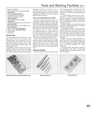 290
290 291
291 292
292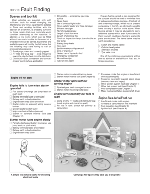 293
293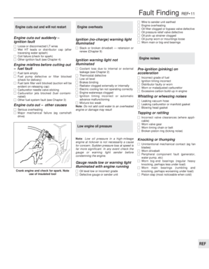 294
294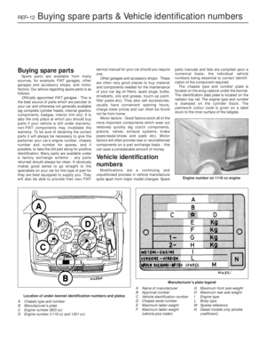 295
295 296
296 297
297 298
298 299
299 300
300 301
301 302
302