Page 169 of 303

bolts adjacent to the line of the spark plug
holes and tighten them to their specified
torque wrench setting (photo).
123Reconnect the associated fittings")
tightened, refit the five smaller (M8 x 1.25)
bolts adjacent to the line of the spark plug
holes and tighten them to their specified
torque wrench setting (photo).
123Reconnect the associated fittings to the
cylinder head in the reverse order of removal.
Ensure that the mating faces of the exhaust
manifold-to-downpipe are clean and fit a new
gasket when reconnecting.
124Ensure that all wiring connections are
cleanly and securely made.
125Top up the engine oil and coolant levels
as required on completion.
Cylinder head
(1372 cc Turbo ie engine)
- removal and refitting
#
126Proceed as described in paragraphs 102
to 125 above for the non-Turbo model, but
note the following differences.127The cylinder head cannot be removed
and refitted with the manifolds and
turbocharger fitted. It is therefore first
necessary to detach and remove the inlet
manifold, then the turbocharger and the
exhaust manifold as described in Section 9.
128The ignition distributor is mounted on the
side of the engine, not the rear end of the
cylinder head as on the “ie” engine. It is
therefore only necessary to disconnect the HT
leads from the spark plugs.
Cylinder head - inspection
and renovation¢
Note: Refer to a dealer for advice before
attempting to carry out valve grinding or seat
recutting operations. These operations may
not be possible for the DIY mechanic due to
the fitment of hardened valve seats for use
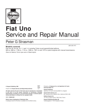
with unleaded petrol.129Use a straight-edge to check the cylinder
head gasket surface for distortion. If it
exceeds the specified tolerance, it must be
resurfaced by a FIAT dealer or automotive
engineer.
130Refer to Section 39 in Chapter 1 for the
general details on dismantling and renovating
operations on the cylinder head but note that
there is a spring seat and a flat washer fitted
between the cylinder head and the valve
springs (photos).
Crankshaft front oil seal -
removal and renewal#
131Remove the timing belt as described
earlier in this Section. Note that as mentioned
previously, the timing belt will need to be
renewed during reassembly.
132Referring to Fig. 13.18, loosen off the bolt
indicated from the timing belt rear cover.
13•44 Supplement: Revisions and information on later models
7B.130H . . . the outer spring . . .7B.130G . . . the inner spring . . .7B130F . . . locate the spring seat . . .
7B.130E Refit the flat washer . . .7B.130D . . . and drive it into position7B.130C . . . locate stem oil seal . . .
7B.130B Valve assembly - 1372 cc engine;
insert valve into guide . . .7B.130A Inlet (A) and exhaust (B) valves
and associate components - 1372 cc
engine7B.122 Tighten the smaller cylinder head
bolts to their specified torque setting
Page 170 of 303

133Drain the engine oil from the sump into a
suitable container. Disconnect the lead from
the engine oil level sensor in the sump.
134Where applicable, unscrew and remove
the bolts retaining the gear linkage mounting
bracket and the clutch housing lower cover
bolts. Remove the cover from the clutch
housing.
135Unscrew the sump retaining nuts and
bolts, then lower and remove the sump.
136Unscrew the timing belt rear cover
retaining bolts.
137Move the timing belt rear cover towards
the front of the car to gain access to the
retaining bolt and then unscrew and remove
the three oil seal housing retaining bolts.
Remove the crankshaft front oil seal housing.
138Note the orientation of the seal in its
housing prior to its removal. Support the
underside of the housing and carefully drive
the old oil seal from the housing using a
punch or a tubular drift of suitable diameter.
An alternative method is to punch or drill a
small hole in the face of the oil seal (but take
care not to drill into the housing) and insert a
self-tapping screw into the seal. Withdraw the
seal by gripping the screw with pliers and
pulling the seal from the housing. If necessary,
fit a second screw into the seal on the
opposite side to provide an even pull.
139Clean the mating faces of the housing
and the front of the crankcase using a suitable
scraper.
140Drive or press the new seal into positionin the housing in the reverse order of removal,
but ensure that it is correctly orientated as
noted during removal (photo).
141Refit the oil seal housing with a new
gasket and tighten the retaining bolts to the
specified torque setting (photos).
142Refit the sump as described later in this
Section using a new gasket. Tighten its
retaining nuts and bolts to the specified
torque. Refit the clutch cover and the gear
linkage mounting bracket.
143Fit the new timing belt, adjust its tension
and refit the crankshaft pulley as described
earlier in this Section.
144Reconnect the remaining components
that were detached during removal in the
reverse order and top up the engine oil level to
complete.
Crankshaft rear oil seal -
removal and renewal#
145If the engine is still in the car, disconnect
the battery negative lead.
146Remove the flywheel as described in the
next sub-Section.
147Punch or drill a small hole in the rear face
of the rear oil seal (but take care not to drill
into the housing) and insert a self-tapping
screw into the seal. Withdraw the seal by
gripping the screw with pliers and pulling it
from the housing. If necessary, fit a second
screw into the seal on the opposite side to
provide an even pull.
148Clean the seal housing, then locate the
Supplement: Revisions and information on later models 13•45
Fig. 13.18 Timing belt rear cover bolt
(arrowed) - 1372 cc ie and Turbo ie engines
(Sec 7B)7B.130J Compress spring and refit the split
collets7B.130I . . . and cap
7B.140 Driving a new crankshaft front oil
seal into its housing7B.141B . . . ensuring it is flush with the
face of the cylinder block7B.141A Refit the crankshaft front oil seal
housing . . .
Fig. 13.20 Removing the timing belt rear
cover on the 1372 ie and Turbo ie engines
(Sec 7B)
Fig. 13.19 Unscrew the bolts at the points
indicated to release the gear linkage
mounting bracket - 1372 cc ie and Turbo ie
engines (Sec 7B)
13
Page 171 of 303

new oil seal, ensuring that it is correctly
orientated, and drive it squarely into position.
149Refit all disturbed components.
Flywheel - removal,
inspection and refitting#
150If not already done, remove the clutch as
described in Chapter 5.
151Prevent the flywheel from turning by
jamming the ring gear teeth, or by bolting a
strap between the flywheel and the cylinder
block.
152Make alignment marks on the flywheel
and the end of the crankshaft, so that the
flywheel can be refitted in its original position.
153Unscrew the securing bolts and remove
the washer plate, then withdraw the flywheel.
Do not drop it, it is very heavy.
154With the flywheel removed, the ring gear
can be examined for wear and damage.
155If the ring gear is badly worn or has
missing teeth it should be renewed. The old
ring gear can be removed from the flywheel by
cutting a notch between two teeth with a
hacksaw and then splitting it with a cold
chisel. Wear eye protection when doing this.
156Fitting of a new ring gear requires heating
the ring to a temperature of 80ºC (176ºF). Do
not overheat, or the hard-wearing properties
will be lost. The gear has a chamfered inner
edge which should fit against the shoulder on
the flywheel. When hot enough, place the gear
in position quickly, tapping it home ifnecessary, and let it cool naturally without
quenching in any way.
157Ensure that the mating faces are clean,
then locate the flywheel on the rear of the
crankshaft, aligning the previously made
marks on the flywheel and crankshaft.
158Fit the washer plate, and insert the
securing bolts, then prevent the flywheel from
turning as described in paragraph 151 whilst
the bolts are tightened progressively to the
specified torque setting in a diagonal
sequence (photos).
159If applicable, refit the clutch as described
in Chapter 5.
Sump -
removal and refittingÁ
160Drain the engine oil from the sump as
described in Chapter 1.
161Disconnect the lead from the engine oil
level sensor in the sump.
162Unscrew and remove the bolts retaining the
gear linkage mounting bracket (where applicable)
and the clutch housing lower cover bolts.
Remove the cover from the clutch housing.
163Unscrew and remove the sump retaining
bolts and nuts and lower the sump from the
crankcase. Recover the gasket.
164Clean all traces of old gasket from the
sump, crankcase and both oil seal housing
mating surfaces.
165Commence reassembly by applying
sealing compound (FIAT No. 5882442 orequivalent) to the joints between the
crankshaft front and rear oil seal housings and
the mating face of the crankcase (photo).
166Locate the new gasket in position on the
crankcase then fit the sump. As it is fitted it
will need to be twisted to avoid fouling the oil
pump unit. Refit the retaining bolts and nuts
and tighten them to the specified torque
(photos).
167Check that the sump drain plug is refitted
and fully tightened. If the engine is in the car,
top up the engine oil level.
Oil pump - removal,
checking and refittingª
168Drain the engine oil and remove the
sump as described in the previous
sub-Section.
169Unscrew the retaining bolts then
withdraw the oil pump and intake pipe/filter
from its location within the crankcase.
Remove the gasket.
170If oil pump wear is suspected, first check
the cost and availability of new parts and the
cost of a new pump. Then examine the pump
as described below and decide whether
renewal or repair is the best course of action.
171Unscrew the three securing bolts and
remove the oil pump cover (photo). Note that
as the cover is removed, the oil pressure relief
valve components will be released.
172Recover the oil pressure relief valve,
spring and spring seat.
13•46 Supplement: Revisions and information on later models
7B.166C . . . and insert the retaining bolts7B.166B . . . refit the sump . . .7B.166A Locate the new gasket . . .
7B.165 Apply sealant to the front oil seal
housing/cylinder block joint7B.158B . . . tighten the bolts to the
specified torque7B.158A Locate the flywheel, washer plate
and bolts . . .
Page 172 of 303

173Lift the intermediate plate from the oil
pump body.
174The gears can now be removed from the
oil pump body. Inspect them for obvious signs
of wear or damage, and renew if necessary.
175Commence reassembly by lubricating
the gears with clean engine oil, and refitting
them to the casing. Note that the scribed
marks on the top faces of the gears should
face each other with the gears installed
(photo).
176Using a feeler gauge, check that the
clearance between the gears and the pump
body is within the limits given in the Specifica-
tions (photo).
177Using a straight-edge placed across the
top of the pump body and the gears, and a
feeler gauge, check that the gear endfloat is
within the limits given in the Specifications
(photo).
178If either the gear-to-body clearance, or
the gear endfloat is outside the specified
limits, both gears should be renewed.
179Locate the intermediate plate on the
pump body (photo).
180Place the pressure relief valve and spring
over the pressure relief hole in the
intermediate plate, and locate the spring seat
over the boss in the pump cover, then refit the
pump cover, ensuring that the pressure relief
valve components seat correctly (photos).
181Refit and tighten the pump cover
securing bolts.
182Thoroughly clean the mating faces of thepump and crankcase before refitting the
pump. Prime the pump by injecting clean
engine oil into it and turning it by hand.
183Fit the pump using a new gasket, then
insert the securing bolts and tighten them.
184Refit the sump and top up the engine oil
level.
Pistons/connecting rods -
removal and refitting#
185Remove the sump and the cylinder head
as described previously in this Section.
186The big-end caps and connecting rods
normally have identification marks stamped
into their sides, facing the coolant pump side
of the cylinder block. If no marks are present,
use a centre-punch to identify the bearing
caps and the connecting rods for location.187Turn the crankshaft so that No. 1
crankpin is at its lowest point, then unscrew
the nuts and tap off the bearing cap. Keep the
bearing shells in the cap and the connecting
rod if they are to be re-used, taping them in
position if necessary to avoid loss.
188Using the handle of a hammer, push the
piston and connecting rod up the bore and
withdraw it from the top of the cylinder block.
Loosely refit the cap to the connecting rod.
189Repeat the procedure given in
paragraphs 187 and 188 on No. 4 piston and
connecting rod, then turn the crank-
shaft through half a turn and repeat the
procedure on Nos 2 and 3 pistons and
connecting rods.
190The pistons and connecting rods and the
big-end bearings can be examined and if
Supplement: Revisions and information on later models 13•47
7B.176 Check gear-to-body clearance7B.175 Correct alignment of scribed marks
(arrowed) on gears7B.171 Undo the oil pump cover bolts
7B.180C . . . then fit the cover7B.180B Locate spring seat over boss
within pump cover . . .
7B.179 Refitting the intermediate plate7B.177 Checking the gear endfloat
7B.180A Locate pressure relief valve and
spring on the intermediate plate
13
Page 173 of 303

necessary renovated as described later in this
Section.
191Commence refitting as follows.
192Clean the backs of the bearing shells and
the recesses in the connecting rods and
big-end caps.
193Lubricate the cylinder bores with engine
oil.
194Fit a ring compressor to No. 1 piston, theninsert the piston and connecting rod into No. 1
cylinder. With No 1 crankpin at its lowest point,
drive the piston carefully into the cylinder with
the wooden handle of a hammer (photos).
Leave enough space between the connecting
rod and the crankshaft to allow the bearing
shell to be fitted. The piston must be fitted with
the cut-out in the piston crown on the auxiliary
shaft side of the engine, and the cylinder identi-
fication marking on the connecting rod and
big-end cap on the coolant pump side of the
engine - see Fig. 13.21.
195Slide the appropriate bearing shell into
position in the connecting rod big-end, then
pull the connecting rod firmly into position on
the crankpin (photo).
196Press the appropriate bearing shell into
position in the big-end cap (photo).
197Oil the crankpin, then fit the big-end
bearing cap with the cylinder identification
marking on the coolant pump side of the
engine, and tighten the nuts to the specified
torque setting (photos).
198Check that the crankshaft turns freely.
199Repeat the procedure in paragraphs 194
to 198 inclusive on the remaining pistons.
200Refit the cylinder head and the sump.
Pistons/connecting rods -
examination and
renovation
#
201The procedures for inspecting and
renovating the pistons and connecting rod
assemblies are in general the same as thatdescribed for the smaller engines in Sec-
tion 18 of Chapter 1. However, the following
additional points should be noted.
202When renewing a gudgeon pin, first
check the fit in the piston. It should be
possible to fit the gudgeon pin using hand
pressure, but the pin should be a tight enough
fit that it does not drop out under its own
weight. Oversize gudgeon pins are available
as spares if necessary. Use new circlips when
refitting the pistons to the connecting rods.
203Before fitting the pistons to their
connecting rods, weigh each piston and
check that their weights are all within 2.5 g of
each other. If not, the heavier pistons must be
lightened by machining metal from the
underside of the small-end bosses. This
operation must be entrusted to a FIAT dealer
or engine reconditioning specialist.
204The pistons should be fitted to the
connecting rods so that the higher, flat side of
the piston crown is on the side of the
connecting rod with the stamped cylinder
identification number, ie the gudgeon pin is
offset towards the cylinder identification
number see Fig. 13.21.
205The piston rings should be fitted with the
word “TOP” on each ring facing uppermost,
or if no marks are visible, as noted during
removal. If a stepped top compression ring is
being fitted, fit the ring with the smaller
diameter of the step uppermost. The ring end
gaps should be offset 120º from each other.
Use two or three old feeler gauges to assist
13•48 Supplement: Revisions and information on later models
7B.197B . . . and tighten the nuts to the
specified torque
Fig. 13.21 Correct orientation of piston
and connecting rod in engine - 1372 cc ie
and Turbo ie engines (Sec 7B)
1 Auxiliary shaft
2 Cylinder identification markings on
connecting rod and big-end cap
Arrow denotes direction of engine rotation
Note offset gudgeon pin
7B.197A . . . then fit the cap . . .7B.196 . . . and big-end bearing cap . . .
7B.195 Assemble the shell bearing to the
connecting rod . . .7B.194B Tapping a piston into its bore7B.194A Fitting a ring compressor to a
piston
Page 174 of 303

fitting, as during removal. Note that the
compression rings are brittle, and will snap if
expanded too far.
206If new pistons are to be fitted, they must
be selected from the grades available, after
measuring the cylinder bores. Normally, the
appropriate oversize pistons are supplied by
the dealer when the block is rebored.
207Whenever new piston rings are being
installed, the glaze on the original cylinder
bores should be removed using either
abrasive paper or a glaze-removing tool in an
electric drill. If abrasive paper is used, use
strokes at 60º to the bore centre-line, to
create a cross-hatching effect.
Engine/transmission
mountings - renewalÁ
208The engine/gearbox assembly is
suspended in the engine compartment on
three mountings, two of which are attached to
the gearbox, and one to the engine.
Right-hand mounting
209Apply the handbrake, then jack up the
front of the vehicle and support it securely on
axle stands.
210Suitable lifting tackle must now be
attached to the engine in order to support it as
the engine mounting is removed. No lifting
brackets are provided, so care must be taken
when deciding on an engine lifting point. In the
workshop, a right-angled bracket was made up
by bending a suitable piece of steel plate. The
bracket was then bolted to the engine using the
rear right-hand camshaft housing securing bolt
with suitable packing washers.
211Attach the lifting tackle to the bracket on
the engine and just take the weight of the
assembly.
212Working under the vehicle, unbolt the
engine mounting bracket from the cylinder
block, and unbolt the mounting from the
body, then withdraw the bracket/mounting
assembly.
213Unscrew the nut and through-bolt,
counter holding the bolt with a second
spanner or socket, and separate the mounting
from the bracket.
214Fit the new mounting to the bracket, and
tighten the nut to the specified torque, while
counterholding the through-bolt using a
suitable spanner or socket.
215Refit the mounting bracket to the cylinder
block, and tighten the securing bolts to the
specified torque.
216Refit the mounting to the body and
tighten the securing bolts to the specified
torque.
217Disconnect the lifting tackle from the
engine, and remove the engine lifting bracket.
218Lower the vehicle to the ground.
Left-hand mountings
219Apply the handbrake, then jack up the
front of the vehicle and support it securely on
axle stands.
220Suitable lifting tackle must now be
attached to the gearbox lifting bracket inorder to support the weight of the assembly
as the mounting is removed.
221Attach the lifting tackle to the bracket on
the gearbox, and just take the weight of the
assembly.
222Working under the vehicle, unbolt the
mounting bracket from the gearbox, and
unbolt the mounting from the body, then
withdraw the bracket/mounting assembly.
223Proceed as described in paragraphs 213
and 214.
224Refit the mounting bracket to the
gearbox, and tighten the securing bolts to the
specified torque.
225Refit the mounting to the body and
tighten the mounting bolts to the specified
torque.
226Disconnect the lifting tackle from the
engine.
227Lower the vehicle to the ground.
PART C: ENGINE REMOVAL
AND DISMANTLING
Method of removal - general
1The engine (complete with transmission) is
disconnected and lowered downwards
through the engine compartment, then
withdrawn from the front underside of the car.
1372 cc engine/
transmission - removal
and separation
#
Warning: Refer to the beginning
of Section 9 before starting any
work.
2Depressurize the fuel system as described
in Section 9 of this Chapter.
3Disconnect the battery negative lead.
4Mark the position of the hinges on the
underside of the bonnet, then with the aid of
an assistant, unscrew the hinge bolts and lift
the bonnet clear of the car. Store the bonnet
in a safe area.
5Drain the engine coolant.
6Drain the engine and transmission oils.
7Disconnect and remove the air filter.
8Disconnect the coolant hoses from the
engine, including the hose to the inlet
manifold.
9Detach the ignition coil (HT) lead from the
distributor.10Compress the retaining clip and detach
the engine idle speed actuator lead from the
SPi unit (photo).
11Disconnect the brake servo vacuum pipe
from its connector on the inlet manifold.
12Disconnect the throttle cable from the SPi
unit.
13Disconnect the engine speed sensor lead.
14Release and detach the reversing light
lead from the switch on the transmission
(photo).
15Before disconnecting the hydraulic hose
from the clutch slave cylinder, remove the
filler cap from the reservoir and place a piece
of polythene sheet over the filler neck, then
refit the cap; this will help prevent excess fluid
loss. Once disconnected, plug the hose and
its cylinder connection to prevent the ingress
of dirt into the hydraulic system.
16Disconnect the wiring connector from the
alternator.
17Position a clean rag under the fuel supply
and return hose connections to the SPi unit,
then slowly unscrew the hose clips to release
the system pressure; catch fuel leakage in the
rag and dispose of it safely. Detach the hoses
and plug them to prevent ingress of dirt and
any further fuel leakage. Position the hoses
out of the way.
18Detach the wiring connector from the
engine coolant temperature sender unit
(photo).
19Release the retaining clip and detach the
wiring connector from the throttle position
switch. Also detach the associated earth
leads from the cylinder head.
Supplement: Revisions and information on later models 13•49
7C.14 Reversing light switch and lead7C.18 Engine coolant temperature sender
and wiring connector
7C.10 Engine idle speed actuator/SPi unit
lead connection (arrowed)
13
Page 175 of 303
.
21Loosen off the front wheel bolts each
side, then raise and support the car at the
front end on")
20Release the retaining clip and detach the
wiring connector from the fuel injector
connection (photo).
21Loosen off the front wheel bolts each
side, then raise and support the car at the
front end on axle stands. When raised,
support at a height which will allow the engine
and transmission to be withdrawn from the
underside when fully disconnected. Ensure
that the vehicle is securely supported before
working underneath it.
22Unscrew the wheel bolts and remove the
front roadwheels.
23Release the retaining clips and remove
the underwing shield from the right- and
left-hand front wheel arch.24Relieve the staking, then unscrew and
remove the front hub nut using a socket and
suitable extension. Repeat the procedure on
the opposite front hub.
25Unscrew the retaining nut and disconnect
the tie-rod to steering arm balljoint using a
suitable balljoint separator tool. Repeat the
procedure on the other side.
26Note the direction of fitting, then unscrew
and remove the hub-to-strut retaining bolts
and nuts on each side.
27Unscrew and remove the anti-roll bar-
to-track control arm retaining nuts each side.
28Unscrew and remove the front brake
caliper hydraulic pipe support bracket bolt
each side.29Pull the wheel hub outwards and detach
the driveshaft from it, noting that there may be
a small amount of oil spillage as it is
withdrawn. Repeat the procedure on the
opposite side.
30Disconnect the wiring connector from the
engine oil level sensor lead.
31Unscrew the retaining nuts to detach and
remove the exhaust pipe front section or
alternatively, remove the system complete.
32Unscrew the knurled retaining nut and
detach the speedometer cable from the
transmission (photo).
33Unscrew the retaining nut and detach the
earth strap from the transmission (photo).
34Extract the split pin and detach the gear
selector rod from the transmission pin.
Disconnect the gear engagement and selector
levers from the balljoints.
35The weight of the engine will now need to
be supported from above. Connect a suitable
lift hoist and sling to the engine. When
securely connected, take the weight of the
engine/transmission unit so that the tension is
relieved from the mountings.
36Unscrew and remove the engine and
transmission support mounting bolts at the
points indicated (photos).
37The engine/transmission unit should now
be ready for removal from the vehicle. Check
that all of the associated connections and
13•50 Supplement: Revisions and information on later models
Fig. 13.22 The underwing
shield retaining clips (arrowed)
on the 1372 cc ie and Turbo ie
engines (Sec 7C)Fig. 13.25 Gear engagement
and selector lever balljoints
(arrowed) on the 1372 cc ie and
Turbo ie engines (Sec 7C)Fig. 13.23 Engine oil level
sensor wiring connector
(arrowed) on the 1372 cc ie and
Turbo ie engines (Sec 7C)Fig. 13.24 Disconnect the gear
selector rod at the connection
indicated on the 1372 cc ie and
Turbo ie engines (Sec 7C)
7C.33 Disconnect the transmission earth
strap7C.32 Disconnecting the speedometer
drive cable from the transmission7C.20 Fuel injector wiring connection
7C.36B Transmission rear mounting7C.36A Engine right-hand mounting
Page 176 of 303

fittings are disconnected from the engine and
transmission and positioned out of the way.
Enlist the aid of an assistant to help steady
and guide the power unit down through the
engine compartment as it is removed, If
available, position a suitable engine trolley or
crawler board under the engine/transmission
so that when lowered, the power unit can be
withdrawn from the front end of the vehicle
and moved to the area where it is to be
cleaned and dismantled.
38Carefully lower the engine and
transmission unit, ensuring that no fittings
become snagged. Detach the hoist and
withdraw the power unit from under the
vehicle.
39To separate the engine from the
transmission, unbolt and remove the starter
motor, then unscrew the retaining bolts and
withdraw the transmission from the engine. As
it is withdrawn, do not allow the weight of the
engine or transmission to be taken by the
input shaft.
40To remove the clutch unit, refer to
Chapter 5 for details.
1372 cc Turbo ie
engine/transmission -
removal and separation
#
41The engine and transmission removal and
refitting details for Turbo-engined models are
similar to those described for the non-Turbo
models in the previous sub-Section, but the
following differences should be noted.
42To provide access for the disconnection
of the turbo and related components, first
remove the inlet manifold. Removal of the inlet
manifold and the turbocharger is described in
Section 9 of this Chapter.
43The ignition distributor on the Turbo
engine is driven from the auxiliary shaft and is
mounted at the front of the engine, towards
the timing cover end.
44The right-hand driveshaft has a steady
bearing and this will need to be unbolted and
detached.
Engine dismantling - general
45Refer to Chapter 1, Section 14 for details.
Auxiliary shaft - removal,
inspection and refitting #
46Remove the engine and transmission from
the vehicle as described previously in this
Section part.
47Drain the engine oil and remove the sump
as described in Part B of this Section.
48Remove the oil pump as described in Part
B of this Section.
49Remove the timing belt and the auxiliary
shaft sprocket as described in Part B of this
Section.
50Unscrew the three retaining bolts and
remove the auxiliary shaft cover. Remove the
gasket.
51Withdraw the auxiliary shaft from the
cylinder block.
52Examine the shaft and its bearing bushes
in the cylinder block for signs of excessive
wear and/or damage and renew it if
necessary. Bush renewal is described in
paragraph 79 in this Section.
53The cover gasket and the oil seal should
always be renewed whenever the cover is
removed. To renew the seal, support the
cover on blocks of wood and drive out the old
seal using a suitable drift inserted in the
cut-out in the back of the cover. Clean the
seal location in the housing. Drive the new
seal into place using a suitable metal tube or
socket (photo). The sealing lip must face
towards the cylinder block. Smear the sealing
lips with clean engine oil before installation.
54Commence refitting by lubricating theauxiliary shaft journals with clean engine oil,
then insert the shaft into the cylinder block
(photo).
55Refit the auxiliary shaft cover, using a new
gasket, and tighten the securing bolts
(photos).
56Refit the auxiliary shaft sprocket, timing
belt, cover and crankshaft pulley as described
in Part B of this Section.
57Refit the engine and transmission with
reference to Part D of this Section.
Engine -
complete dismantling#
Warning: Refer to the beginning
of Section 9 before starting any
work.
58Detach and remove the following ancillary
items. Where applicable, refer to the
appropriate Chapter or Section within this
Chapter for more detailed removal instructions.
Engine oil dipstick
Ignition distributor and HT leads
Fuel pump
Alternator
Oil filter
Oil vapour recovery unit
Inlet and exhaust manifolds and associated
fuel injection components (as applicable)
Clutch unit
59Refer to Part B of this Section for details
and remove the timing cover and drivebelt.
60Refer to Part B of this Section for details
and remove the cylinder head unit.
Supplement: Revisions and information on later models 13•51
7C.54 Inserting the auxiliary shaft into the
cylinder block (rear timing belt cover
removed)7C.53 Driving a new oil seal into the
auxiliary shaft cover7C.36C Transmission front mounting
7C.55B . . . and tighten the securing bolts7C.55A Refit the auxiliary shaft cover with
a new gasket . . .
13
 1
1 2
2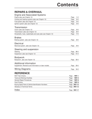 3
3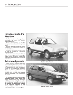 4
4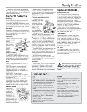 5
5 6
6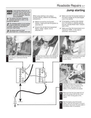 7
7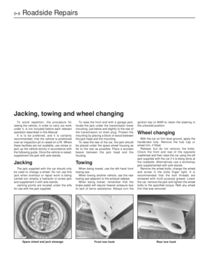 8
8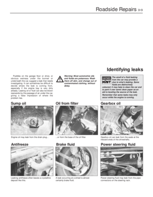 9
9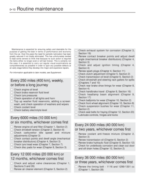 10
10 11
11 12
12 13
13 14
14 15
15 16
16 17
17 18
18 19
19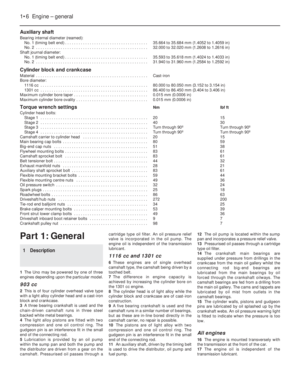 20
20 21
21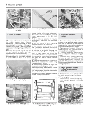 22
22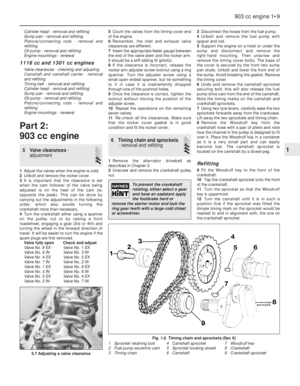 23
23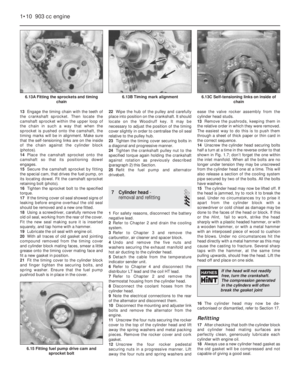 24
24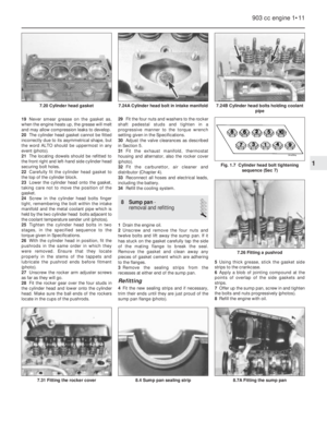 25
25 26
26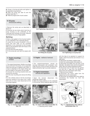 27
27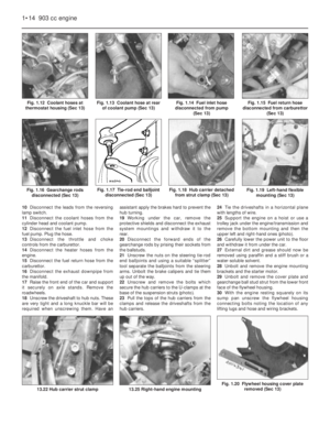 28
28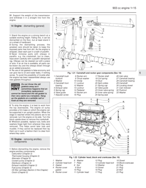 29
29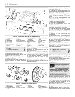 30
30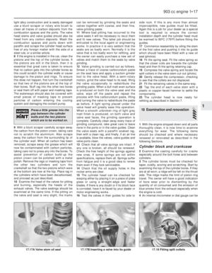 31
31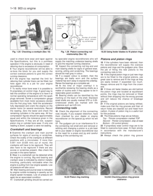 32
32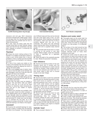 33
33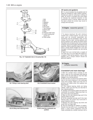 34
34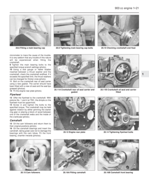 35
35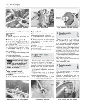 36
36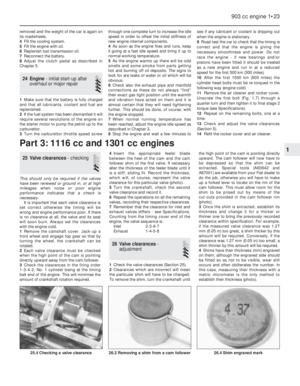 37
37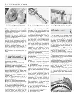 38
38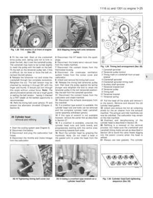 39
39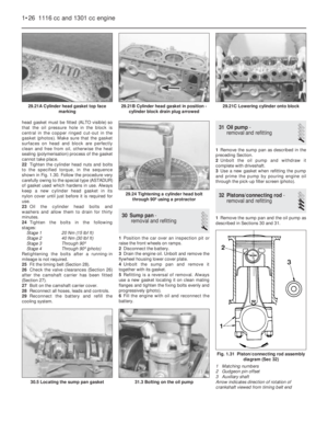 40
40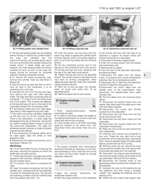 41
41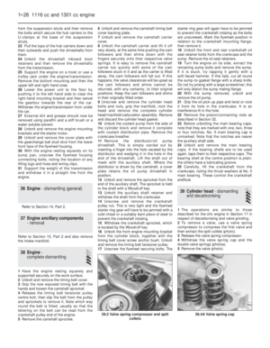 42
42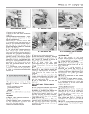 43
43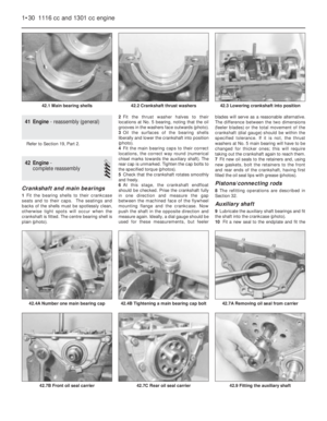 44
44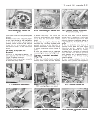 45
45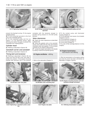 46
46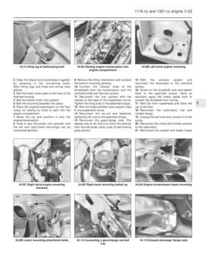 47
47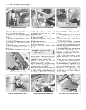 48
48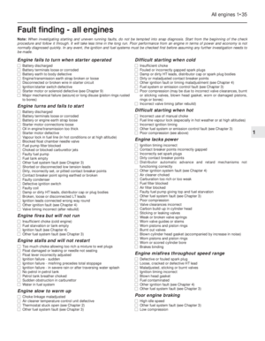 49
49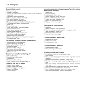 50
50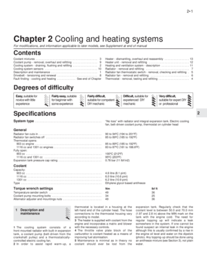 51
51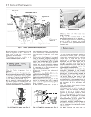 52
52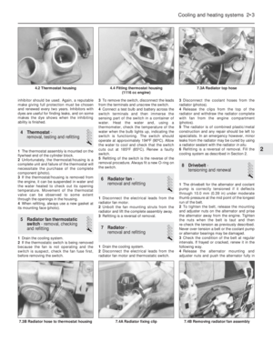 53
53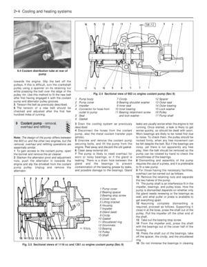 54
54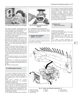 55
55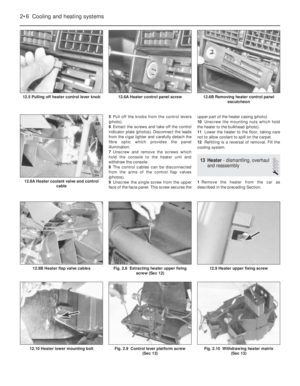 56
56 57
57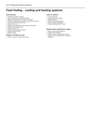 58
58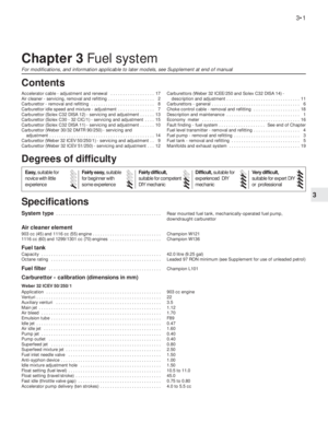 59
59 60
60 61
61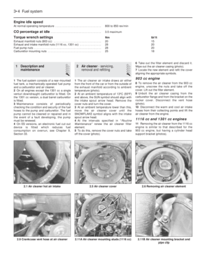 62
62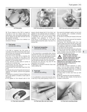 63
63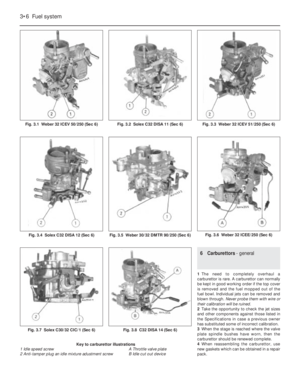 64
64 65
65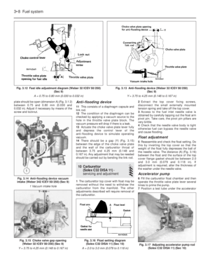 66
66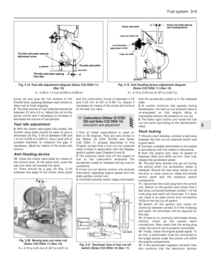 67
67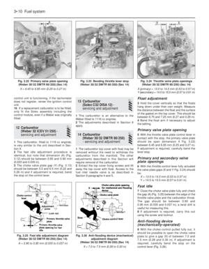 68
68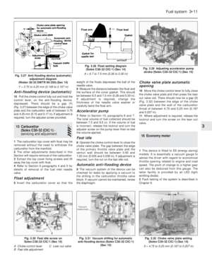 69
69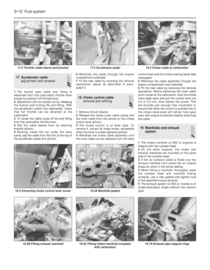 70
70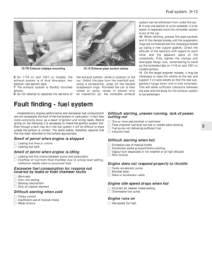 71
71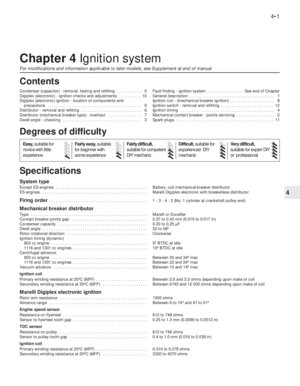 72
72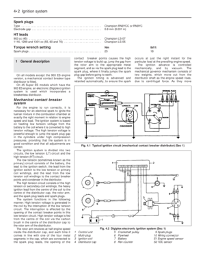 73
73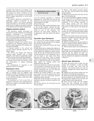 74
74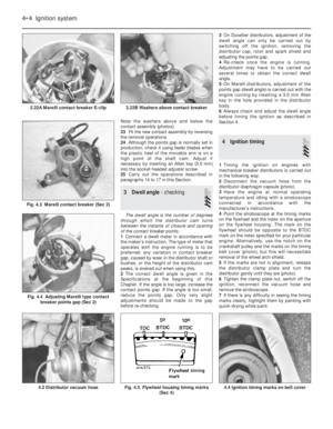 75
75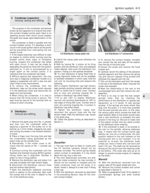 76
76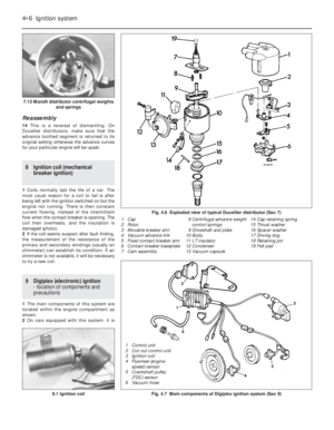 77
77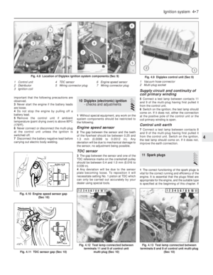 78
78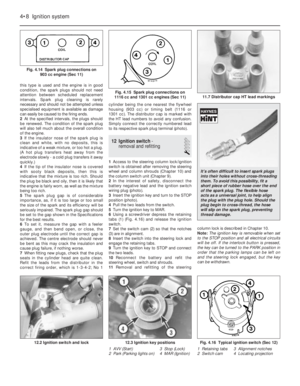 79
79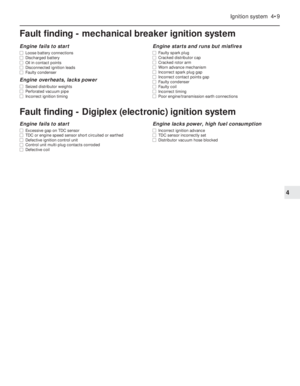 80
80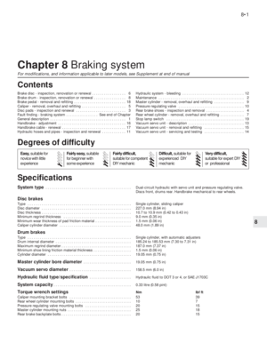 81
81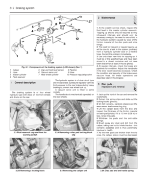 82
82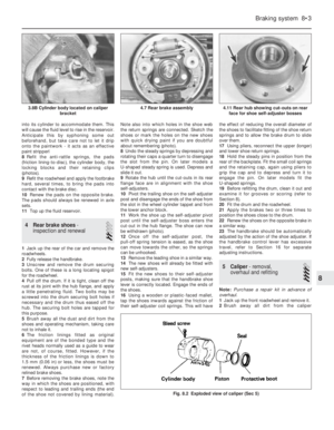 83
83 84
84 85
85 86
86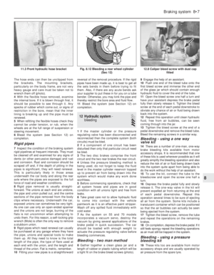 87
87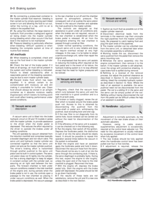 88
88 89
89 90
90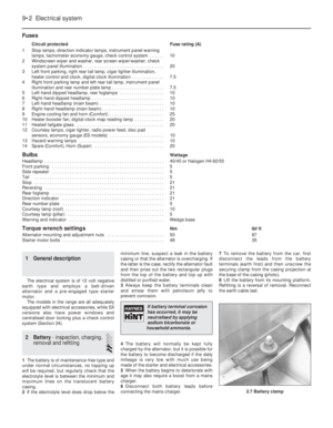 91
91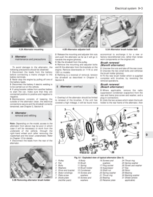 92
92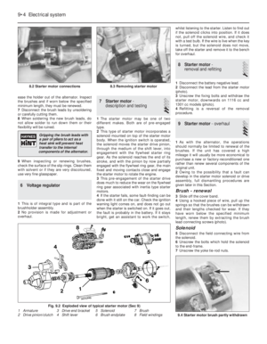 93
93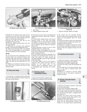 94
94 95
95 96
96 97
97 98
98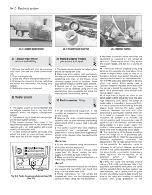 99
99 100
100 101
101 102
102 103
103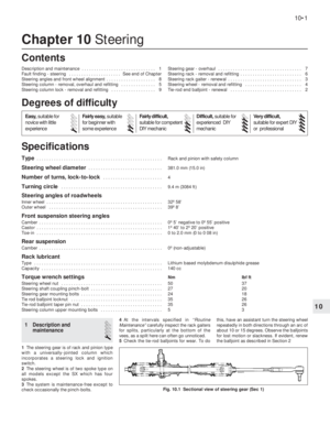 104
104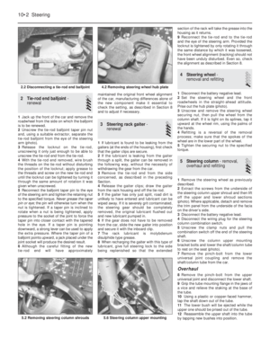 105
105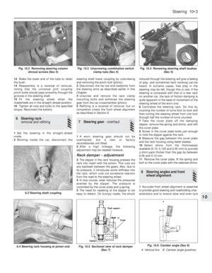 106
106 107
107 108
108 109
109 110
110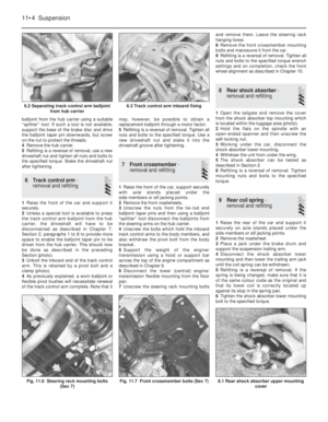 111
111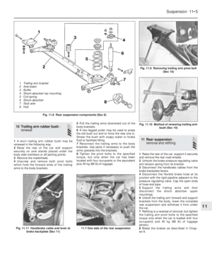 112
112 113
113 114
114 115
115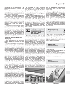 116
116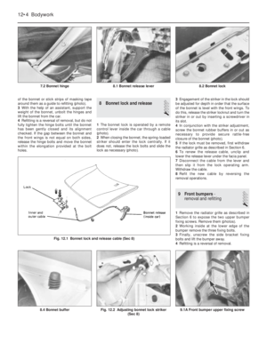 117
117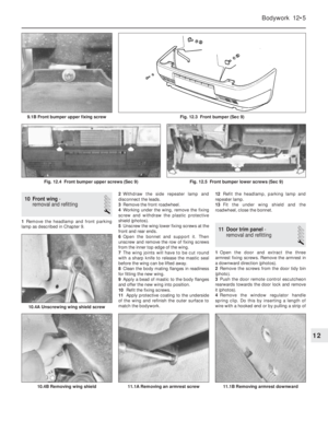 118
118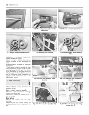 119
119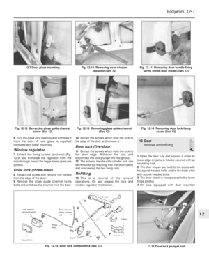 120
120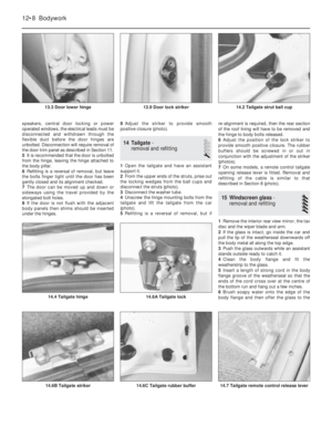 121
121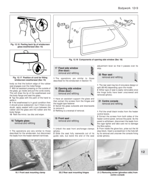 122
122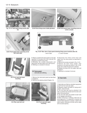 123
123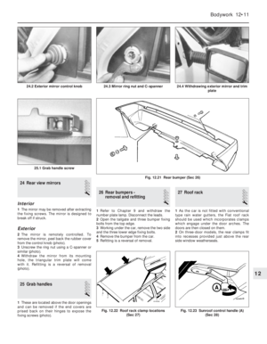 124
124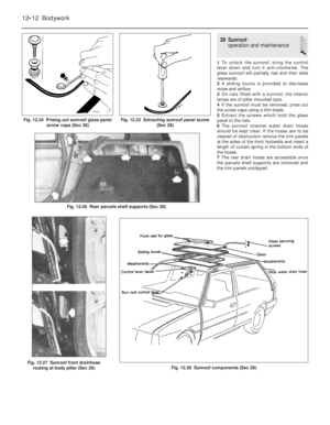 125
125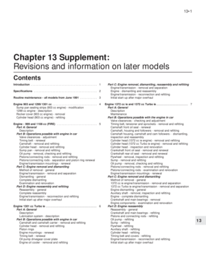 126
126 127
127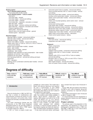 128
128 129
129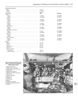 130
130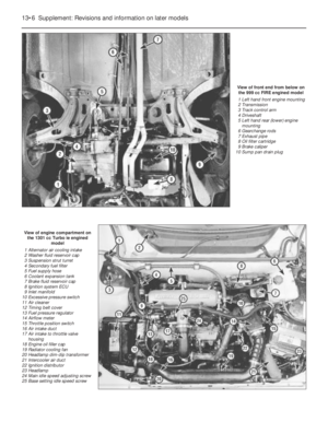 131
131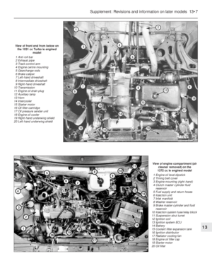 132
132 133
133 134
134 135
135 136
136 137
137 138
138 139
139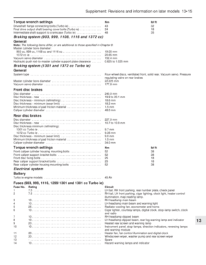 140
140 141
141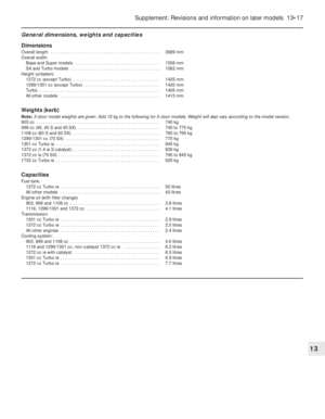 142
142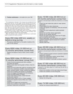 143
143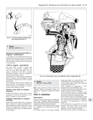 144
144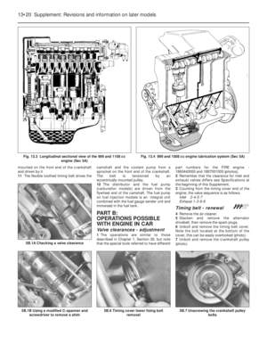 145
145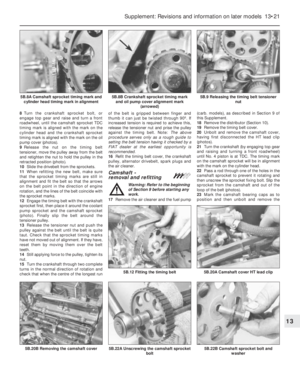 146
146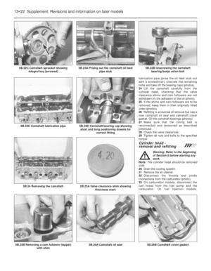 147
147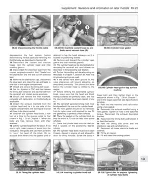 148
148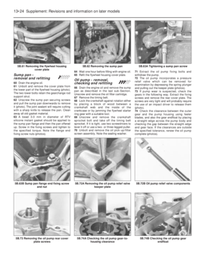 149
149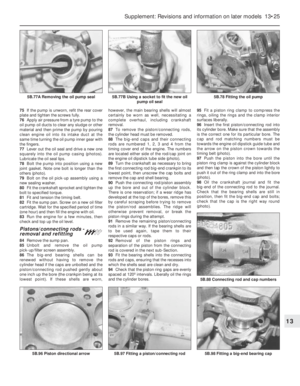 150
150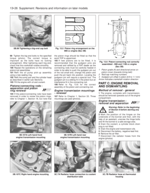 151
151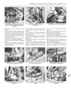 152
152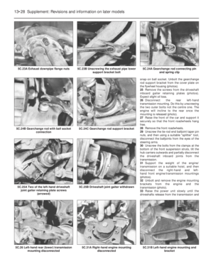 153
153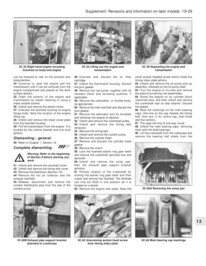 154
154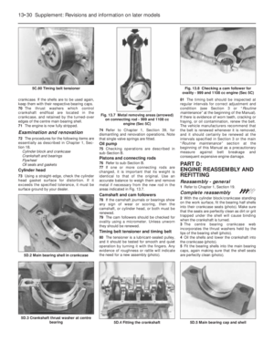 155
155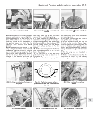 156
156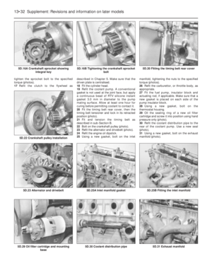 157
157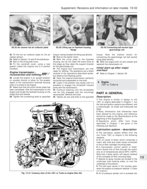 158
158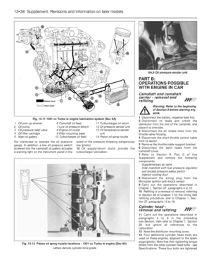 159
159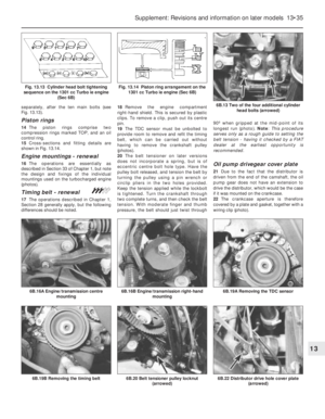 160
160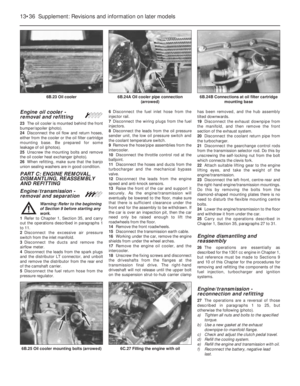 161
161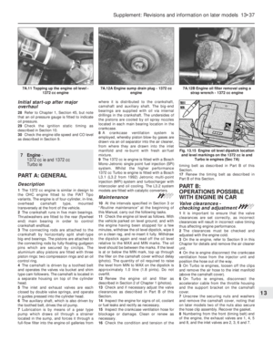 162
162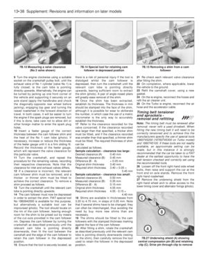 163
163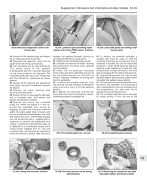 164
164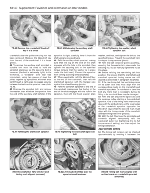 165
165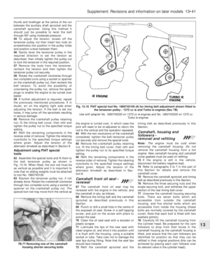 166
166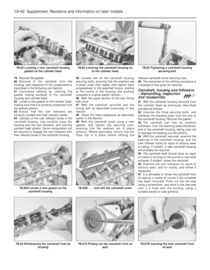 167
167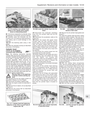 168
168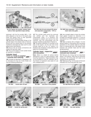 169
169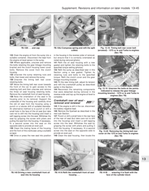 170
170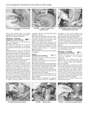 171
171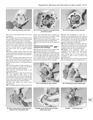 172
172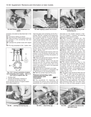 173
173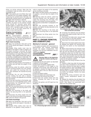 174
174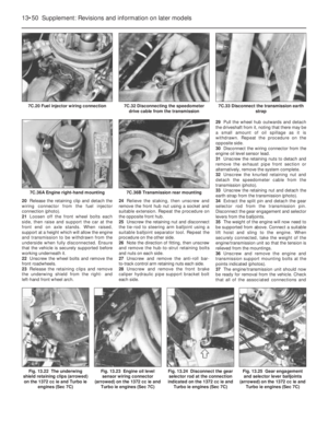 175
175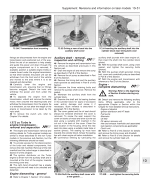 176
176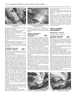 177
177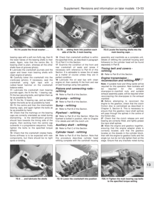 178
178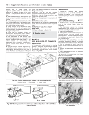 179
179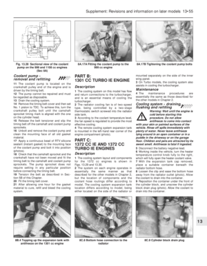 180
180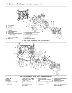 181
181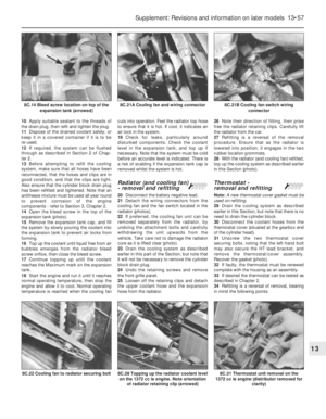 182
182 183
183 184
184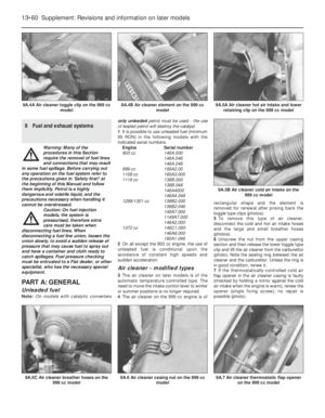 185
185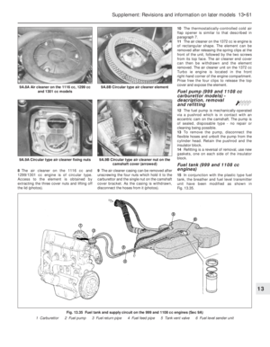 186
186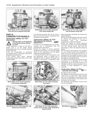 187
187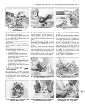 188
188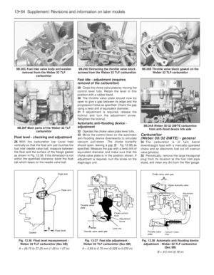 189
189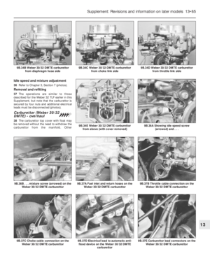 190
190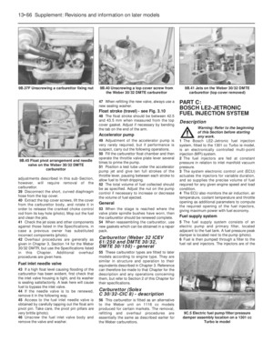 191
191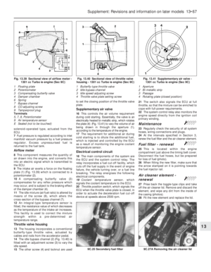 192
192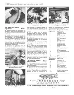 193
193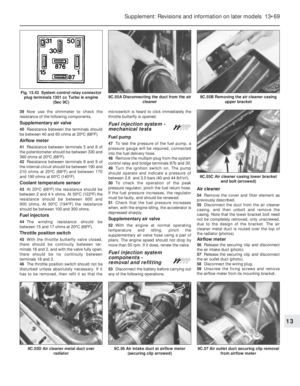 194
194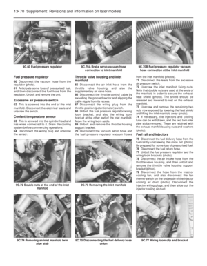 195
195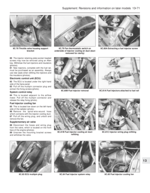 196
196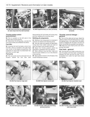 197
197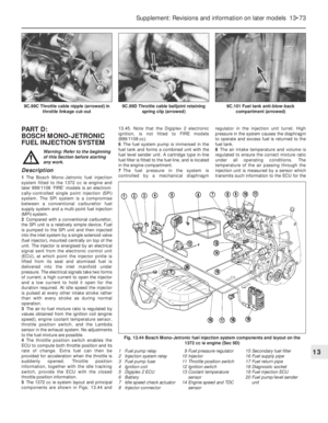 198
198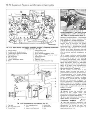 199
199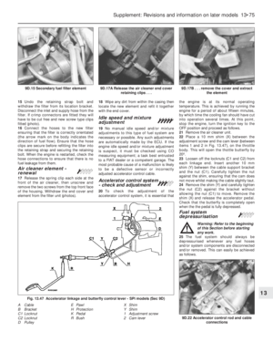 200
200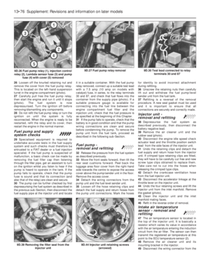 201
201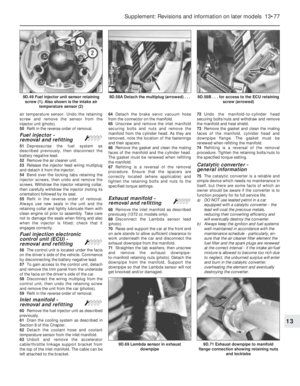 202
202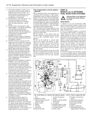 203
203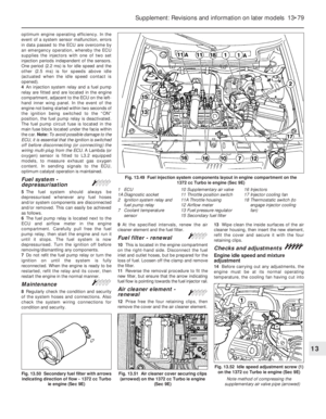 204
204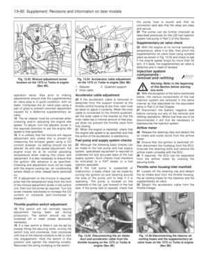 205
205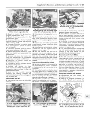 206
206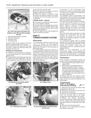 207
207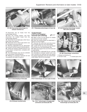 208
208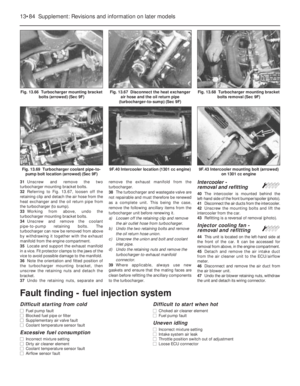 209
209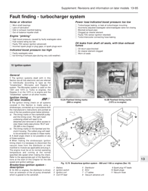 210
210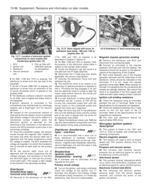 211
211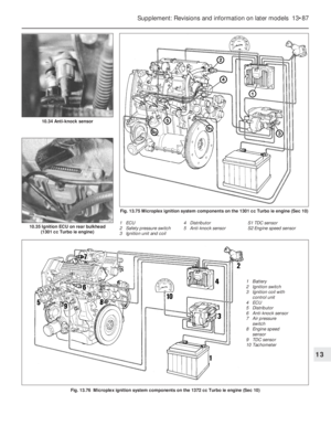 212
212 213
213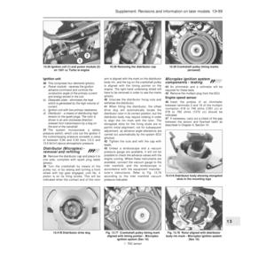 214
214 215
215 216
216 217
217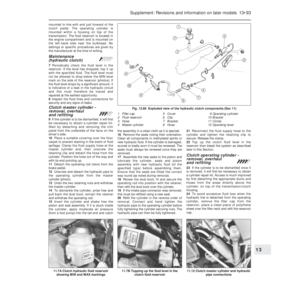 218
218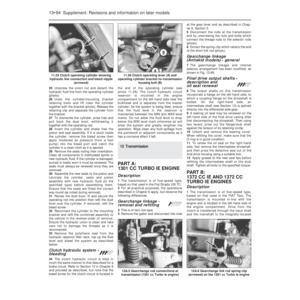 219
219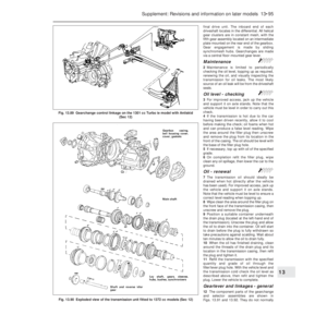 220
220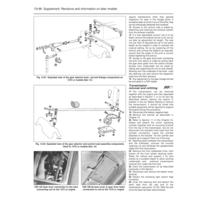 221
221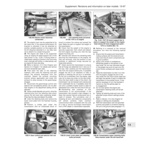 222
222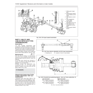 223
223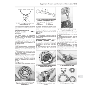 224
224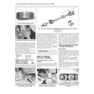 225
225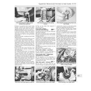 226
226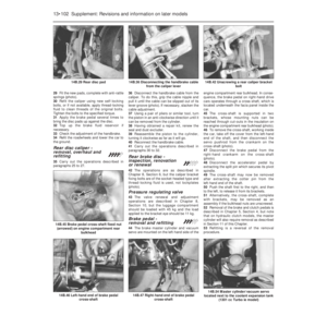 227
227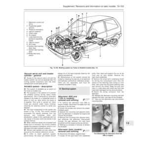 228
228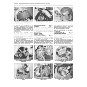 229
229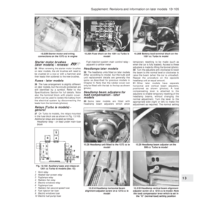 230
230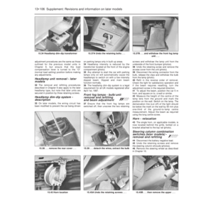 231
231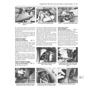 232
232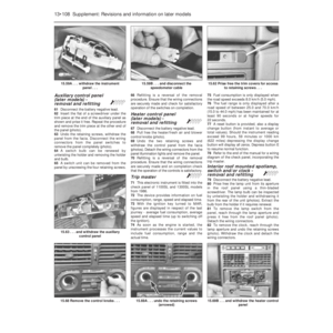 233
233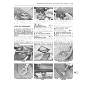 234
234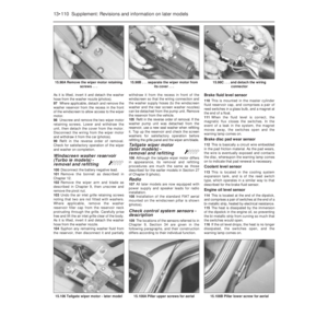 235
235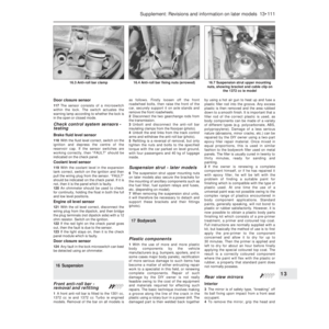 236
236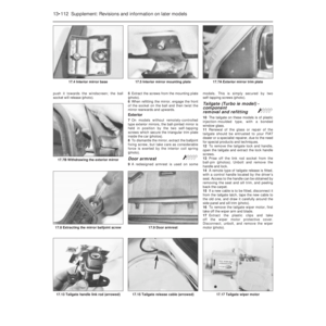 237
237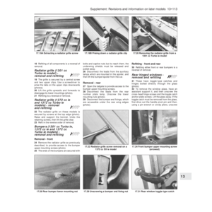 238
238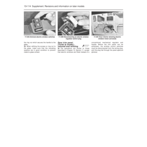 239
239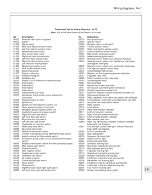 240
240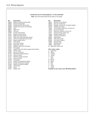 241
241 242
242 243
243 244
244 245
245 246
246 247
247 248
248 249
249 250
250 251
251 252
252 253
253 254
254 255
255 256
256 257
257 258
258 259
259 260
260 261
261 262
262 263
263 264
264 265
265 266
266 267
267 268
268 269
269 270
270 271
271 272
272 273
273 274
274 275
275 276
276 277
277 278
278 279
279 280
280 281
281 282
282 283
283 284
284 285
285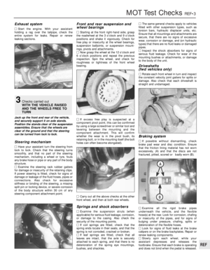 286
286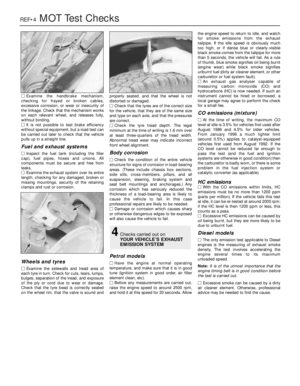 287
287 288
288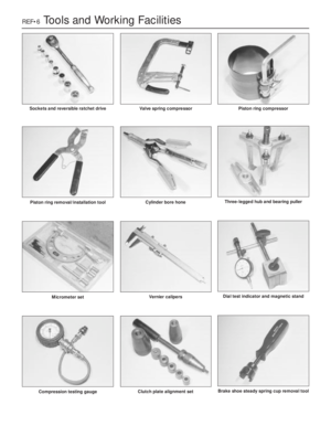 289
289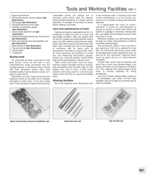 290
290 291
291 292
292 293
293 294
294 295
295 296
296 297
297 298
298 299
299 300
300 301
301 302
302