Page 217 of 303

Á
1The method of adjusting the clutch has
been revised.
2Fully depress the clutch pedal two or three
times.
3Using a suitable measuring stick plac")
11 Clutch
Clutch pedal - adjustment
(cable clutch)
Á
1The method of adjusting the clutch has
been revised.
2Fully depress the clutch pedal two or three
times.
3Using a suitable measuring stick placed in
contact with the floor panel (carpet peeled
back), measure dimension “X” in Fig. 13.87.
This dimension must be taken between the
centre of the pedal pad and the floor, first withthe pedal in the fully depressed position, and
then in the fully released position.
4The dimension measured should fall within
the range quoted in the Specifications for this
Supplement.
5Any adjustment which may be required
should be carried out by slackening the
locknut on the cable at the release lever (on
top of the gearbox) and turning the adjusting
nut. Tighten the locknut on completion.
Hydraulic clutch - description
6Some later models are fitted with an
hydraulically operated clutch in place of the
cable operated type. The main components of
the system are a master cylinder, with
separate hydraulic fluid reservoir, and the
operating cylinder. The master cylinder is
Distributor (Digiplex Z) -
removal and refitting#
70Proceed as described in paragraphs 14
to 21. When refitting the distributor, ensure that
the engine is still set at the TDC position. Engage
the rotor arm into position on the shaft so that its
lug engages in the slot in the top end of the drive
spindle. Align the rotor arm with the reference
slot on the edge of the distributor housing as
shown in Fig. 13.85, then fit the distributor into
position and secure with the retaining nuts
(photo). As previously mentioned, the fine timing
is made automatically through the ECU.
Spark plugs and HT leads -
general
71Copper-cored spark plugs are now fitted
to all models. The recommended types are
given in the Specifications Section of this
Supplement.72The HT lead connection sequence to the
distributor cap on the 999 and 1108 cc
engines is shown in Fig. 13.86. That for the
1301 cc Turbo ie is as shown (photo).
13•92 Supplement: Revisions and information on later models
Fig. 13.87 Clutch pedal adjustment
diagram - cable clutch (Sec 11)
For dimension “X” , refer to Specifications
Fig. 13.86 HT lead connections on distributor cap of the 999 and 1108 cc engines (Sec 10)
Fig. 13.85 Rotor arm must align with
slot (1) in distributor housing when refitting
distributor - Digiplex 2 ignition system
(Sec 10)
10.72 HT lead connecting sequence on the
1301 cc Turbo ie engine10.70 Ignition distributor and HT lead
connections on the 1372 cc ie engine
Fault finding - Microplex ignition system
Starter motor turns but engine will not start
m mExcessive TDC sensor gap
m mEngine speed or TDC sensors short-circuited
m mFaulty ECU
m mECU multipin contacts corroded
m mDefective ignition coil
m mDefective ignition switch
m mECU terminal 8 cable faulty
Engine firing on three cylinders
m
mFaulty spark plug
m mDistributor cap cracked
m mFaulty HT cable
Loss of power, excessive fuel consumption
m
mTDC sensor incorrectly located
m mFault in ECU advance angle facility
Page 218 of 303

mounted in-line with and just forward of the
clutch pedal. The operating cylinder is
mounted within a housing on top of the
transmission. The fluid reservoir is located in
the engine compartment and is mounted on
the left-hand side near the bulkhead. No
settings or specific procedures are given by
the manufacturer at the time of writing.
Maintenance
(hydraulic clutch)Á
7Periodically check the fluid level in the
reservoir. If the level has dropped, top it up
with the specified fluid. The fluid level must
not be allowed to drop below the MIN level
mark on the side of the reservoir (photos). If
the fluid level drops by a significant amount, it
is indicative of a leak in the hydraulic circuit
and this must therefore be traced and
repaired at the earliest opportunity.
8Inspect the fluid lines and connections for
security and any signs of leaks.
Clutch master cylinder -
removal, overhaul
and refitting
#
9If the cylinder is to be dismantled, it will first
be necessary to obtain a cylinder repair kit.
Start by detaching and removing the trim
panel from the underside of the facia on the
driver’s side.
10Place a suitable covering over the floor
carpet to prevent staining in the event of fluid
spillage. Clamp the fluid supply hose at the
master cylinder end, then unscrew the
retaining clip and detach the hose from the
cylinder. Position the hose out of the way and
with its end pointing up.
11Detach the operating rod clevis from the
brake pedal.
12Unscrew and detach the hydraulic pipe to
the operating cylinder from the master
cylinder (photo).
13Undo the two retaining nuts and withdraw
the master cylinder.
14To dismantle the cylinder, prise free and
pull back the dust boot, extract the retainer
and withdraw the operating rod.
15Invert the cylinder and shake free the
piston and seal assembly. If it is stuck inside
the cylinder, apply moderate air pressure
(from a foot pump) into the tail end and catchthe assembly in a clean cloth as it is ejected.
16Remove the seals noting their orientation.
Clean all components in methylated spirits or
new hydraulic fluid. If the cylinder is damaged,
scored or badly worn it must be renewed. The
seals must always be renewed once they are
removed.
17Assemble the new seals to the piston and
lubricate the cylinder, seals and piston
assembly with new hydraulic fluid (of the
specified type) before assembling them.
Ensure that the seals are fitted the correct
way round (as noted during removal).
18Renew the dust boot, fit and secure the
operating rod into position with the retainer,
then refit the dust boot over the cylinder.
19If the intake pipe connector was removed,
this must be refitted using a new seal.
20Refit the cylinder in the reverse order of
removal. Connect and hand tighten the
hydraulic pipe to the operating cylinder before
fully tightening the cylinder securing nuts. The
hydraulic pipe can then be fully tightened.21Reconnect the fluid supply hose to the
cylinder and tighten the retaining clip to
secure. Release the clamp.
22Top up the clutch fluid level in the
reservoir then bleed the system as described
later in this Section.
Clutch operating cylinder -
removal, overhaul
and refitting
¢
23If the cylinder is to be dismantled once it
is removed, it will first be necessary to obtain
a cylinder repair kit. Access is much improved
by first detaching the appropriate ducts and
hoses from the areas directly above the
cylinder, on top of the transmission/clutch
housing.
24To avoid excessive fluid loss when the
hydraulic line is detached from the operating
cylinder, remove the filler cap from the
reservoir, place a clean piece of polythene
sheet over the filler neck and refit the reservoir
cap.
Supplement: Revisions and information on later models 13•93
Fig. 13.88 Exploded view of the hydraulic clutch components (Sec 11)
1 Filler cap
2 Fluid reservoir
3 Hose
4 Master cylinder5 Cover
6 Clip
7 Bracket
8 Hose9 Operating cylinder
10 Bracket
11 Circlip
12 Operating lever
11.12 Clutch master cylinder and hydraulic
pipe connections11.7B Topping up the fluid level in the
clutch fluid reservoir11.7A Clutch hydraulic fluid reservoir
showing MIN and MAX markings
13
Page 219 of 303
.
26Undo the cylinder/mounting bracket
retaining bolts and lift clear the cylinder
together with the brac")
25Unscrew the union nut and detach the
hydraulic fluid line from the operating cylinder
(photo).
26Undo the cylinder/mounting bracket
retaining bolts and lift clear the cylinder
together with the bracket (photo). Release the
retaining clip and separate the cylinder from
the bracket.
27To dismantle the cylinder, prise free and
pull back the dust boot, withdrawing it
together with the operating rod.
28Invert the cylinder and shake free the
piston and seal assembly. If it is stuck inside
the cylinder, remove the bleed screw then
apply moderate air pressure (from a foot
pump) into the bleed port and catch the
cylinder in a clean cloth as it is ejected.
29Remove the seals noting their orientation.
Clean all components in methylated spirits or
new hydraulic fluid. If the cylinder is damaged,
scored or badly worn it must be renewed. The
seals must always be renewed once they are
removed.
30Assemble the new seals to the piston and
lubricate the cylinder, seals and piston
assembly with new hydraulic fluid (of the
specified type) before assembling them.
Ensure that the seals are fitted the correct
way round (as noted during removal).
31Renew the dust boot, fit and secure the
operating rod into position then refit the dust
boot over the cylinder. If removed, refit the
bleed screw.
32Reconnect the cylinder to the mounting
bracket and refit the combined assembly to
the vehicle in the reverse order of removal.
Ensure the hydraulic union is clean and take
care not to damage the threads as it is
reconnected.
33Remove the polythene seal from the
hydraulic reservoir filler neck, top up the fluid
level and bleed the system as described
below.
Clutch hydraulic system -
bleeding#
34The clutch hydraulic circuit is bled in
much the same manner to that described for a
brake circuit. Refer to Section 12 in Chapter 8
and proceed as described, but note that the
bleed screw for the clutch circuit is located inthe end of the operating cylinder (see
photo 11.25). The clutch hydraulic circuit
reservoir is mounted in the engine
compartment on the left-hand side near the
bulkhead and is separate from the master
cylinder. As the system is being bled, ensure
that the fluid level in the reservoir is
maintained between the MIN and MAX level
marks. Do not allow the fluid level to drop
below the MIN level mark otherwise air will
enter the system and greatly lengthen the
operation. Wipe clean any fluid spillage from
the paintwork or adjacent components as it
has a corrosive effect if left.
12 Transmission
PART A:
1301 CC TURBO IE ENGINE
Description
1The transmission is of five-speed type,
based on that used in the Fiat Strada 105 TC.
2For all practical purposes, the operations
described in Chapter 6 apply, but observe the
following differences.
Gearchange linkage -
removal and refitting Á
3This is of two-rod type.
4Remove the gaiter and disconnect the rodsat the gear lever end as described in Chap-
ter 6, Section 3.
5Disconnect the rods at the transmission
end by unscrewing the nuts and bolts which
connect the linkage rods to the selector rods
(photo).
6Extract the spring clip which retains the end
of the short link rod (photo).
Gearchange linkage
(Antiskid models) - general
7The gearchange linkage and internal
selector arrangement has been modified, as
shown in Fig. 13.89.
Final drive output shafts -
description and
oil seal renewal
#
8The output shafts on this transmission
incorporate a flange on the left-hand side, to
which a coupling flange on the driveshaft is
bolted. On the right-hand side, an
intermediate shaft (see Section 13) is splined
directly into the differential side gear.
9A leaking oil seal may be renewed on the
left-hand side of the final drive casing after
first disconnecting the driveshaft. Then using
two levers, prise out the flange/stub shaft
against the tension of its retaining circlip.
10Unbolt and remove the bearing cover.
When refitting the cover, make sure that the
O-ring is in good condition.
11To renew the oil seal on the right-hand
side, first remove the intermediate driveshaft,
and then prise the defective seal out of the
final drive housing using a suitable tool.
12Apply grease to the new seal lips before
refitting the intermediate shaft or the stub
shaft. Tighten all bolts to the specified torque.
PART B:
1372 CC IE AND 1372 CC
TURBO IE ENGINES
Description
1The transmission is of five-speed type,
based on that used in the FIAT Tipo. The
transmission is mounted in-line with the
engine and is located in the left-hand side of
the engine compartment. Drive from the
clutch is transferred through the input shaft
and the mainshaft to the integrally-located
13•94 Supplement: Revisions and information on later models
12A.6 Gearchange link rod spring clip
(arrowed) on the 1301 cc Turbo ie engine12A.5 Gearchange rod connections at
transmission (1301 cc Turbo ie engine)
11.26 Clutch operating lever (A) and
operating cylinder bracket-to-transmission
housing bolt (B)11.25 Clutch operating cylinder showing
hydraulic line connection and bleed nipple
(arrowed)
Page 220 of 303

final drive unit. The inboard end of each
driveshaft locates in the differential. All helical
gear clusters are in constant mesh, with the
fifth gear assembly located on an intermediate
plate mounted on the rear end of the gearbox.
Gear engagement is made by sliding
synchromesh hubs. Gearchanges are made
via a central floor-mounted gear lever.
MaintenanceÁ
2Maintenance is limited to periodically
checking the oil level, topping up as required,
renewing the oil, and visually inspecting the
transmission for oil leaks. The most likely
source of an oil leak will be from the driveshaft
seals.
Oil level - checkingÁ
3For improved access, jack up the vehicle
and support it on axle stands. Note that the
vehicle must be level in order to carry out this
check.
4If the transmission is hot due to the car
having been driven recently, allow it to cool
before making the check; oil foams when hot
and can produce a false level reading. Wipe
the area around the filler plug then unscrew
and remove the plug from its location in the
front of the casing. The oil should be level with
the base of the filler plug hole.
5If necessary, top up with oil of the specified
grade.
6On completion refit the filler plug, wipe
clean any oil spillage, then lower the car to the
ground.
Oil - renewalÁ
7The transmission oil should ideally be
drained when hot (directly after the vehicle
has been used). For improved access, jack up
the vehicle and support it on axle stands.
Note that the vehicle must be level to ensure a
correct level reading when topping up.
8Wipe clean the area around the filler plug on
the front face of the transmission casing, then
unscrew and remove the plug.
9Position a suitable container underneath
the drain plug (located at the left-hand end of
the transmission). Unscrew the plug and allow
the oil to drain into the container. Oil will start
to drain before the plug is fully withdrawn so
take precautions against scalding. Wait about
ten minutes to allow the oil to drain fully.
10When the oil has finished draining, clean
around the threads of the drain plug and its
location in the transmission casing, then refit
the plug and tighten it.
11Refill the transmission with the specified
quantity and grade of oil through the
filler/lever plug hole. With the vehicle level and
the transmission cold check the oil level as
described above, then refit and tighten the
plug. Lower the vehicle to complete.
Gearlever and linkages - general
12The component parts of the gearchange
and selector assemblies are shown in
Figs. 13.91 and 13.92. They do not normally
Supplement: Revisions and information on later models 13•95
Fig. 13.90 Exploded view of the transmission unit fitted to 1372 cc models (Sec 12)
13
Fig. 13.89 Gearchange control linkage on the 1301 cc Turbo ie model with Antiskid
(Sec 12)
Page 221 of 303

require maintenance other than general
inspection for wear in the linkage joints. If
excessive wear is found in any of the joints, they
can be individually detached and renewed.
13Access to the control rods is eased by
detaching and lowering the exhaust system
from the exhaust manifold.
14If a new adjustable control rod is to be
fitted, remove the original rod as a unit, but do
not alter its adjustment for length. The new
rod can then (if required) be set to the same
length as the original in order to maintain the
original setting. Do so by loosening off the
locknut and turning the balljoint as required;
ensure that the angle of the joint is correct
before tightening the locknut.
15Access to the gear lever/main connecting
rod joint from above is made by prising back
the gear lever gaiter from the centre console.
Access from underneath can be made by
raising and supporting the car on axle stands.
Working from the underside of the lever, undo
the retaining nuts and remove the inspection
plate from the floor (photos).
16Any adjustment to the gear linkage should
be entrusted to a FIAT dealer.
Transmission -
removal and refitting#
17The transmission can be removed
together with the engine and then separated
as described in Section 7, or on its own (as
described below), leaving the engine in
position in the car. Before starting to remove
the transmission, it should be noted that
suitable equipment will be required to support
the engine during this procedure.
18Disconnect the battery negative lead.
19Remove the bonnet as described in
Chapter 12.
20Refer to Section 11 in this Chapter for
details and detach the clutch operating
cylinder together with its mounting bracket
from the top of the transmission, but do not
disconnect the hydraulic fluid hose from the
cylinder connection. Leave the cylinder
attached to the bracket. Tie the cylinder and
bracket up to support them out of the way.
21Reaching down between the transmission
and the bulkhead, unscrew the knurled
retaining nut and withdraw the speedometer
cable from the transmission.
22Remove the front roadwheel trims, then
loosen off the front wheel retaining bolts.
Raise the vehicle and support it on axle
stands at a suitable height to allow working
underneath and eventual transmission
removal from under the front end.
23Drain the transmission oil as described
previously in this Section.
24Disconnect and remove the starter motor
(photos).
25Detach the reversing light switch lead
connector.
26Undo the retaining bolt and detach the
earth lead from the rear end of the
transmission (see photo 7C.33). Refit the bolt
once the lead has been disconnected.
13•96 Supplement: Revisions and information on later models
12B.15B Access cover to gear lever lower
connection to rod on the 1372 cc engine
Fig. 13.92 Exploded view of the gear selector and control road assembly components
fitted to 1372 cc models (Sec 12)
12B.15A Gear lever connection to the main
connecting rod on the 1372 cc engine
Fig. 13.91 Exploded view of the gear selector lever, rod and linkage components on
1372 cc models (Sec 12)
Page 222 of 303

27The engine must now be supported at its
left-hand end. If the engine/transmission lift
bracket is unbolted it can be attached at
another suitable position on the engine and
the lift sling/tool attached to it, but take care
not to attach it to a weak fixing point.
28The engine will need to be supported
using an engine lift beam/support bar of the
type shown in Fig. 13.93. A strong wood or
metal beam resting on blocks in the front wing
drain channels will suffice, or alternatively use
an engine lift hoist and sling.
29Refer to Section 13 in this Chapter and
Section 2 in Chapter 7 for details and remove
the front driveshaft each side.
30Prise back the tabs of the retaining
washers, then undo the retaining nuts and
detach the exhaust downpipe from the
manifold. Detach the exhaust mounting
bracket (where applicable) and lower the
exhaust to allow access to the gearchange
linkages.
31Disconnect the gearchange control and
selector link rod balljoints (photo). Do not alter
their lengths or the adjustment setting will be
affected.
32Using a small diameter pin punch, drive the
retaining pins from the retaining clips which
secure the left-hand side underwing shield.
Prise free the clips and detach the shield.
33Undo the retaining bolts and remove the
lower cover plate from the flywheel housing
(photo).
34Position a trolley jack under the
transmission with an interposed block ofwood to protect the casing and spread the
load. Raise the jack to support the weight of
the transmission.
35Check that the weight of the engine is
securely supported, then unbolt and detach
the front engine mounting unit, then the rear
engine mounting unit.
36Unscrew and remove the remaining bolts
securing the transmission to the engine. As
they are removed, note the position of any
brackets or additional fixings secured by
these bolts (photo).
37Check around the transmission to ensure
that all fixings are detached from it and out of
the way, then carefully pull the transmission
free from the engine dowel pins. If possible
engage the aid of an assistant to help in
guiding or lowering the unit as it is removed.
As the unit is withdrawn from the engine, take
care not to place any strain on the input shaft.
Once the input shaft is clear of the clutch, the
transmission can be lowered and manoeuvred
from underneath the car. If available, lower the
unit onto a suitable crawler board to ease its
withdrawal from under the front end of the car.
38Dismantling and overhaul of this
transmission is not recommended. If the
transmission has covered a high mileage it is
likely that several internal components are in
need of renewal. The cumulative cost of
renewing all worn and defective components
will almost certainly make overhaul
uneconomical when compared with the cost
of a new or service exchange transmission
from a FIAT dealer or transmission specialist.39Refitting is a reversal of the removal
procedure, but note the following special
points.
a) Ensure that the engine and transmission
mating surfaces and the dowel pins are
clean and that all clutch components are
in good condition.
b) Apply a thin smear of molybdenum
disulphide grease to the splines of the
input shaft. Do not over-lubricate though
or the grease may work its way onto the
clutch friction surfaces and cause clutch
slip.
c) Raise the transmission so that it is in-line
with the engine, engage the end of the
input shaft into the clutch driven plate hub
and align the splines of each to enable the
transmission to be pushed home. It may
well be necessary to turn the flywheel a
fraction so that the splines align for
re-engagement
d) Do not fully tighten the engine and
transmission retaining bolts until all are
attached.
e) Tighten all retaining bolts and nuts of the
specified torque wrench settings (where
given).
f) Refer to Section 13 in this Chapter for
details on refitting the driveshafts.
g) Refill the transmission with the specified
quantity and grade of oil before lowering
the car to the ground (see paragraph 11).
Supplement: Revisions and information on later models 13•97
Fig. 13.93 FIAT lift beam/support bar in
place to support the weight of the engine.
Inset shows lift hook engagement point -
1372 cc models (Sec 12)
12B.24B . . . and retaining bolts (arrowed)
on the 1372 cc ie engine12B.24A Starter motor electrical
connection . . .
12B.36 Transmission upper retaining bolts.
Note bracket under the left-hand bolt12B.33 Lower cover plate and retaining
bolts (arrowed)12B.31 Gear control and selector link rod
joints
13
Page 223 of 303

PART C: 999 CC AND
1108 CC WITH C514 TYPE
TRANSMISSIONS
Description
1A new 5-speed transmission was
introduced to selected models during 1992.
Identified by the way reverse gear is engaged.
The gear knob needs to pressed downwards
whilst pushing the lever to the extreme right.
2The new design includes control cables as
well as rods for gear selection, see Fig. 13.94.
MaintenanceÁ3At the time of writing, no maintenance
instructions were available, however should
selecting gears become difficult, check the
following.
4The gear lever should rest vertically in
neutral. If it does not, alter the gear selector
adjustable rod, as appropriate.
5Whilst turning the adjustment nut,
counterhold with a 10 mm open ended
spanner, located in the notch built into the
sleeve. Refer to Fig. 13.95.
13 Driveshafts
Inboard joint boots (non-Turbo
models, September 1987 on) -
modification
1Modified boots have been fitted to the
differential ends of the driveshafts on non-
Turbo models produced after September 1987.
2The new boots incorporate a seal/bearing
assembly, and it is very important when a
boot is being fitted to the driveshaft that it is
located as shown in Fig. 13.96.
13•98 Supplement: Revisions and information on later models
Fig. 13.96 Driveshaft boot positioning diagram - later non-Turbo models (Sec 13)
Left-hand shaft
With 4-speed transmission,
A = 143.0 mm (5.63 in)
With 5-speed transmission,
A = 133.0 mm (5.24 in)Right-hand shaft
With 4-speed transmission,
A = 123.0 mm (4.84 in)
With 5-speed transmission,
A = 108.9 mm (4.25 in)
Fig. 13.94 C514 type 5-speed transmission
1 Sliding part of gear
lever
2 Reverse gear inhibitor
device flexible control
cable
3 Gear selector control
rod
4 Gear engagement
control cable
5 Gear selector
adjustable control rod
6 Gear selector and
engagement control
shaft
7 Reverse gear inhibitor
device
B = 0 to 1 mm (0 to 0.04 in)
Fig. 13.95 Gear selector adjustable rod (C514 type transmissions)
A Adjusting nut B Location of notch in outer sleeve
Page 224 of 303
 #
Description
4On these models, an intermediate
driveshaft")
3The boot retaining band must be crimped
using suitable pinchers at the highest point on
the boot.
Intermediate driveshaft
(Turbo ie models) #
Description
4On these models, an intermediate
driveshaft is fitted between the final drive of
the transmission and the flange of the
right-hand driveshaft.
5A support bearing assembly for the
intermediate shaft is bolted to the engine
crankcase. The bearing carrier also acts as
the alternator bracket.
Removal
6Drain the transmission oil. Disconnect the
right-hand driveshaft from the intermediate
shaft flange, move the driveshaft aside, and
support it.
7Unscrew and remove the bolts which hold
the intermediate shaft retainer plate to the
crankcase support bracket.
8Withdraw the intermediate shaft from the
final drive housing. The shaft assembly,
complete with bearing, will pass through the
crankcase support bracket until the bearing
retainer and flexible boot can be slipped off
the shaft.
Bearing renewal
9The bearing on the intermediate shaft canbe renewed after removing the plate, circlip
and washer, and pressing the shaft out of the
bearing.
10When fitting the new bearing, apply
pressure only to the inner track, and do not
apply any heat.
Refitting
11This is a reversal of removal. Tighten all
bolts to the specified torque and replenish the
transmission oil.
Inboard CV joints (Turbo
ie models) - overhaul #
12A worn joint is best renewed, but it may
be necessary to dismantle it for cleaning, if
replacement of a split boot has been
neglected.
13Disconnect the boot securing clip and pull
the boot up the shaft. Wipe away the old
grease. 14Extract the joint securing circlip and pull
the joint from the shaft.
15Renew the joint complete if it is worn or
damaged.
16Before dismantling the joint, align the
housing and ball cage marks “A” and “B”
(Fig. 13.100).
17Tap the joint from its backplate.
18Turn the ball/cage assembly through 90º,
mark its relative position to the outer track
and withdraw it (photo).
19The balls are a light snap fit in the cage.
Once they are removed, the inner and outer
cage members can be separated; again, mark
the side of the cages in relation to the outer
track (photos).
Supplement: Revisions and information on later models 13•99
Fig. 13.99 Extracting the CV joint circlip -
Turbo ie models (Sec 13)
Fig. 13.98 Components of the intermediate
driveshaft - Turbo ie models (Sec 13)
1 Bearing retaining
plate
2 Ball bearing3 Wave washer
4 Circlip
5 Bearing cap
Fig. 13.97 Crimping the driveshaft boot
securing band (Sec 13)
13.19C Components of CV joint13.19B Separating inner and outer cage
members
13.19A CV joint balls and cage13.18 Removing inboard CV joint ball/cage
assembly from outer track
Fig. 13.100 CV joint housing and ball cage
alignment marks (A and B) - Turbo ie
models (Sec 13)
13
 1
1 2
2 3
3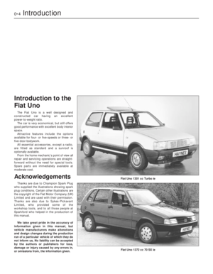 4
4 5
5 6
6 7
7 8
8 9
9 10
10 11
11 12
12 13
13 14
14 15
15 16
16 17
17 18
18 19
19 20
20 21
21 22
22 23
23 24
24 25
25 26
26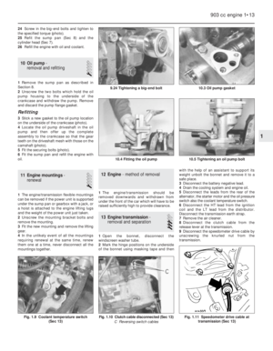 27
27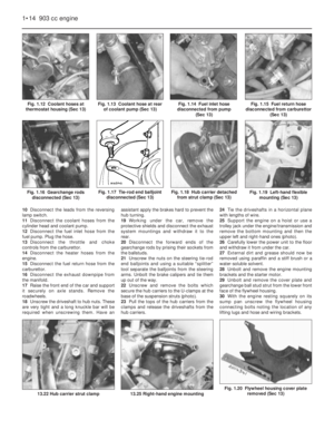 28
28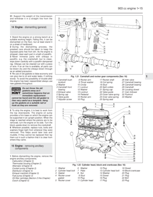 29
29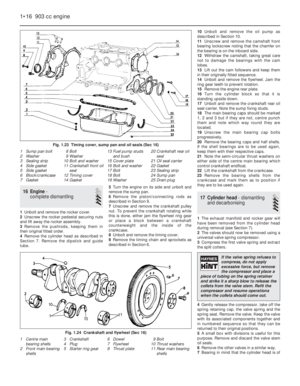 30
30 31
31 32
32 33
33 34
34 35
35 36
36 37
37 38
38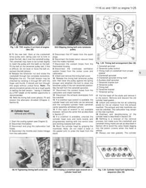 39
39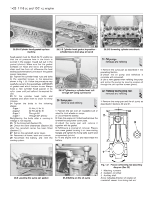 40
40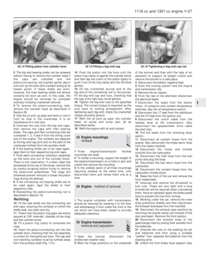 41
41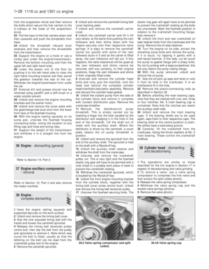 42
42 43
43 44
44 45
45 46
46 47
47 48
48 49
49 50
50 51
51 52
52 53
53 54
54 55
55 56
56 57
57 58
58 59
59 60
60 61
61 62
62 63
63 64
64 65
65 66
66 67
67 68
68 69
69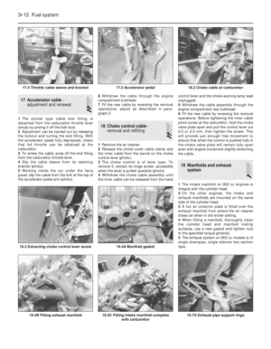 70
70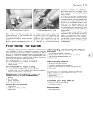 71
71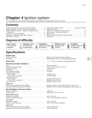 72
72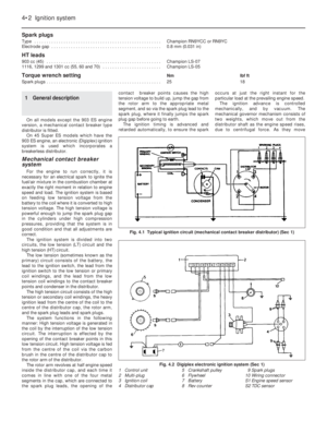 73
73 74
74 75
75 76
76 77
77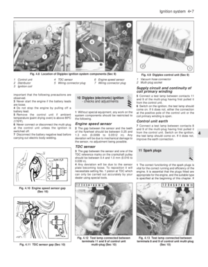 78
78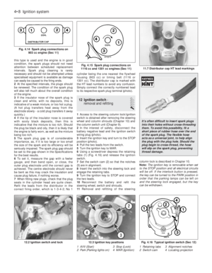 79
79 80
80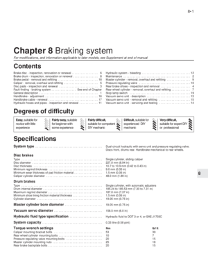 81
81 82
82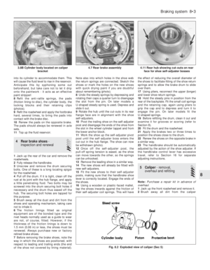 83
83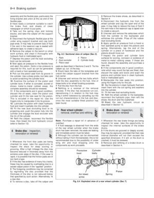 84
84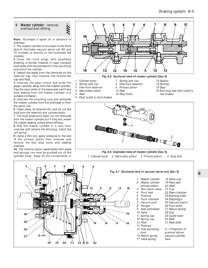 85
85 86
86 87
87 88
88 89
89 90
90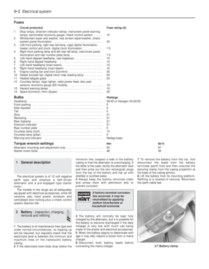 91
91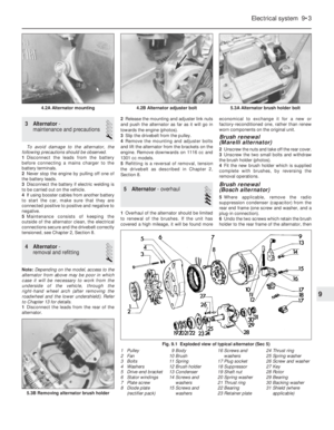 92
92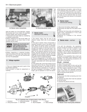 93
93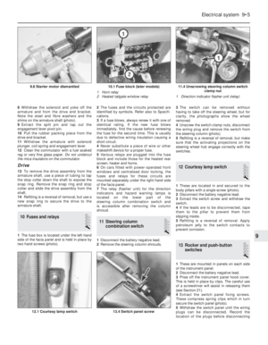 94
94 95
95 96
96 97
97 98
98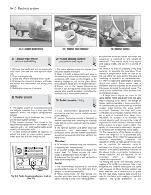 99
99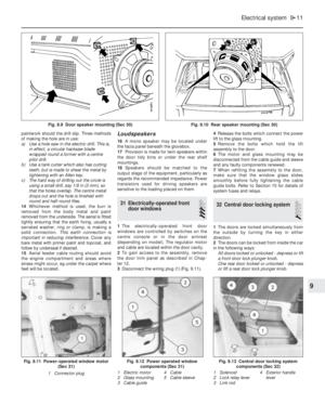 100
100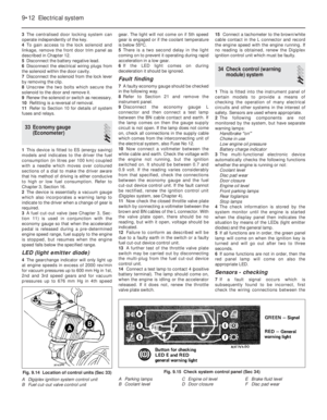 101
101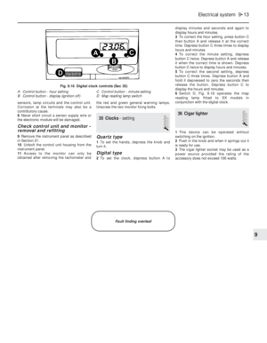 102
102 103
103 104
104 105
105 106
106 107
107 108
108 109
109 110
110 111
111 112
112 113
113 114
114 115
115 116
116 117
117 118
118 119
119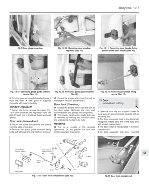 120
120 121
121 122
122 123
123 124
124 125
125 126
126 127
127 128
128 129
129 130
130 131
131 132
132 133
133 134
134 135
135 136
136 137
137 138
138 139
139 140
140 141
141 142
142 143
143 144
144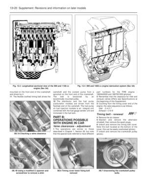 145
145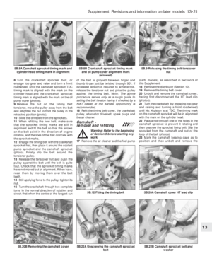 146
146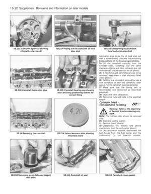 147
147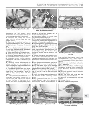 148
148 149
149 150
150 151
151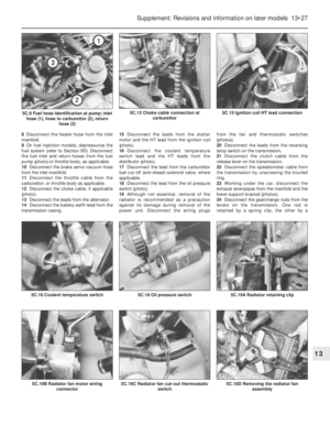 152
152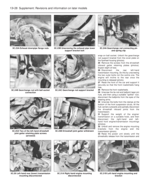 153
153 154
154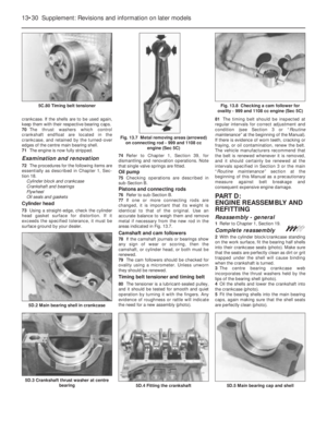 155
155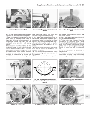 156
156 157
157 158
158 159
159 160
160 161
161 162
162 163
163 164
164 165
165 166
166 167
167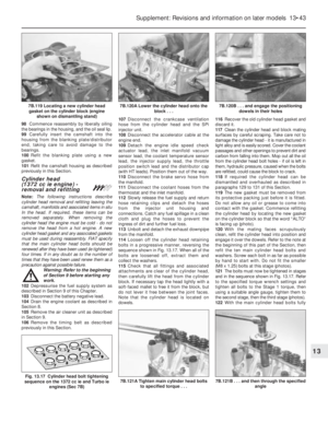 168
168 169
169 170
170 171
171 172
172 173
173 174
174 175
175 176
176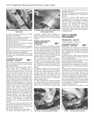 177
177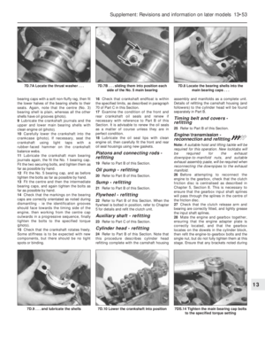 178
178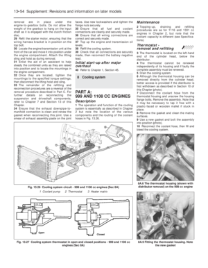 179
179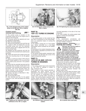 180
180 181
181 182
182 183
183 184
184 185
185 186
186 187
187 188
188 189
189 190
190 191
191 192
192 193
193 194
194 195
195 196
196 197
197 198
198 199
199 200
200 201
201 202
202 203
203 204
204 205
205 206
206 207
207 208
208 209
209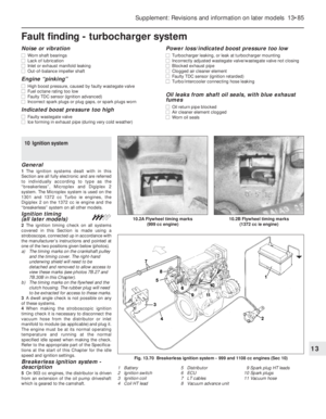 210
210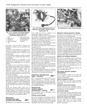 211
211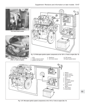 212
212 213
213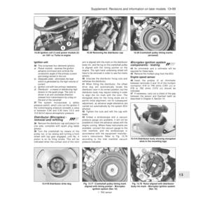 214
214 215
215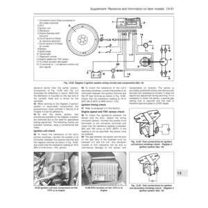 216
216 217
217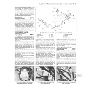 218
218 219
219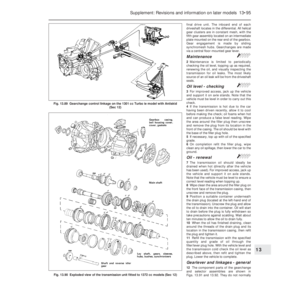 220
220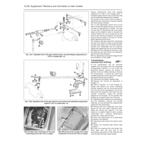 221
221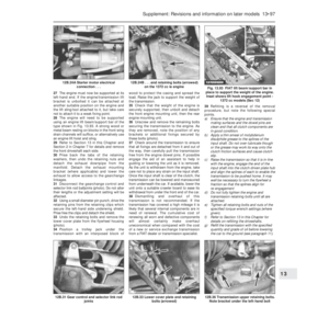 222
222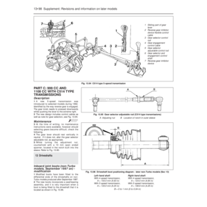 223
223 224
224 225
225 226
226 227
227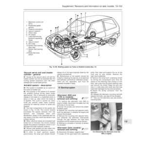 228
228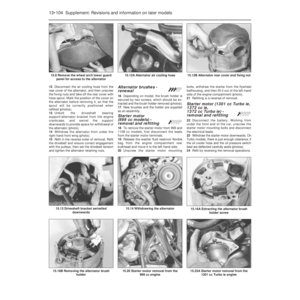 229
229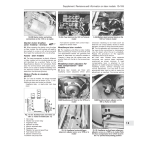 230
230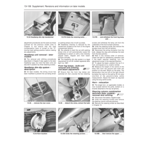 231
231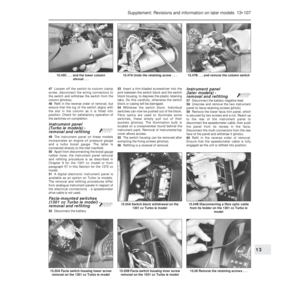 232
232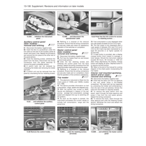 233
233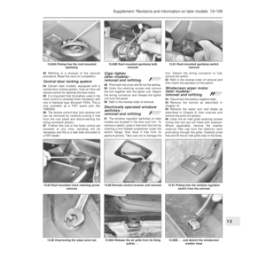 234
234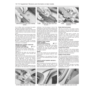 235
235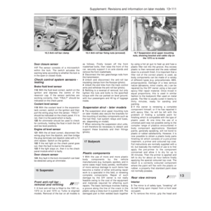 236
236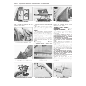 237
237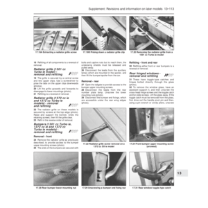 238
238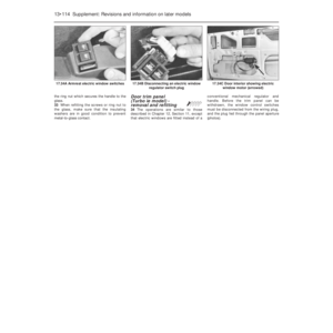 239
239 240
240 241
241 242
242 243
243 244
244 245
245 246
246 247
247 248
248 249
249 250
250 251
251 252
252 253
253 254
254 255
255 256
256 257
257 258
258 259
259 260
260 261
261 262
262 263
263 264
264 265
265 266
266 267
267 268
268 269
269 270
270 271
271 272
272 273
273 274
274 275
275 276
276 277
277 278
278 279
279 280
280 281
281 282
282 283
283 284
284 285
285 286
286 287
287 288
288 289
289 290
290 291
291 292
292 293
293 294
294 295
295 296
296 297
297 298
298 299
299 300
300 301
301 302
302