Page 25 of 303

19Never smear grease on the gasket as,
when the engine heats up, the grease will melt
and may allow compression leaks to develop.
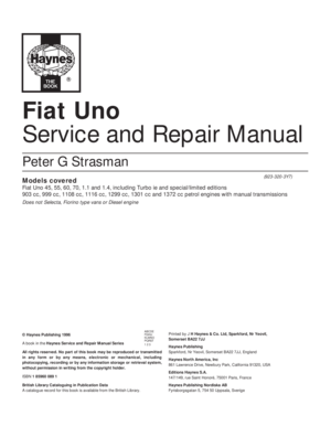
20The cylinder head gasket cannot be fitted
incorrectly due to its asymmetrical shape, but
the word ALTO should be uppermost in any
event (photo).
21The locating dowels should be refitted to
the front right and left-hand side cylinder head
securing bolt holes.
22Carefully fit the cylinder head gasket to
the top of the cylinder block.
23Lower the cylinder head onto the gasket,
taking care not to move the position of the
gasket.
24Screw in the cylinder head bolts finger
tight, remembering the bolt within the intake
manifold and the metal coolant pipe which is
held by the two cylinder head bolts adjacent to
the coolant temperature sender unit (photos).
25Tighten the cylinder head bolts in two
stages, in the specified sequence to the
torque given in Specifications.
26With the cylinder head in position, fit the
pushrods in the same order in which they
were removed. Ensure that they locate
properly in the stems of the tappets and
lubricate the pushrod ends before fitment
(photo).
27Unscrew the rocker arm adjuster screws
as far as they will go.
28Fit the rocker gear over the four studs in
the cylinder head and lower onto the cylinder
head. Make sure the ball ends of the rockers
locate in the cups of the pushrods.29Fit the four nuts and washers to the rocker
shaft pedestal studs and tighten in a
progressive manner to the torque wrench
setting given in the Specifications.
30Adjust the valve clearances as described
in Section 5.
31Fit the exhaust manifold, thermostat
housing and alternator, also the rocker cover
(photo).
32Fit the carburettor, air cleaner and
distributor (Chapter 4).
33Reconnect all hoses and electrical leads,
including the battery.
34Refill the cooling system.
8 Sump pan-
removal and refitting
1
1Drain the engine oil.
2Unscrew and remove the four nuts and
twelve bolts and lift away the sump pan. If it
has stuck on the gasket carefully tap the side
of the mating flange to break the seal.
Remove the gasket and clean away any
pieces of gasket cement which are adhering
to the flanges.
3Remove the sealing strips from the
recesses at either end of the sump pan.
Refitting
4Fit the new sealing strips and if necessary,
trim their ends until they are just proud of the
sump pan flange (photo).5Using thick grease, stick the gasket side
strips to the crankcase.
6Apply a blob of jointing compound at the
points of overlap of the side gaskets and
strips.
7Offer up the sump pan, screw in and tighten
the bolts and nuts progressively (photos).
8Refill the engine with oil.
903 cc engine 1•11
7.24B Cylinder head bolts holding coolant
pipe7.24A Cylinder head bolt in intake manifold7.20 Cylinder head gasket
7.31 Fitting the rocker cover
7.26 Fitting a pushrod
Fig. 1.7 Cylinder head bolt tightening
sequence (Sec 7)1
8.4 Sump pan sealing strip8.7A Fitting the sump pan
Page 26 of 303

9 Pistons/connecting rods-
removal and refitting
3
1Remove the cylinder head as described in
Section 7.
2Remove the sump pan as described in
Section 8.
3Undo and remove the big-end cap retaining
bolts and keep them in their respective order
for correct refitting.
4Check that the connecting rod and big-end
bearing cap assemblies are correctly marked.
Normally the numbers 1-4 are stamped on
adjacent sides of the big-end caps and
connecting rods, indicating which cap fits on
which rod and which way round the cap fits.
The numbers are located on the sides of the
rod and cap furthest away from the camshaft.
5If numbers are not evident, then use a sharp
file to make mating marks across the rod/cap
joint. One line for connecting rod No. 1, two
for connecting rod No. 2 and so on. This will
ensure that there is no confusion later as it is
most important that the caps go back in the
correct position on the connecting rods from
which they were removed. No. 1 piston should
be at the crankshaft pulley end of the engine.
6If the big-end caps are difficult to remove
they may be gently tapped with a soft-faced
hammer.
7To remove the shell bearings, press the
bearing opposite the groove in both the
connecting rod and the connecting rod caps
and the bearings will slide out easily.
8Keep the shells with their original cap or rod
if the bearings are not being renewed.
9Withdraw the pistons and connecting rods
upwards and ensure that they are kept in the
correct order for replacement in the same
bore.
10If the cylinder has a wear ridge at its upper
end then this may make it difficult to remove
the piston. In this event, relieve the sharp
edge of the ridge by scraping.
11Dismantling the pistons is described in
Section 18, paragraph 17.
12Lay the piston and connecting rod
assemblies in the correct order ready for
refitting into their respective bores.13With a wad of clean non-fluffy rag wipe
the cylinder bores clean.
14Position the piston rings so that their gaps
are 120º apart and then lubricate the rings.
15Wipe clean the connecting rod half of the
big-end bearing and the underside of the shell
bearing. Fit the shell bearing in position with
its locating tongue engaged with the
corresponding groove in the connecting rod.
16Fit a piston ring compressor to the top of
the piston, making sure it is tight enough to
compress the piston rings.
17Using a piece of fine wire double check
that the little jet hole in the connecting rod is
clean.
18The pistons, complete with connecting
rods, are fitted to their bores from above. The
number stamped on the connecting rod must
face away from the camshaft with the arrow
on the piston crown pointing towards the
timing cover.19With the base of the piston ring compressor
resting on the cylinder block, apply the wooden
handle of a hammer to the piston crown, strike
the hammer head with the hand and drive the
piston/rod into its bore (photo).
20Draw the rod, complete with shell bearing
down onto its crankpin.
21Generously lubricate the crankpin journals
with engine oil, and turn the crankshaft so that
the crankpin is in the most advantageous
position for the connecting rod to be drawn
into it.
22Wipe clean the connecting rod bearing
cap and back of the shell bearing and fit the
shell bearing in position ensuring that the
locating tongue at the back of the bearing
engages with the locating groove in the
connecting rod cap.
23Generously lubricate the shell bearing and
offer up the connecting rod bearing cap to the
connecting rod (photo).
1•12 903 cc engine
9.23 Big-end cap9.19 Fitting a piston/connecting rod
Fig. 1.8 Piston/connecting rod components (Sec 9)
1 Bolt
2 Connecting rod
3 Oil control ring4 Compression ring
(stepped at base)
5 Compression ring
(marked TOP)6 Gudgeon pin
7 Piston gudgeon pins
8 Big-end shell bearings
8.7B Sump pan nut, bolts and washers
Page 27 of 303
.
25Refit the sump pan (Sec 8) and the
cylinder head (Sec 7).
26Refill the engine with oil and coolant.
10 Oil pump-
removal an")
24Screw in the big-end bolts and tighten to
the specified torque (photo).
25Refit the sump pan (Sec 8) and the
cylinder head (Sec 7).
26Refill the engine with oil and coolant.
10 Oil pump-
removal and refitting
1
1Remove the sump pan as described in
Section 8.
2Unscrew the two bolts which hold the oil
pump housing to the underside of the
crankcase and withdraw the pump. Remove
and discard the pump flange gasket.
Refitting
3Stick a new gasket to the oil pump location
on the underside of the crankcase (photo).
4Locate the oil pump driveshaft in the oil
pump and then offer up the complete
assembly to the crankcase so that the gear
teeth on the driveshaft mesh with those on the
camshaft (photo).
5Fit the securing bolts (photo).
6Fit the sump pan and refill the engine with
oil.
11 Engine mountings-
renewal
1
1The engine/transmission flexible mountings
can be removed if the power unit is supported
under the sump pan or gearbox with a jack, or
a hoist is attached to the engine lifting lugs
and the weight of the power unit just taken.
2Unscrew the mounting bracket bolts and
remove the mounting.
3Fit the new mounting and remove the lifting
gear.
4In the unlikely event of all the mountings
requiring renewal at the same time, renew
them one at a time, never disconnect all the
mountings together.
12 Engine- method of removal
1The engine/transmission should be
removed downwards and withdrawn from
under the front of the car which will have to be
raised sufficiently high to provide clearance.
13 Engine/transmission-
removal and separation
3
1Open the bonnet, disconnect the
windscreen washer tube.
2Mark the hinge positions on the underside
of the bonnet using masking tape and thenwith the help of an assistant to support its
weight unbolt the bonnet and remove it to a
safe place.
3Disconnect the battery negative lead.
4Drain the cooling system and engine oil.
5Disconnect the leads from the rear of the
alternator, the starter motor and the oil pressure
switch also the coolant temperature switch.
6Disconnect the HT lead from the ignition
coil and the LT lead from the distributor.
Disconnect the transmission earth strap.
7Remove the air cleaner.
8Disconnect the clutch cable from the
release lever at the transmission.
9Disconnect the speedometer drive cable by
unscrewing the knurled nut from the
transmission.
903 cc engine 1•13
10.3 Oil pump gasket
10.4 Fitting the oil pump10.5 Tightening an oil pump bolt
9.24 Tightening a big-end bolt
Fig. 1.11 Speedometer drive cable at
transmission (Sec 13)Fig. 1.10 Clutch cable disconnected (Sec 13)
C Reversing switch cablesFig. 1.9 Coolant temperature switch
(Sec 13)
1
Page 28 of 303

Fig. 1.19 Left-hand flexible
mounting (Sec 13)
10Disconnect the leads from the reversing
lamp switch.
11Disconnect the coolant hoses from the")
Fig. 1.20 Flywheel housing cover plate
removed (Sec 13)
Fig. 1.19 Left-hand flexible
mounting (Sec 13)
10Disconnect the leads from the reversing
lamp switch.
11Disconnect the coolant hoses from the
cylinder head and coolant pump.
12Disconnect the fuel inlet hose from the
fuel pump. Plug the hose.
13Disconnect the throttle and choke
controls from the carburettor.
14Disconnect the heater hoses from the
engine.
15Disconnect the fuel return hose from the
carburettor.
16Disconnect the exhaust downpipe from
the manifold.
17Raise the front end of the car and support
it securely on axle stands. Remove the
roadwheels.
18Unscrew the driveshaft to hub nuts. These
are very tight and a long knuckle bar will be
required when unscrewing them. Have anassistant apply the brakes hard to prevent the
hub turning.
19Working under the car, remove the
protective shields and disconnect the exhaust
system mountings and withdraw it to the
rear.
20Disconnect the forward ends of the
gearchange rods by prising their sockets from
the ballstuds.
21Unscrew the nuts on the steering tie-rod
end balljoints and using a suitable “splitter”
tool separate the balljoints from the steering
arms. Unbolt the brake calipers and tie them
up out of the way.
22Unscrew and remove the bolts which
secure the hub carriers to the U-clamps at the
base of the suspension struts (photo).
23Pull the tops of the hub carriers from the
clamps and release the driveshafts from the
hub carriers.24Tie the driveshafts in a horizontal plane
with lengths of wire.
25Support the engine on a hoist or use a
trolley jack under the engine/transmission and
remove the bottom mounting and then the
upper left and right-hand ones (photo).
26Carefully lower the power unit to the floor
and withdraw it from under the car.
27External dirt and grease should now be
removed using paraffin and a stiff brush or a
water-soluble solvent.
28Unbolt and remove the engine mounting
brackets and the starter motor.
29Unbolt and remove the cover plate and
gearchange ball stud strut from the lower front
face of the flywheel housing.
30With the engine resting squarely on its
sump pan unscrew the flywheel housing
connecting bolts noting the location of any
lifting lugs and hose and wiring brackets.
1•14 903 cc engine
13.25 Right-hand engine mounting
Fig. 1.18 Hub carrier detached
from strut clamp (Sec 13)
13.22 Hub carrier strut clamp
Fig. 1.17 Tie-rod end balljoint
disconnected (Sec 13)Fig. 1.16 Gearchange rods
disconnected (Sec 13)
Fig. 1.15 Fuel return hose
disconnected from carburettor
(Sec 13)Fig. 1.14 Fuel inlet hose
disconnected from pump
(Sec 13)Fig. 1.13 Coolant hose at rear
of coolant pump (Sec 13)Fig. 1.12 Coolant hoses at
thermostat housing (Sec 13)
Page 29 of 303

1Stand the engine on a strong bench at a
suitable working height. Failing")
31Support the weight of the transmission
and withdraw it in a straight line from the
engine.
14 Engine- dismantling (general)
1Stand the engine on a strong bench at a
suitable working height. Failing this, it can be
dismantled on the floor, but at least stand it
on a sheet of hardboard.
2During the dismantling process, the
greatest care should be taken to keep the
exposed parts free from dirt. As the engine is
stripped, clean each part in a bath of paraffin.
3Never immerse parts with oilways in
paraffin, e.g. the crankshaft, but to clean,
wipe down carefully with a paraffin dampened
rag. Oilways can be cleaned out with a piece
of wire. If an air line is available, all parts can
be blown dry and the oilways blown through
as an added precaution.
4Re-use of old gaskets is false economy and
can give rise to oil and water leaks, if nothing
worse. To avoid the possibility of trouble after
the engine has been reassembled always use
new gaskets throughout.
5To strip the engine, it is best to work from
the top downwards. The engine oil sump
provides a firm base on which the engine can
be supported in an upright position. When the
stage is reached where the pistons are to be
removed, turn the engine on its side. Turn the
block upside down to remove the crankshaft.
6Wherever possible, replace nuts, bolts and
washers finger-tight from wherever they were
removed. This helps avoid later loss and
muddle. If they cannot be replaced then lay
them out in such a fashion that it is clear from
where they came.
15 Engine- removing ancillary
components
1Before dismantling the engine, remove the
engine ancillary components.
Carburettor (Chapter 3)
Thermostat housing (Chapter 2)
Alternator (Chapter 9)
Coolant pump (Chapter 2)
Distributor (Chapter 4)
Exhaust manifold (Chapter 3)
Fuel pump (Chapter 3)
Oil filter cartridge (Section 2 this Chapter)
Clutch (Chapter 5)
903 cc engine 1•15
Fig. 1.21 Camshaft and rocker gear components (Sec 16)
Fig. 1.22 Cylinder head, block and crankcase (Sec 16)
1 Camshaft bush
lockbolt
2 Washer
3 Camshaft front
bearing
4 Exhaust valve
5 Spring cap
6 Valve guide
7 Adjuster screw8 Rocker arm
9 Thrust washer
10 Circlip
11 Locknut
12 Washer
13 Locknut
14 Pedestal
15 Rocker arm
16 Plug17 Rocker shaft
18 Coil spring
19 Stud
20 Split collets
21 Spring cap
22 Valve guide
23 Outer valve spring
24 Inner valve spring
25 Spring seat26 Inlet valve
27 Camshaft bearing
28 Camshaft bearing
29 Camshaft
30 Locating dowel
31 Cam follower
32 Pushrod
33 Washer
1 Washer
2 Cylinder head bolt
3 Gasket
4 Rocker cover
gasket
5 Rocker cover6 Washer
7 Plate
8 Nut
9 Stud
10 Plug
11 Cylinder head12 Plug
13 Cylinder head bolt
14 Washer
15 Dowel
16 Plug
17 Plug18 Dowel
19 Block/crankcase
20 Plug
21 Plug
22 Bolt
23 Plug
1
Do not throw the old
gaskets away as it
sometimes happens that an
immediate replacement
cannot be found and the old gasket is
then very useful as a template. Hang
up the gaskets on a suitable nail or
hook as they are removed.
Page 30 of 303

16 Engine-
complete dismantling
3
1Unbolt and remove the rocker cover.
2Unscrew the rocker pedestal securing nuts
and lift away the rocker assembly.
3Remove the pushrods, keeping them in
their original fitted order.
4Remove the cylinder head as described in
Section 7. Remove the dipstick and guide
tube.5Turn the engine on its side and unbolt and
remove the sump pan.
6Remove the piston/connecting rods as
described in Section 9.
7Unscrew and remove the crankshaft pulley
nut. To prevent the crankshaft rotating while
this is done, either jam the flywheel ring gear
or place a block between a crankshaft
counterweight and the inside of the
crankcase.
8Unbolt and remove the timing cover.
9Remove the timing chain and sprockets as
described in Section 6. 10Unbolt and remove the oil pump as
described in Section 10.
11Unscrew and remove the camshaft front
bearing lockscrew noting that the chamfer on
the bearing is on the inboard side.
12Withdraw the camshaft, taking great care
not to damage the bearings with the cam
lobes.
13Lift out the cam followers and keep them
in their originally fitted sequence.
14Unbolt and remove the flywheel. Jam the
ring gear teeth to prevent rotation.
15Remove the engine rear plate.
16Turn the cylinder block so that it is
standing upside down.
17Unbolt and remove the crankshaft rear oil
seal carrier. Note the sump fixing studs.
18The main bearing caps should be marked
1, 2 and 3 but if they are not, centre punch
them and note which way round they are
located.
19Unscrew the main bearing cap bolts
progressively.
20Remove the bearing caps and half shells.
If the shell bearings are to be used again,
keep them with their respective caps.
21Note the semi-circular thrust washers on
either side of the centre main bearing which
control crankshaft endfloat.
22Lift the crankshaft from the crankcase.
23Remove the bearing shells from the
crankcase and mark them as to position if
they are to be used again.
17 Cylinder head- dismantling
and decarbonising
4
1The exhaust manifold and rocker gear will
have been removed from the cylinder head
during removal (see Section 7).
2The valves should now be removed using a
universal valve spring compressor.
3Compress the first valve spring and extract
the split cotters.
4Gently release the compressor, take off the
spring retaining cap, the valve spring and the
spring seat. Remove the valve. Keep the valve
with its associated components together and
in numbered sequence so that they can be
returned to their original positions.
5A small box with divisions is useful for this
purpose. Remove and discard the valve stem
oil seals.
6Remove the other valves in a similar way.
7Bearing in mind that the cylinder head is of
1•16 903 cc engine
Fig. 1.23 Timing cover, sump pan and oil seals (Sec 16)
Fig. 1.24 Crankshaft and flywheel (Sec 16)
1 Sump pan bolt
2 Washer
3 Sealing strip
4 Side gasket
5 Side gasket
6 Block/crankcase
7 Gasket8 Bolt
9 Washer
10 Bolt and washer
11 Crankshaft front oil
seal
12 Timing cover
14 Gasket13 Fuel pump studs
and bush
15 Cover plate
16 Bolt and washer
17 Bolt
18 Bolt
19 Washer20 Crankshaft rear oil
seal
21 Oil seal carrier
22 Gasket
23 Sealing strip
24 Sump pan
25 Drain plug
1 Centre main
bearing shells
2 Front main bearing
shells3 Crankshaft
4 Plug
5 Starter ring gear6 Dowel
7 Flywheel
8 Thrust plate9 Bolt
10 Thrust washers
11 Rear main bearing
shells
If the valve spring refuses to
compress, do not apply
excessive force, but remove
the compressor and place a
piece of tubing on the spring retainer
and strike it a sharp blow to release the
collets from the valve stem. Refit the
compressor and resume operations
when the collets should come out.
Page 31 of 303

light alloy construction and is easily damaged
use a blunt scraper or rotary wire brush to
clean all traces of carbon deposits from the
combustion spaces and the ports. The valve
head stems and valve guides should also be
freed from any carbon deposits. Wash the
combustion spaces and ports down with
paraffin and scrape the cylinder head surface
free of any foreign matter with the side of a
steel rule, or a similar article.
8If the engine is installed in the car, clean the
pistons and the top of the cylinder bores. If
the pistons are still in the block, then it is
essential that great care is taken to ensure
that no carbon gets into the cylinder bores as
this could scratch the cylinder walls or cause
damage to the piston and rings. To ensure
this does not happen, first turn the crankshaft
so that two of the pistons are at the top of
their bores. Stuff rag into the other two bores
or seal them off with paper and masking tape.
The waterways should also be covered with
small pieces of masking tape to prevent
particles of carbon entering the cooling
system and damaging the coolant pump.
9With a blunt scraper carefully scrape away
the carbon from the piston crown, taking care
not to scratch the aluminium. Also scrape
away the carbon from the surrounding lip of
the cylinder wall. When all carbon has been
removed, scrape away the grease which will
now be contaminated with carbon particles,
taking care not to press any into the bores. To
assist prevention of carbon build-up the
piston crown can be polished with a metal
polish. Remove the rags or masking tape from
the other two cylinders and turn the
crankshaft so that the two pistons which were
at the bottom are now at the top. Place rag in
the cylinders which have been decarbonised,
and proceed as just described.
10Examine the head of the valves for pitting
and burning, especially the heads of the
exhaust valves. The valve seatings should be
examined at the same time. If the pitting on
the valve and seat is very slight, the markscan be removed by grinding the seats and
valves together with coarse, and then fine,
valve grinding paste.
11Where bad pitting has occurred to the
valve seats it will be necessary to recut them
and fit new valves. This latter job should be
entrusted to the local agent or engineering
works. In practice it is very seldom that the
seats are so badly worn. Normally it is the
valve that is too badly worn for refitting, and
the owner can easily purchase a new set of
valves and match them to the seats by valve
grinding.
12Valve grinding is carried out as follows.
Smear a trace of coarse carborundum paste
on the seat face and apply a suction grinder
tool to the valve head. With a semi-rotary
motion, grind the valve head to its seat, lifting
the valve occasionally to redistribute the
grinding paste. When a dull matt even surface
is produced on both the valve seat and the
valve, wipe off the paste and repeat the
process with fine carborundum paste, lifting
and turning the valve to redistribute the paste
as before. A light spring placed under the
valve head will greatly ease this operation.
When a smooth unbroken ring of light grey
matt finish is produced, on both valve and
valve seat faces, the grinding operation is
complete. Carefully clean away every trace of
grinding compound, take great care to leave
none in the ports or in the valve guides. Clean
the valve seats with a paraffin soaked rag,
then with a clean rag, and finally, if an air line
is available, blow the valves, valve guides and
valve ports clean.
13Check that all valve springs are intact. If
any one is broken, all should be renewed.
Check the free height of the springs against
new ones. If some springs are not within
specifications, replace them all. Springs suffer
from fatigue and it is a good idea to renew
them even if they look serviceable.
14Check that the oil supply holes in the
rocker arms are clear.
15The cylinder head can be checked for
warping either by placing it on a piece of plate
glass or using a straight-edge and feeler
blades. If there is any doubt or if its block face
is corroded, have it re-faced by your dealer or
motor engineering works.
16Test the valves in their guides for side toside rock. If this is any more than almost
imperceptible, new guides must be fitted.
Again this is a job for your dealer as a special
tool is required to ensure the correct
installation depth and the cylinder head must
be warmed to 80ºC (176ºF) before fitting the
guides.
17Commence reassembly by oiling the stem
of the first valve and pushing it into its guide
which should have been fitted with a new oil
seal (photos).
18Fit the spring seat. Fit the valve spring so
that the closer coils are towards the cylinder
head and then fit the spring retaining cap.
19Compress the valve spring and locate the
split cotters in the valve stem cut-out (photo).
20Gently release the compressor, checking
to see that the collets are not displaced.
21Fit the remaining valves in the same way.
22Tap the end of each valve stem with a
plastic or copper-faced hammer to settle the
components.
23The cylinder head is now ready for
refitting as described in Section 7.
18 Examination and renovation
4
1With the engine stripped down and all parts
thoroughly clean, it is now time to examine
everything for wear. The following items
should be checked and where necessary
renewed or renovated as described in the
following Sections.
Cylinder block and crankcase
2Examine the casting carefully for cracks
especially around the bolt holes and between
cylinders.
3The cylinder bores must be checked for
taper, ovality, scoring and scratching. Start by
examining the top of the cylinder bores. If they
are at all worn, a ridge will be felt on the thrust
side. This ridge marks the limit of piston ring
travel. The owner will have a good indication
of bore wear prior to dismantling by the
quantity of oil consumed and the emission of
blue smoke from the exhaust especially when
the engine is cold.
4An internal micrometer or dial gauge can be
903 cc engine 1•17
17.19 Fitting split collets17.17B Inserting a valve into its guide17.17A Valve stem oil seal
1
Press a little grease into the
gap between the cylinder
walls and the two pistons
which are to be worked on.
Page 32 of 303

used to check bore wear and taper against
the Specifications, but this is a pointless
operation if the engine is obviously in need of
reboring due to excessive oil consumption.
5Your engine reconditioner will be able to
re-bore the block for you and supply the
correct oversize pistons to give the correct
running clearance.
6If the engine has reached the limit for
reboring then cylinder liners can be fitted, but
here again this is a job for your engine
reconditioner.
7To rectify minor bore wear it is possible to
fit proprietary oil control rings. A good way to
test the condition of the engine is to have it at
normal operating temperature with the spark
plugs removed. Screw a compression gauge
(available from most motor accessory stores)
into the first plug hole. Hold the accelerator
fully depressed and crank the engine on the
starter motor for several revolutions. Record
the reading. Zero the tester and check the
remaining cylinders in the same way. All four
compression figures should be approximately
equal and within the tolerance given in the
Specifications. If they are all low, suspect
piston ring or cylinder bore wear. If only one
reading is down, suspect a valve not seating.
Crankshaft and bearings
8Examine the crankpin and main journal
surfaces for signs of scoring or scratches.
Check the ovality of the crankpins at different
positions with a micrometer. If more than
0.001 inch (0.025 mm) out of round, the
crankpins will have to be reground. They will
also have to be reground if there are any
scores or scratches present. Also check the
journals in the same fashion.
9Wear in a crankshaft can be detected while
the engine is running. Big-end bearing and
crankpin wear is indicated by distinct metallic
knocking, particularly noticeable when the
engine is pulling from low engine speeds. Low
oil pressure will also occur.
10Main bearing and journal wear is indicated
by engine rumble increasing in severity as the
engine speed increases. Low oil pressure will
again be an associated condition.
11Crankshaft grinding should be carried outby specialist engine reconditioners who will
supply the matching undersize bearing shells
to give the required running clearance.
12Inspect the connecting rod big-end and
main bearing shells for signs of general wear,
scoring, pitting and scratching. The bearings
should be matt grey in colour.
13If a copper colour is evident, then the
bearings are badly worn and the surface
material has worn away to expose the underlay.
Renew the bearings as a complete set.
14At the time of major overhaul it is
worthwhile renewing the bearing shells as a
matter of routine even if they appear to be in
reasonably good condition.
15Bearing shells can be identified by the
marking on the back of the shell. Standard
sized shells are usually marked STD or 0.00.
Undersized shells are marked with the
undersize such as 0.25 mm.
Connecting rods
16Check the alignment of the connecting
rods visually. If you suspect distortion, have
them checked by your dealer or engine
reconditioner on the special jig which he will
have.
17The gudgeon pin is an interference fit in
the connecting rod small-end and removal or
refitting and changing a piston is a job best
left to your dealer or engine reconditioner due
to the need for a press and jig and careful
heating of the connecting rod.
Pistons and piston rings
18If the cylinders have been rebored, then
the reconditioner will supply the oversize
pistons and rings and the gudgeon pins. Give
the job of fitting the new pistons to the
connecting rods to him.
19If the original piston rings or just new rings
are to be fitted to the original pistons, use
great care to remove and fit the rings as they
are easily broken if expanded too much.
Always remove and fit rings from the crown
end.
20If three old feeler blades are slid behind
the piston rings and located at equidistant
points, the rings may be removed or fitted
without their dropping into the wrong grooves
and will reduce the chance of breakage
(photo).
21If the original pistons are being refitted,
make sure that the ring grooves and their oil
return holes are cleaned out and freed from
carbon. A piece of piston ring is a useful tool
for this purpose.
22The three pistons rings are as follows:
Top - Thinner compression marked TOP
Second - Thicker compression, step at base
Bottom - Oil control (photo)
23If proprietary wear control rings are to be
fitted to overcome bore wear, fit them strictly
in accordance with the manufacturer’s
instructions.
24Always check the piston ring groove
1•18 903 cc engine
18.24A Checking piston ring groove
clearance18.22 Piston ring marking
18.20 Using feeler blades to fit piston ringsFig. 1.26 Piston/connecting rod
relationship (Sec 18)Fig. 1.25 Checking a crankpin (Sec 18)
 1
1 2
2 3
3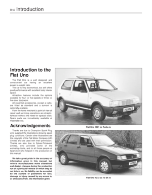 4
4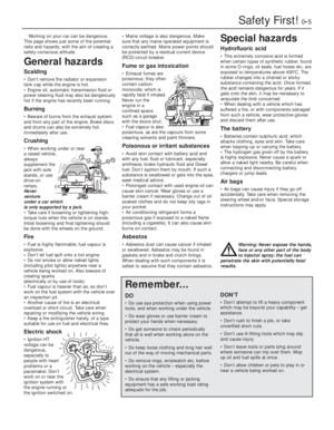 5
5 6
6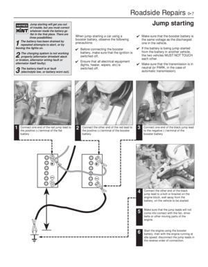 7
7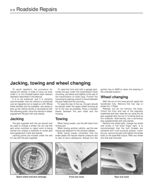 8
8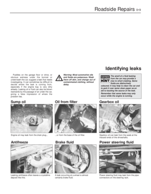 9
9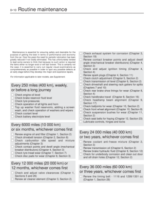 10
10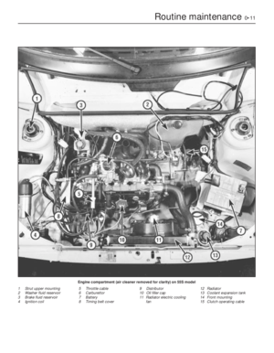 11
11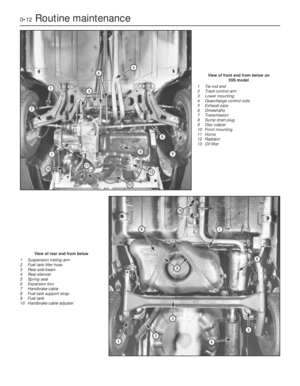 12
12 13
13 14
14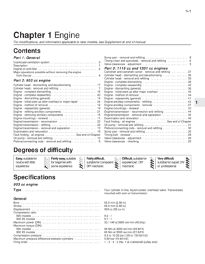 15
15 16
16 17
17 18
18 19
19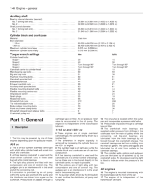 20
20 21
21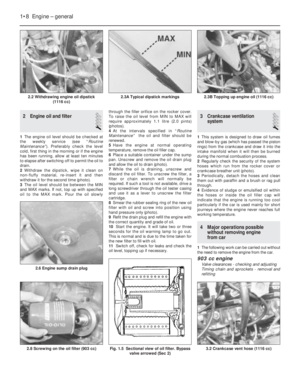 22
22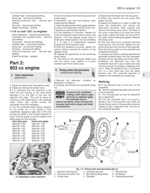 23
23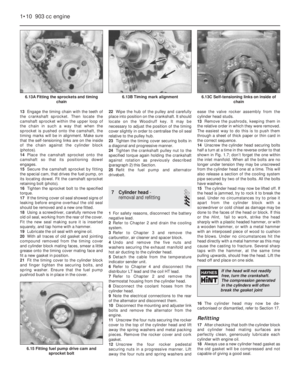 24
24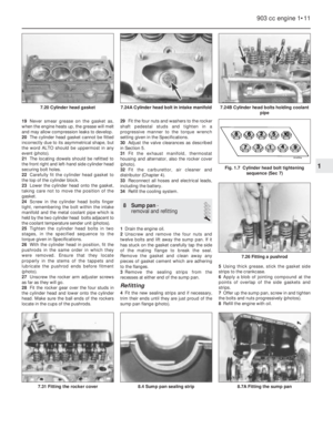 25
25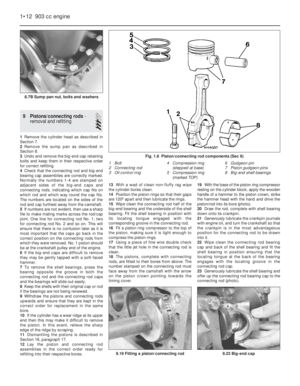 26
26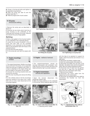 27
27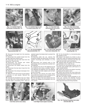 28
28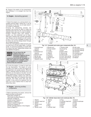 29
29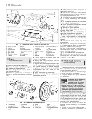 30
30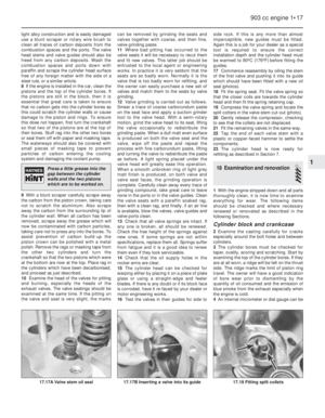 31
31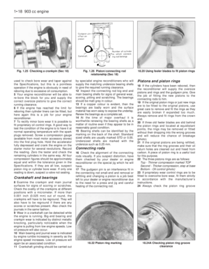 32
32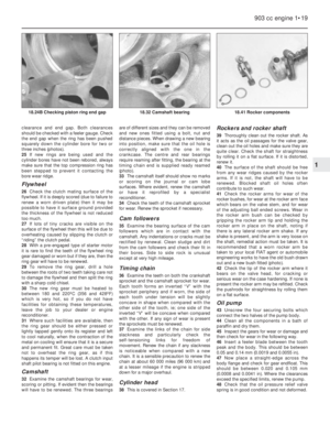 33
33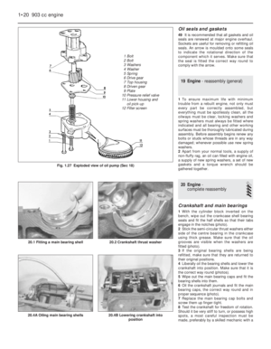 34
34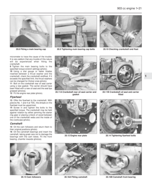 35
35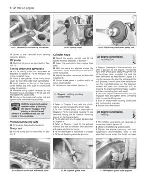 36
36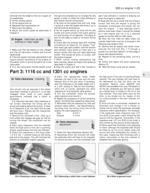 37
37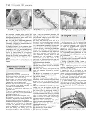 38
38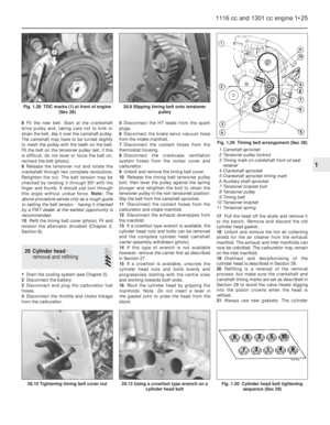 39
39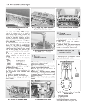 40
40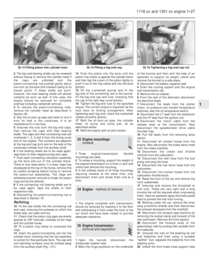 41
41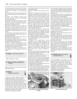 42
42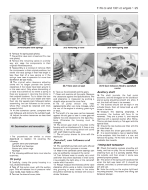 43
43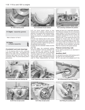 44
44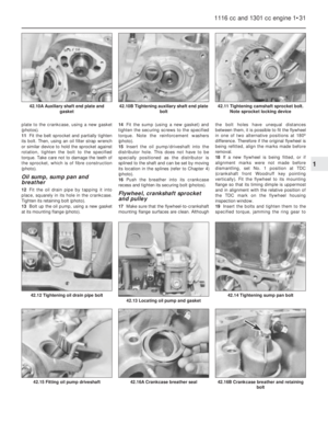 45
45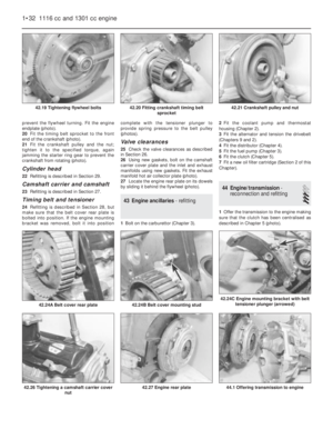 46
46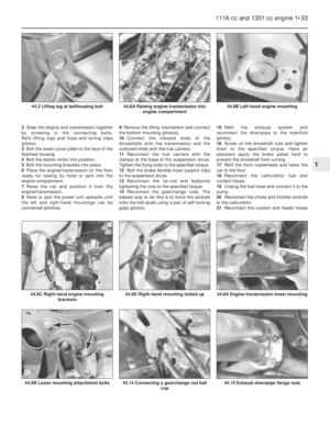 47
47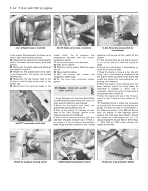 48
48 49
49 50
50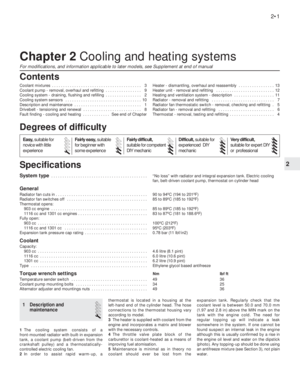 51
51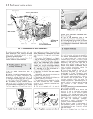 52
52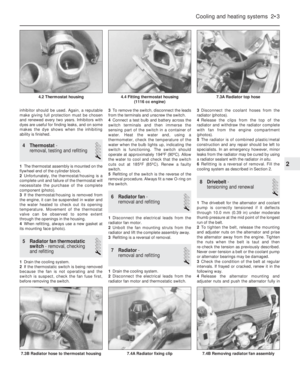 53
53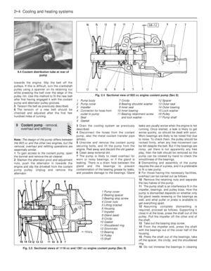 54
54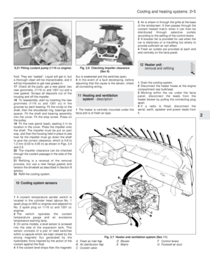 55
55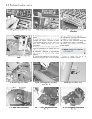 56
56 57
57 58
58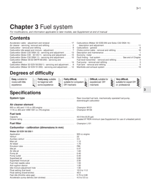 59
59 60
60 61
61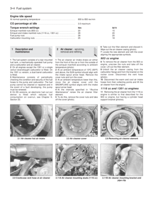 62
62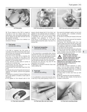 63
63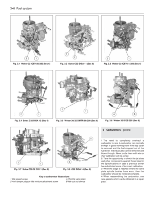 64
64 65
65 66
66 67
67 68
68 69
69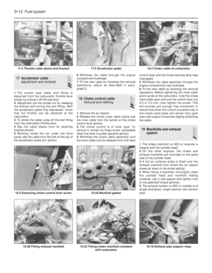 70
70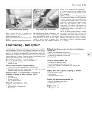 71
71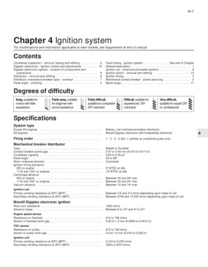 72
72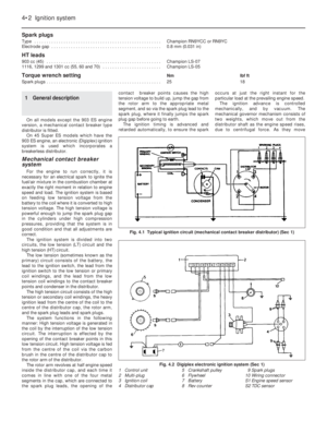 73
73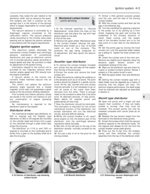 74
74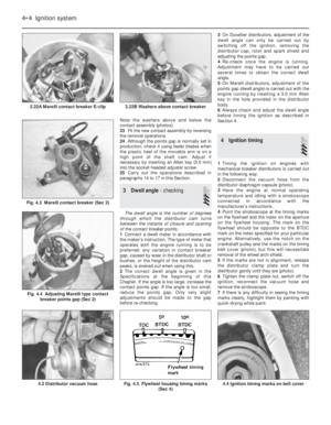 75
75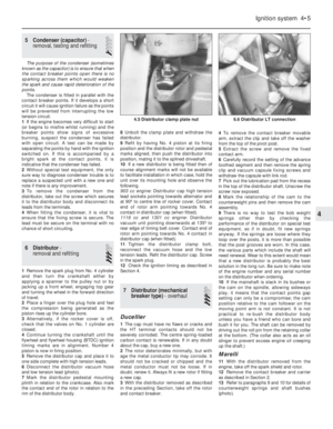 76
76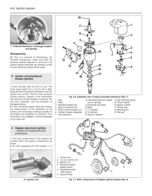 77
77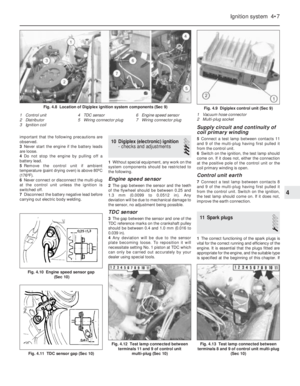 78
78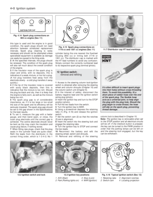 79
79 80
80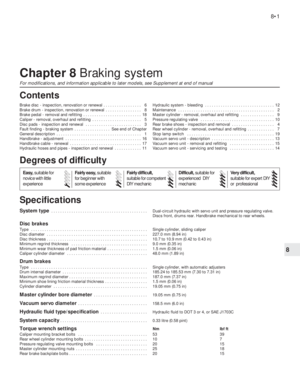 81
81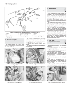 82
82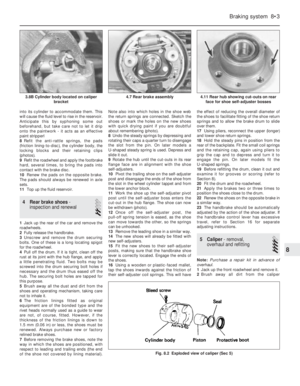 83
83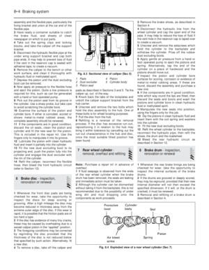 84
84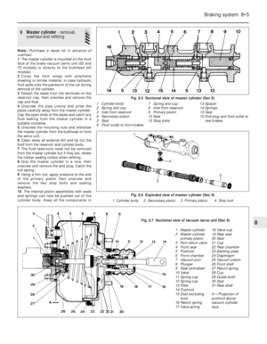 85
85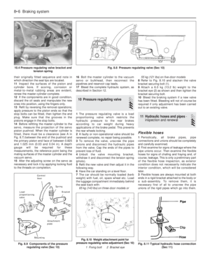 86
86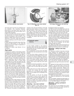 87
87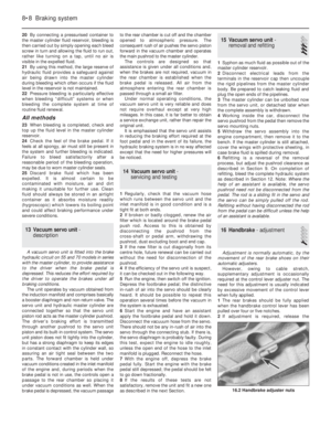 88
88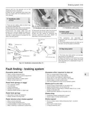 89
89 90
90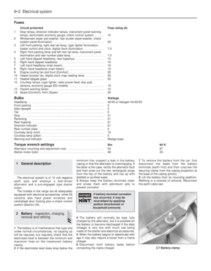 91
91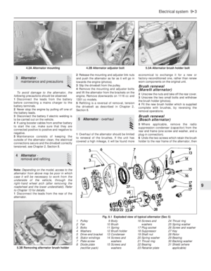 92
92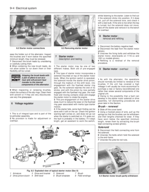 93
93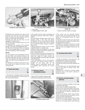 94
94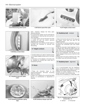 95
95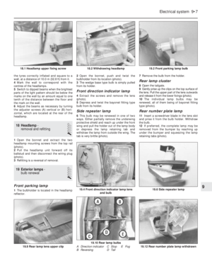 96
96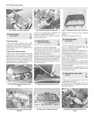 97
97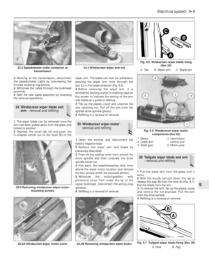 98
98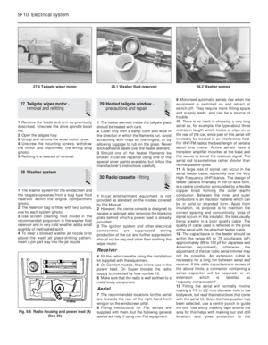 99
99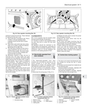 100
100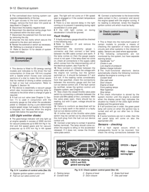 101
101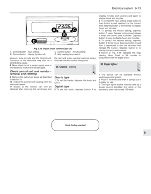 102
102 103
103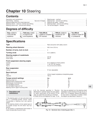 104
104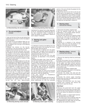 105
105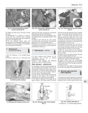 106
106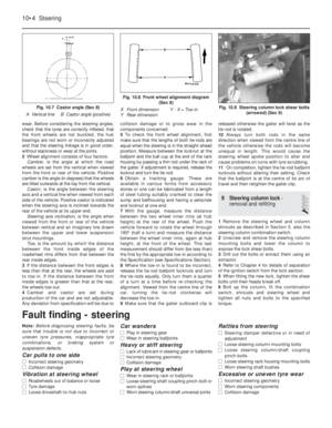 107
107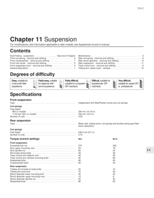 108
108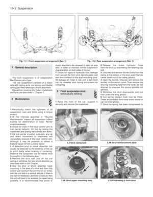 109
109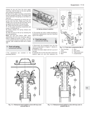 110
110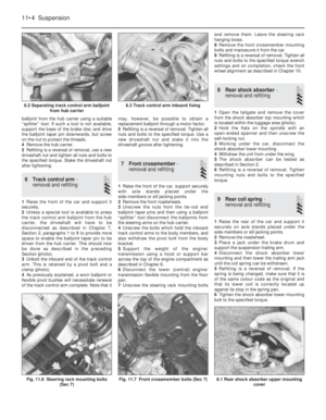 111
111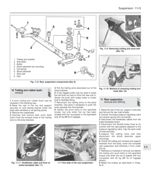 112
112 113
113 114
114 115
115 116
116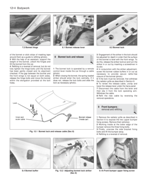 117
117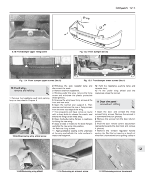 118
118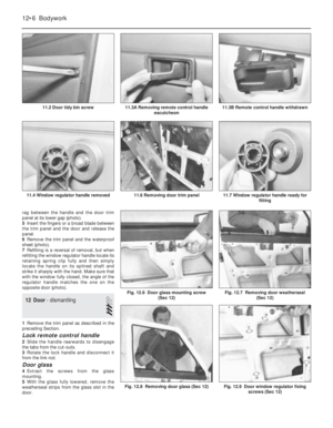 119
119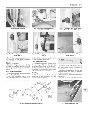 120
120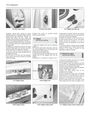 121
121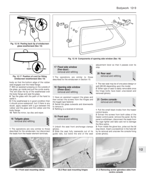 122
122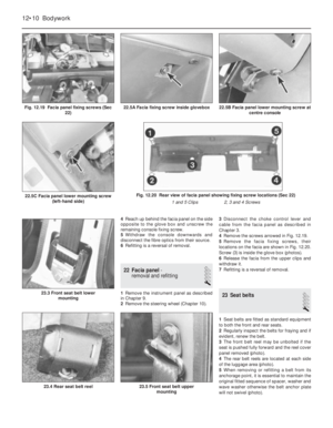 123
123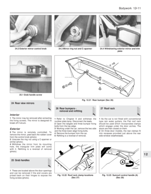 124
124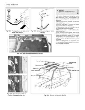 125
125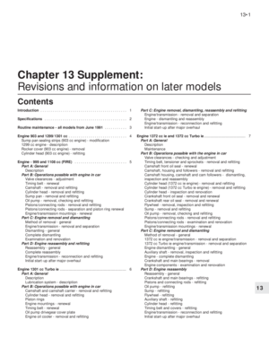 126
126 127
127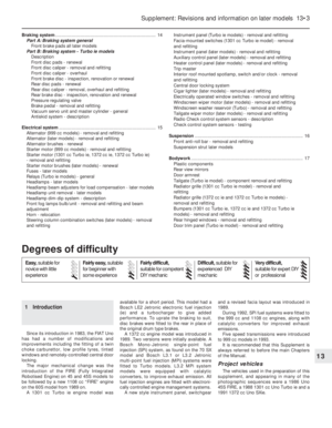 128
128 129
129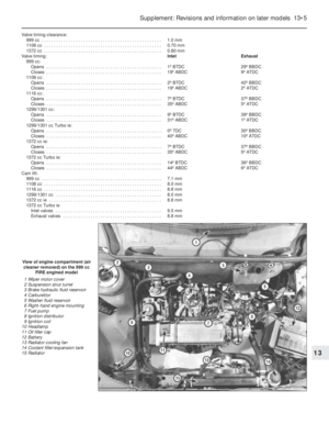 130
130 131
131 132
132 133
133 134
134 135
135 136
136 137
137 138
138 139
139 140
140 141
141 142
142 143
143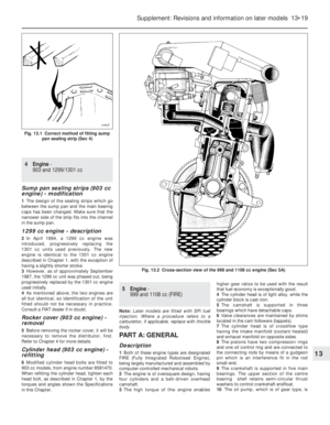 144
144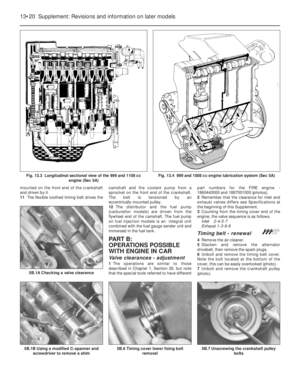 145
145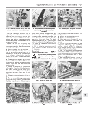 146
146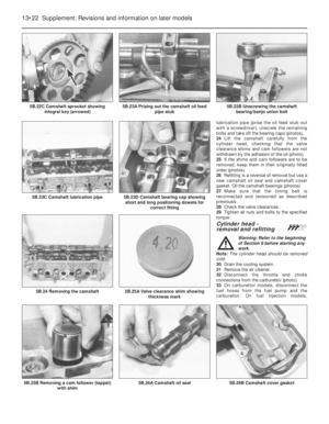 147
147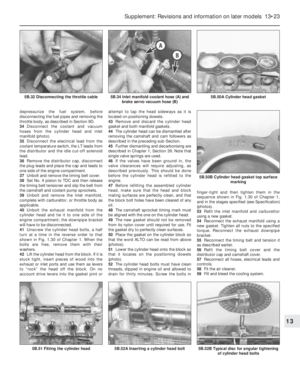 148
148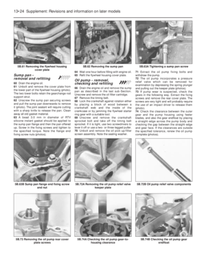 149
149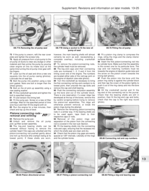 150
150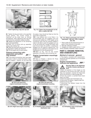 151
151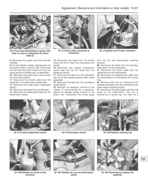 152
152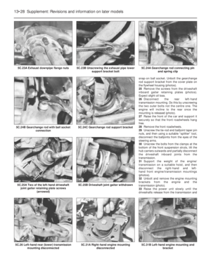 153
153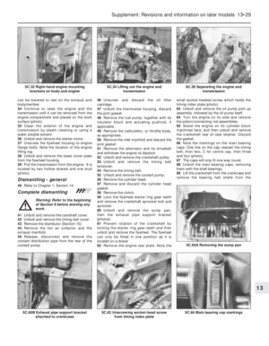 154
154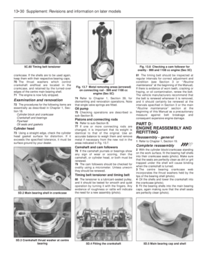 155
155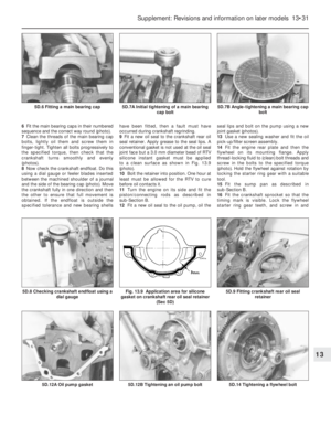 156
156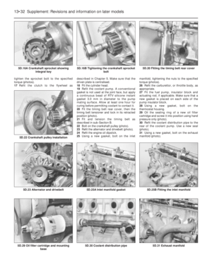 157
157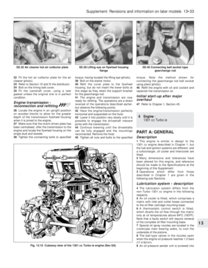 158
158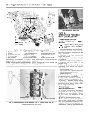 159
159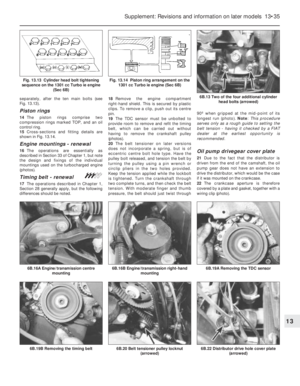 160
160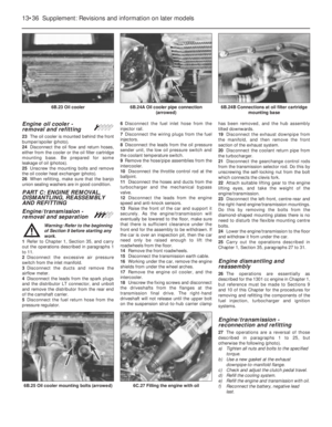 161
161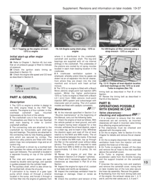 162
162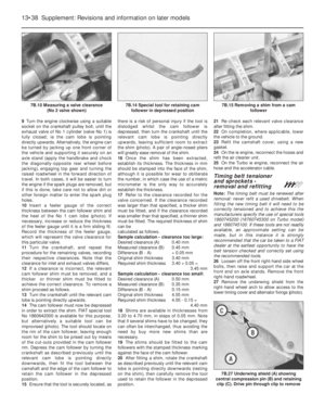 163
163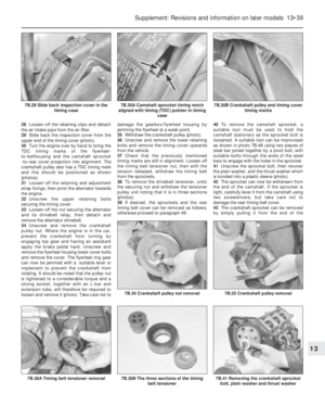 164
164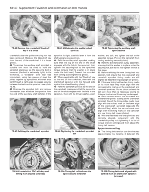 165
165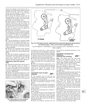 166
166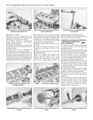 167
167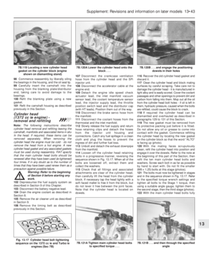 168
168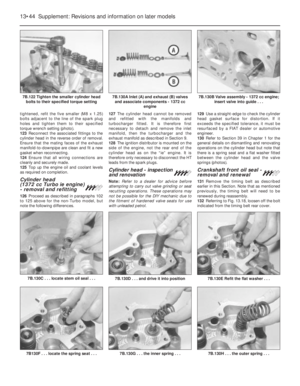 169
169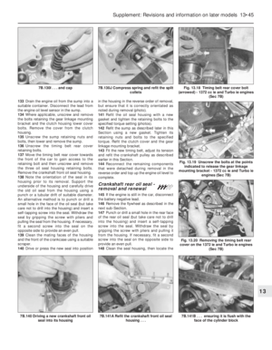 170
170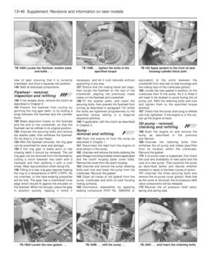 171
171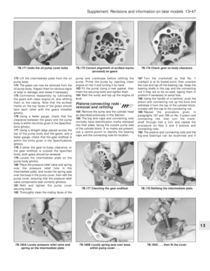 172
172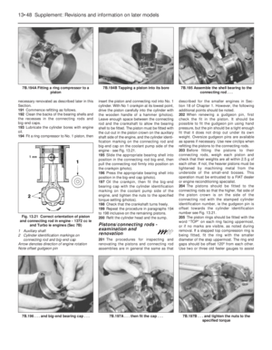 173
173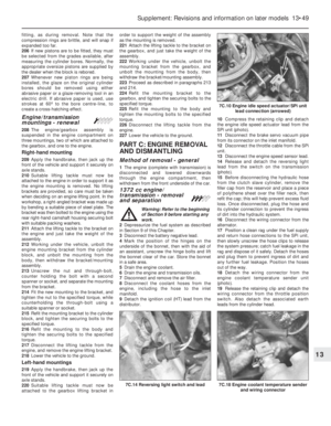 174
174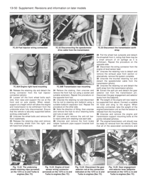 175
175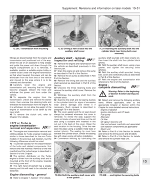 176
176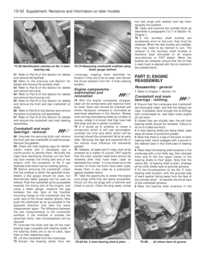 177
177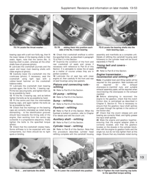 178
178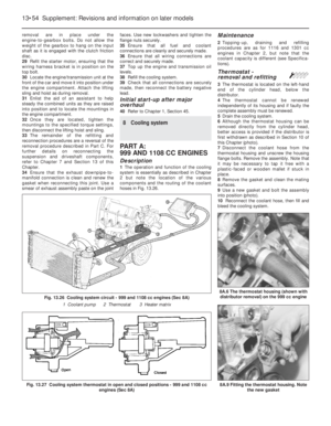 179
179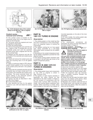 180
180 181
181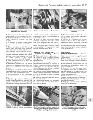 182
182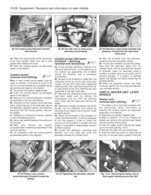 183
183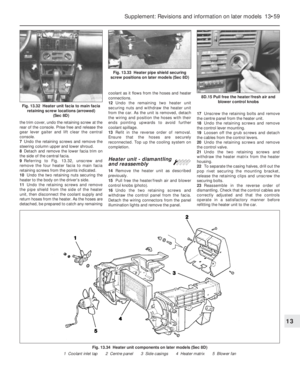 184
184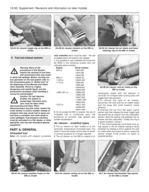 185
185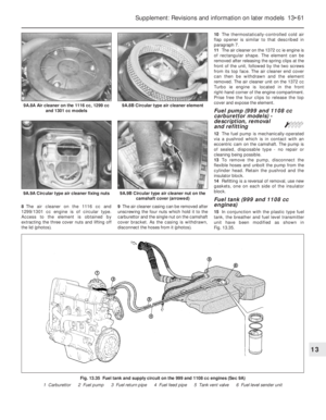 186
186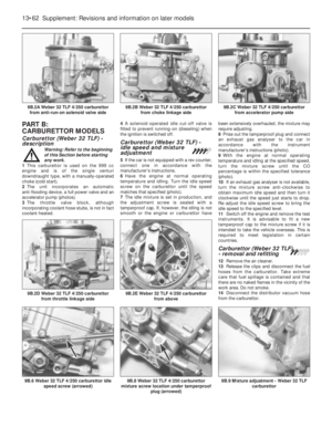 187
187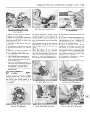 188
188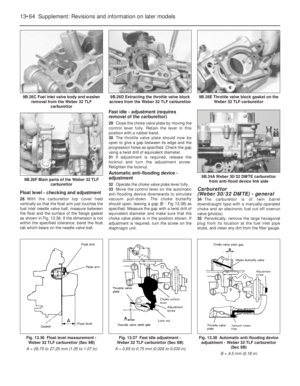 189
189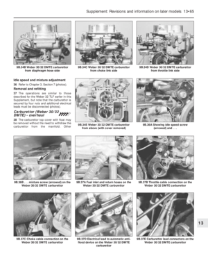 190
190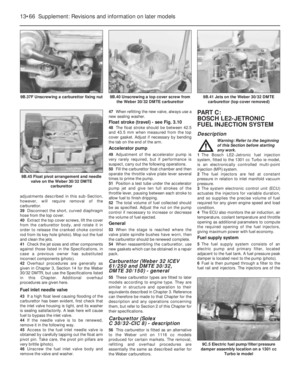 191
191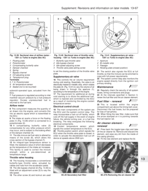 192
192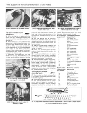 193
193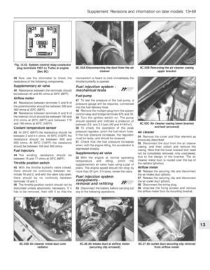 194
194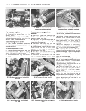 195
195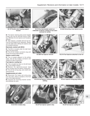 196
196 197
197 198
198 199
199 200
200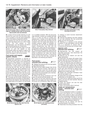 201
201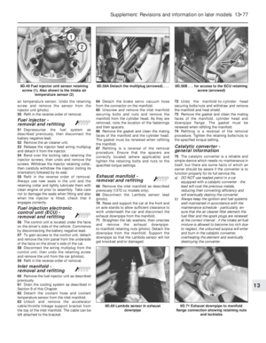 202
202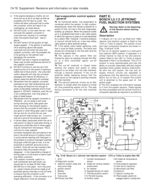 203
203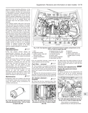 204
204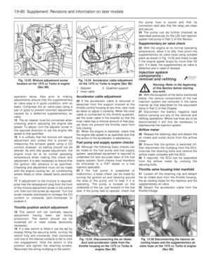 205
205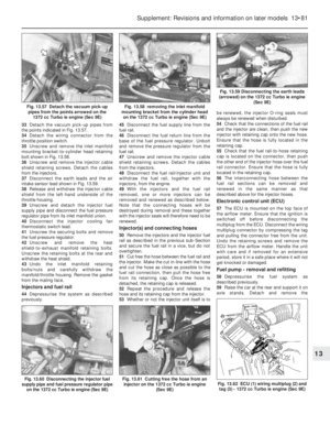 206
206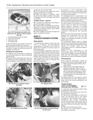 207
207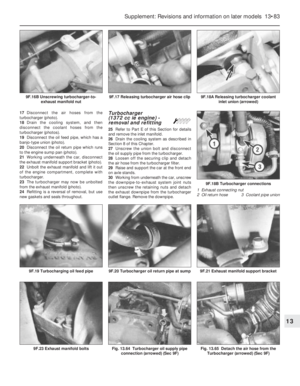 208
208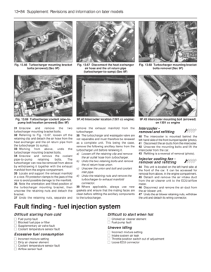 209
209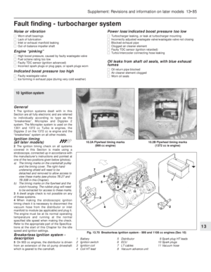 210
210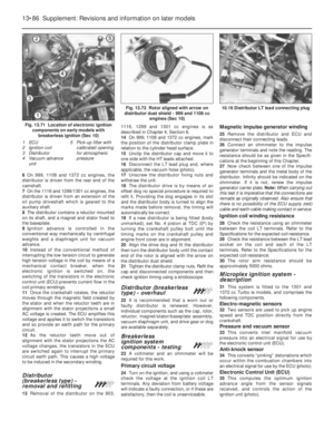 211
211 212
212 213
213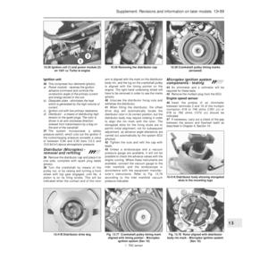 214
214 215
215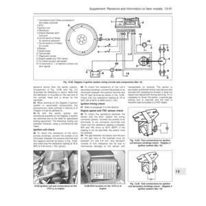 216
216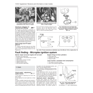 217
217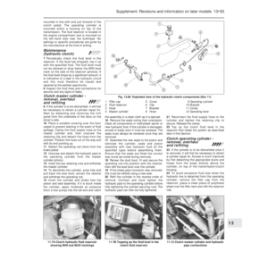 218
218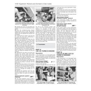 219
219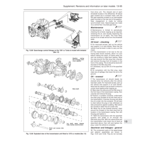 220
220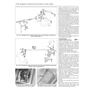 221
221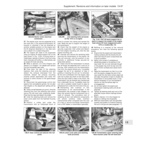 222
222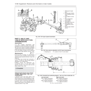 223
223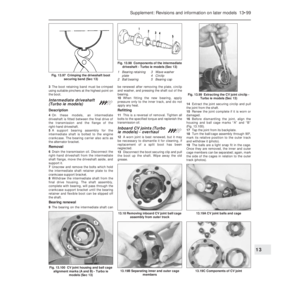 224
224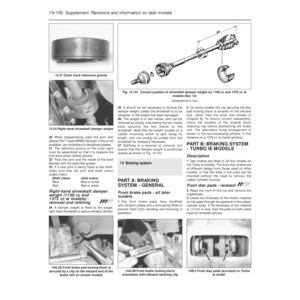 225
225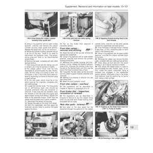 226
226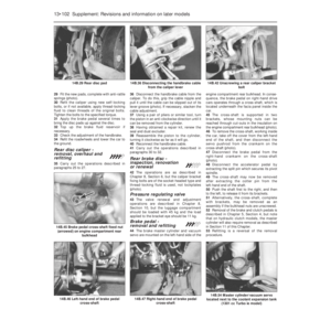 227
227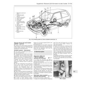 228
228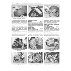 229
229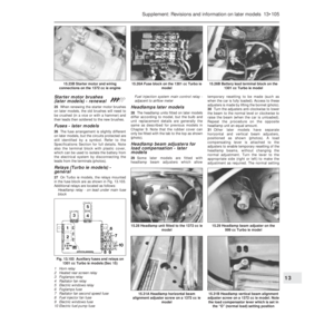 230
230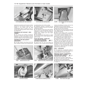 231
231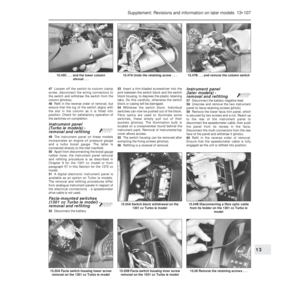 232
232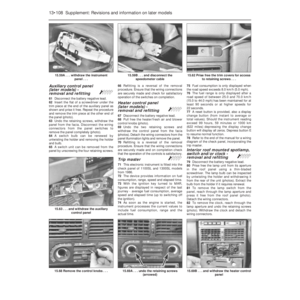 233
233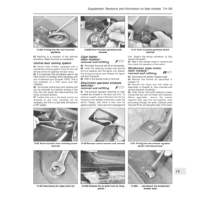 234
234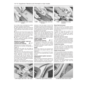 235
235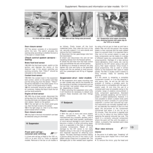 236
236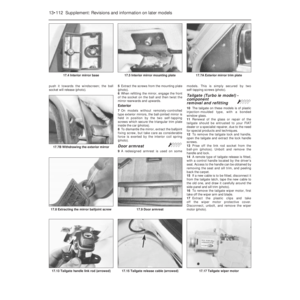 237
237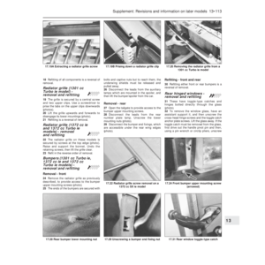 238
238 239
239 240
240 241
241 242
242 243
243 244
244 245
245 246
246 247
247 248
248 249
249 250
250 251
251 252
252 253
253 254
254 255
255 256
256 257
257 258
258 259
259 260
260 261
261 262
262 263
263 264
264 265
265 266
266 267
267 268
268 269
269 270
270 271
271 272
272 273
273 274
274 275
275 276
276 277
277 278
278 279
279 280
280 281
281 282
282 283
283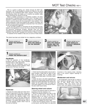 284
284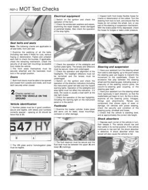 285
285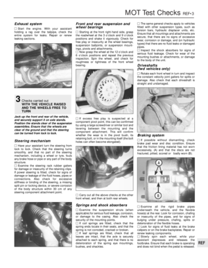 286
286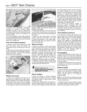 287
287 288
288 289
289 290
290 291
291 292
292 293
293 294
294 295
295 296
296 297
297 298
298 299
299 300
300 301
301 302
302