Page 177 of 303

61Refer to Part B of this Section for details
and remove the flywheel.
62Refer to the previous sub-Section for
details and remove the auxiliary shaft.
63Refer to Part B of this Section for details
and remove the sump.
64Refer to Part B of this Section for details
and remove the oil pump unit.
65Refer to Part B of this Section for details
and remove the front and rear crankshaft oil
seals.
66Refer to Part B of this Section and remove
the piston/connecting rod assemblies.
67Refer to Part B of this Section for details
and remove the crankshaft and main bearing
assemblies.
Crankshaft and main
bearings - removal#
68Unscrew the securing bolts and remove
the front and rear crankshaft oil seal housings.
Recover the gaskets.
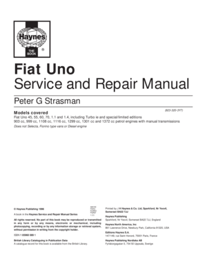
69Check the main bearing caps for identifi-
cation marks and if necessary use a
centre-punch to identify them. Normally the
caps have identifying notches cut into their
top face nearest the timing belt end of the
engine, with the exception of No 5 cap
(flywheel end) which has no marking (photo).
70Before removing the crankshaft, check
that the endfloat is within the specified limits.
Ideally a dial gauge should be used, but
alternatively feeler gauges can be used as
follows. Push the crankshaft as far as possible
towards the timing end of the engine, and
using a feeler gauge, measure the gap
between the rear face of the flywheel
mounting flange on the crankshaft and the
outer face of the thrust washer (photo). Now
push the crankshaft as far as possible in the
opposite direction and take the same
measurement again. The difference between
the two measurements is the crankshaft
endfloat. If the endfloat is outside the
specified limits, new thrustwashers will be
required.
71Unscrew the bolts and tap off the main
bearing caps complete with bearing shells. If
the bearing shells are to be re-used, tape
them to their respective caps.
72Lift the crankshaft from the crankcase.
73Extract the bearing shells from thecrankcase, keeping them identified for
location if they are to be re-used, and recover
the thrust washers from No. 5 main bearing
location.
Engine components -
examination and
renovation
#
74With the engine completely stripped,
clean all the components and examine them
for wear. Each part should be checked and
where necessary renewed or renovated as
described elsewhere in this Section. Renew
main and big-end bearing shells as a matter of
course, unless it is known that they have had
little wear and are in perfect condition.
75If in doubt as to whether to renew a
component which is still just serviceable,
consider the time and effort which will be
incurred should the component fail at an early
date. Obviously the age and expected life of
the vehicle must influence the standards
applied.
76Gaskets, oil seals and O-rings must all be
renewed as a matter of course. FIAT specify
that the main cylinder head bolts should be
renewed after they have been used (ie
tightened) four times - if in any doubt as to the
number of times the bolts have been used,
renew them in any case as a precaution
against possible failure.
77Take the opportunity to renew the engine
core plugs while they are easily accessible.
Knock out the old plugs with a hammer and
chisel or punch. Clean the plug seats, smearthe new plugs with sealant and tap them
squarely into position.
78Clean and examine the cylinder block as
described in paragraphs 2 to 7 of Section 18,
Chapter 1.
79If the auxiliary shaft bushes are
excessively worn or are oval, they must be
renewed. When the new bushes are installed,
they may need to be reamed to suit. The
renewal of the auxiliary shaft bushes is
therefore best entrusted to an engine
reconditioner or FIAT dealer. When the
bushes are renewed, ensure that the oil hole
in each bush is aligned with the oil channel in
the cylinder block.
PART D: ENGINE
REASSEMBLY
Reassembly - general
1Refer to Chapter 1, Section 19.
Crankshaft and main
bearings - refitting#
2Ensure that the crankcase and crankshaft
are thoroughly clean, and that the oilways are
clear. If possible, blow through the oil drillings
with compressed air, and inject clean engine
oil into them.
3Unless they are virtually new, the old main
bearing shells should be renewed. Failure to
do so is a false economy.
4If new bearing shells are being fitted, wipe
away all traces of protective grease.
5Note that there is a tag on the back of each
bearing shell, which engages with a groove in
the relevant seat in the crankcase or bearing
cap.
6Wipe clean the bearing shell locations in the
crankcase with a non-fluffy rag, then lubricate
them and fit the five upper halves of the
bearing shells to their seats. Note that the
centre (No. 3) bearing shell is plain, whereas
all the other shells have oil grooves (photos).
7Fit the thrustwashers to the No. 5 main
bearing shell location, with the grooved side
of each washer facing away from the face of
the cylinder block - ie towards the thrust face
of the crankshaft (photos).
8Wipe the bearing shell locations in the
13•52 Supplement: Revisions and information on later models
7D.6B . . . all others have oil groove7D.6A No. 3 main bearing shell is plain . . .
7C.70 Measuring crankshaft endfloat using
feeler gauge method7C.69 Identification notches on No. 3 main
bearing cap
Page 178 of 303

bearing shell is plain, whereas all the other
shells have o")
bearing caps with a soft non-fluffy rag, then fit
the lower halves of the bearing shells to their
seats. Again, note that the centre (No. 3)
bearing shell is plain, whereas all the other
shells have oil grooves (photo).
9Lubricate the crankshaft journals and the
upper and lower main bearing shells with
clean engine oil (photo).
10Carefully lower the crankshaft into the
crankcase (photo). If necessary, seat the
crankshaft using light taps with a
rubber-faced hammer on the crankshaft
balance webs.
11Lubricate the crankshaft main bearing
journals again, the fit the No. 1 bearing cap.
Fit the two securing bolts, and tighten them as
far as possible by hand.
12Fit the No. 5 bearing cap, and as before
tighten the bolts as far as possible by hand.
13Fit the centre and then the intermediate
bearing caps, and again tighten the bolts as
far as possible by hand.
14Check that the markings on the bearing
caps are correctly orientated as noted during
dismantling - ie the identification grooves
should face towards the timing side of the
engine, then working from the centre cap
outwards in a progressive sequence, finally
tighten the bolts to the specified torque
(photo).
15Check that the crankshaft rotates freely.
Some stiffness is to be expected with new
components, but there should be no tight
spots or binding.16Check that crankshaft endfloat is within
the specified limits, as described in paragraph
70 of Part C in this Section.
17Examine the condition of the front and
rear crankshaft oil seals and renew if
necessary with reference to Part B of this
Section. It is advisable to renew the oil seals
as a matter of course unless they are in
perfect condition.
18Lubricate the oil seal lips with clean
engine oil, then carefully fit the front and rear
oil seal housings using new gaskets.
Pistons and connecting rods -
refitting
19Refer to Part B of this Section.
Oil pump - refitting
20Refer to Part B of this Section.
Sump - refitting
21Refer to Part B of this Section.
Flywheel - refitting
22Refer to Part B of this Section. When the
flywheel is bolted in position, refer to Chapter
5 for details and refit the clutch unit.
Auxiliary shaft - refitting
23Refer to Part C of this Section.
Cylinder head - refitting
24Refer to Part B of this Section. Note that
this procedure describes cylinder head
refitting complete with the camshaft housingassembly and manifolds as a complete unit.
Details of refitting the camshaft housing (and
followers) to the cylinder head will be found
separately in Part B.
Timing belt and covers -
refitting
25Refer to Part B of this Section.
Engine/transmission -
reconnection and refitting#
Note: A suitable hoist and lifting tackle will be
required for this operation. New locktabs will
be required for the exhaust
downpipe-to-manifold nuts, and suitable
exhaust assembly paste, will be required when
reconnecting the downpipes to the exhaust
manifold.
26Before attempting to reconnect the
engine to the gearbox, check that the clutch
friction disc is centralised as described in
Chapter 5, Section 8. This is necessary to
ensure that the gearbox input shaft splines
will pass through the splines in the centre of
the friction disc.
27Check that the clutch release arm and
bearing are correctly fitted, and lightly grease
the input shaft splines.
28Mate the engine and gearbox together,
ensuring that the engine adapter plate is
correctly located, and that the gearbox
locates on the dowels in the cylinder block,
then refit the engine-to-gearbox bolts and the
single nut, but do not fully tighten them at this
stage. Ensure that any brackets noted during
Supplement: Revisions and information on later models 13•53
7D.8 Locate the bearing shells into the
main bearing caps . . .7D.7B . . . sliding them into position each
side of the No. 5 main bearing
7DS.14 Tighten the main bearing cap bolts
to the specified torque setting7D.10 Lower the crankshaft into position7D.9 . . . and lubricate the shells
13
7D.7A Locate the thrust washer . . .
Page 179 of 303

removal are in place under the
engine-to-gearbox bolts. Do not allow the
weight of the gearbox to hang on the input
shaft as it is engaged with the clutch friction
disc.
29Refit the starter motor, ensuring that the
wiring harness bracket is in position on the
top bolt.
30Locate the engine/transmission unit at the
front of the car and move it into position under
the engine compartment. Attach the lifting
sling and hoist as during removal.
31Enlist the aid of an assistant to help
steady the combined units as they are raised
into position and to locate the mountings in
the engine compartment.
32Once they are located, tighten the
mountings to the specified torque settings,
then disconnect the lifting hoist and sling.
33The remainder of the refitting and
reconnection procedures are a reversal of the
removal procedure described in Part C. For
further details on reconnecting the
suspension and driveshaft components,
refer to Chapter 7 and Section 13 of this
Chapter.
34Ensure that the exhaust downpipe-to-
manifold connection is clean and renew the
gasket when reconnecting this joint. Use a
smear of exhaust assembly paste on the jointfaces. Use new lockwashers and tighten the
flange nuts securely.
35Ensure that all fuel and coolant
connections are cleanly and securely made.
36Ensure that all wiring connections are
correct and securely made.
37Top up the engine and transmission oil
levels.
38Refill the cooling system.
39Check that all connections are securely
made, then reconnect the battery negative
lead.
Initial start-up after major
overhaul
40Refer to Chapter 1, Section 45.
8 Cooling system
PART A:
999 AND 1108 CC ENGINES
Description
1The operation and function of the cooling
system is essentially as described in Chapter
2 but note the location of the various
components and the routing of the coolant
hoses in Fig. 13.26.
Maintenance
2Topping-up, draining and refilling
procedures are as for 1116 and 1301 cc
engines in Chapter 2, but note that the
coolant capacity is different (see Specifica-
tions).
Thermostat -
removal and refittingÁ
3The thermostat is located on the left-hand
end of the cylinder head, below the
distributor.
4The thermostat cannot be renewed
independently of its housing and if faulty the
complete assembly must be renewed.
5Drain the cooling system.
6Although the thermostat housing can be
removed directly from the cylinder head,
better access is provided if the distributor is
first withdrawn as described in Section 10 of
this Chapter (photo).
7Disconnect the coolant hose from the
thermostat housing and unscrew the housing
flange bolts. Remove the assembly. Note that
it may be necessary to tap it free with a
plastic-faced or wooden mallet if stuck in
place.
8Remove the gasket and clean the mating
surfaces.
9Use a new gasket and bolt the assembly
into position (photo).
10Reconnect the coolant hose, then fill and
bleed the cooling system.
13•54 Supplement: Revisions and information on later models
Fig. 13.26 Cooling system circuit - 999 and 1108 cc engines (Sec 8A)
1 Coolant pump 2 Thermostat 3 Heater matrix
Fig. 13.27 Cooling system thermostat in open and closed positions - 999 and 1108 cc
engines (Sec 8A)8A.9 Fitting the thermostat housing. Note
the new gasket
8A.6 The thermostat housing (shown with
distributor removal) on the 999 cc engine
Page 180 of 303

Coolant pump -
removal and refitting#
11The coolant pump is located on the
crankshaft pulley end of the engine and is
driven by the timing belt.
12The pump cannot be repaired and must
be regarded as disposable.
13Drain the cooling system.
14Remove the timing belt cover and then set
No. 1 piston to TDC. To achieve this, turn the
crankshaft pulley bolt until the camshaft
sprocket timing mark is aligned with the one
on the cylinder head.
15Release the belt tensioner and slip the
timing belt off the camshaft and coolant pump
sprockets.
16Unbolt and remove the coolant pump and
clean the mounting face of all old gasket
material.
17Apply a continuous bead of RTV silicone
sealant (instant gasket) to the mounting face
of the coolant pump and bolt it into position
(photos).
18Check that the camshaft sprocket and the
crankshaft have not been moved and fit the
timing belt to the camshaft and coolant pump
sprockets. The pump sprocket does not
require setting in any particular position
before connecting the timing belt.
19Tension the belt as described in Sec-
tion 5B of this Chapter.
20Fit the timing belt cover.
21After allowing one hour for the gasket
material to cure, refill and bleed the cooling
system.
PART B:
1301 CC TURBO IE ENGINE
Description
1The cooling system on this model has flow
and return connections to the turbocharger,
and is an essential means of cooling the
turbocharger.
2The radiator cooling fan is of two-speed
type, being controlled by a two-stage
thermostatic switch screwed into the radiator
side tank.
3According to the coolant temperature level,
the fan speed is regulated to provide the most
effective cooling.
4The remote cooling system expansion tank
is mounted in the left-hand rear corner of the
engine compartment (photo).
PART C:
1372 CC IE AND 1372 CC
TURBO IE ENGINES
Description
1The cooling system layout and components
for the 1372 cc engines is shown in
Figs. 13.29 and 13.30.
2The system on each engine operates in
essentially the same manner as that
described for the other models in Chapter 2,
but the location of components and the
coolant hose routings differ according to
model. The cooling system expansion tank
location differs according to model, being
either located on the side of the radiator ormounted separately on the side of the inner
wing panel.
3On Turbo models, the cooling system also
assists in cooling the turbocharger.
Maintenance
4The maintenance procedures are
essentially the same as those described for
the other models in Chapter 2.
Cooling system - draining,
flushing and refillingÁ
Warning: Wait until the engine is
cold before starting this
procedure. Do not allow
antifreeze to come into contact
with your skin or painted surfaces of the
vehicle. Rinse off spills immediately with
plenty of water. Never leave antifreeze
lying around in an open container or in a
puddle in the driveway or on the garage
floor. Children and pets are attracted by its
sweet smell. Antifreeze is fatal if ingested.
5Disconnect the battery negative lead.
6Working inside the vehicle, turn the heater
temperature control knob fully to the right,
which will fully open the heater coolant valve.
7With the expansion tank cap removed,
place a suitable container beneath the
radiator bottom hose.
8Loosen the clip and ease the bottom hose
away from the radiator outlet (photo). Allow
the coolant to drain into the container.
9Reposition the container under the front of
the cylinder block, and unscrew the cylinder
block drain plug (photo). Allow the coolant to
drain into the container.
Supplement: Revisions and information on later models 13•55
8A.17B Tightening the coolant pump bolts8A.17A Fitting the coolant pump to the
999 cc engineFig. 13.28 Sectional view of the coolant
pump on the 999 and 1108 cc engines
(Sec 8A)
8C.9 Cylinder block drain plug8C.8 Bottom hose connection to the
radiator8B.4 Topping up the expansion tank with
antifreeze on the 1301 cc engine
13
Page 181 of 303

5 Heater matrix6 Coolant return hose (heater
matrix to the manifold pipe)
7 Coolant pump
8 Coolant manifo")
1 Electric fan
2 Radiator
3 Thermostat
4 Coolant supply hose (inlet
manifold to heater matrix)
5 Heater matrix6 Coolant return hose (heater
matrix to the manifold pipe)
7 Coolant pump
8 Coolant manifold pipe
9 Coolant supply hose (cylinder
block/crankcase to the
turbocharger)10 Coolant return hose
(turbocharger to the expansion
tank)
11 Coolant supply hose (expansion
tank to the manifold pipe)
12 Expansion tank13 Coolant return hose (radiator to
the manifold pipe)
14 Fan thermostatic switch
15 Coolant supply hose
(thermostat to the radiator)
16 Coolant return hose (radiator to
the expansion tank)
13•56 Supplement: Revisions and information on later models
Fig. 13.29 Cooling system circuit - 1372 cc ie engine (Sec 8C)
Fig. 13.30 Cooling system circuit - 1372 cc Turbo ie engine (Sec 8C)
1 Expansion tank
2 Radiator
3 Electric fan
4 Coolant supply hose (thermostat
to radiator)
5 Coolant manifold pipe
6 Coolant pump
7 Coolant supply hose (thermostat
to heater matrix)
8 Coolant return hose (heater
radiator to manifold pipe)
9 Heater matrix10 Coolant return hose (inlet manifold
to manifold pipe)
11 Coolant return hose (radiator to
manifold pipe)
12 Thermostat
13 Fan thermostatic switch
Page 182 of 303

10Apply suitable sealant to the threads of
the drain plug, then refit and tighten the plug.
11Dispose of the drained coolant safely, or
keep it in a covered container if it is to be
re-used.
12If required, the system can be flushed
through as described in Section 2 of Chap-
ter 2.
13Before attempting to refill the cooling
system, make sure that all hoses have been
reconnected, that the hoses and clips are in
good condition, and that the clips are tight.
Also ensure that the cylinder block drain plug
has been refitted and tightened. Note that an
antifreeze mixture must be used all year round
to prevent corrosion of the engine
components - refer to Section 3, Chapter 2.
14Open the bleed screw in the top of the
expansion tank (photo).
15Remove the expansion tank cap, and fill
the system by slowly pouring the coolant into
the expansion tank to prevent air locks from
forming.
16Top up the coolant until liquid free from air
bubbles emerges from the radiator bleed
screw orifice, then close the bleed screw.
17Continue topping up until the coolant
reaches the Maximum mark on the expansion
tank.
18Start the engine and run it until it reaches
normal operating temperature, then stop the
engine and allow it to cool. Normal operating
temperature is reached when the cooling fancuts into operation. Feel the radiator top hose
to ensure that it is hot. If cool, it indicates an
air lock in the system.
19Check for leaks, particularly around
disturbed components. Check the coolant
level in the expansion tank, and top up if
necessary. Note that the system must be cold
before an accurate level is indicated. There is
a risk of scalding if the expansion tank cap is
removed whilst the system is hot.
Radiator (and cooling fan)
- removal and refitting Á
20Disconnect the battery negative lead.
21Detach the wiring connectors from the
cooling fan and the fan switch located in the
radiator (photos).
22If preferred, the cooling fan unit can be
removed separately from the radiator, by
undoing the attachment bolts and carefully
withdrawing the unit upwards from the
vehicle. Take care not to damage the radiator
core as it is lifted clear (photo).
23Drain the cooling system as described
earlier in this part of the Section, but note that
it will not be necessary to remove the cylinder
block drain plug.
24Undo the retaining screws and remove
the front grille panel.
25Loosen off the retaining clips and detach
the upper coolant hose and the expansion
hose from the radiator.26Note their direction of fitting, then prise
free the radiator retaining clips. Carefully lift
the radiator from the car.
27Refitting is a reversal of the removal
procedure. Ensure that as the radiator is
lowered into position, it engages in the two
rubber location grommets.
28With the radiator (and cooling fan) refitted,
top up the cooling system as described earlier
in this Section (photo).
Thermostat -
removal and refitting Á
Note: A new thermostat cover gasket must be
used on refitting.
29Drain the cooling system as described
earlier in this Section, but note that there is no
need to drain the cylinder block.
30Disconnect the coolant hoses from the
thermostat cover (situated at the gearbox end
of the cylinder head).
31Unscrew the two thermostat cover
securing bolts, noting that the left-hand bolt
may also secure the HT lead bracket, and
remove the thermostat/cover assembly.
Recover the gasket (photo).
32If faulty, the thermostat must be renewed
complete with the housing as an assembly.
33If desired the thermostat can be tested as
described in Chapter 2.
34Refitting is a reversal of removal, bearing
in mind the following points.
Supplement: Revisions and information on later models 13•57
8C.21B Cooling fan switch wiring
connector8C.21A Cooling fan and wiring connector8C.14 Bleed screw location on top of the
expansion tank (arrowed)
8C.31 Thermostat unit removal on the
1372 cc ie engine (distributor removed for
clarity)8C.28 Topping up the radiator coolant level
on the 1372 cc ie engine. Note orientation
of radiator retaining clip (arrowed)8C.22 Cooling fan to radiator securing bolt
13
Page 183 of 303

35Clean the mating faces of the thermostat
cover and cylinder head, and use a new
gasket when refitting the cover.
36Refill the cooling system as described
earlier in this Section.
Coolant pump -
removal and refittingÁ
Note: A new coolant pump gasket must be
used on refitting. If the pump is found to be
worn it must be renewed as a complete unit as
dismantling and repair is not possible.
37Disconnect the battery negative lead.
38Drain the cooling system as described
earlier in this Section.
39Remove the coolant/alternator drivebelt
as described in the next sub-Section.
40Unscrew the four coolant pump securing
bolts, noting that two of the bolts also secure
the alternator adjuster bracket, and withdraw
the pump from the housing (photo). Recover
the gasket.
41Refitting is a reversal of removal, bearing
in mind the following points.
42Use a new gasket between the pump and
the housing.
43Refit and tension the coolant
pump/alternator drivebelt as described in the
next sub-Section.
44On completion, refill the cooling system
as described earlier in this Section.
Coolant pump/alternator
drivebelt - checking,
renewal and tensioning
Á
45At the intervals specified in Section 3 or
“Routine maintenance” at the beginning of
this manual (as applicable), the drivebelt
should be checked and if necessary
re-tensioned.
46Access to the drivebelt is made from the
underside of the car on the right-hand side.
Loosen off the front right-hand roadwheel
retaining bolts, then raise and support the car
on axle stands at the front. Remove the front
roadwheel on the right-hand side.
47Remove the underwing shield from the
right-hand wheel arch by drifting the
compression pins out from the retaining
clips. Prise free the clips and remove the
shield.
48Additional, though somewhat restricted,
access can be obtained from above by
removing the air cleaner unit on the non-Turbo
ie-engine (photo).
49Check the full length of the drivebelt for
cracks and deterioration. It will be necessary
to turn the engine in order to check the
portions of the drivebelt in contact with the
pulleys. If a drivebelt is unserviceable, renew it
as follows (photo).
50Loosen the alternator mounting and
adjuster nuts and bolts and pivot the
alternator towards the cylinder block.51Slip the drivebelt from the alternator,
coolant pump and crankshaft pulleys.
52Fit the new drivebelt around the pulleys,
then lever the alternator away from the
cylinder block until the specified belt tension
is achieved. Lever the alternator using a
wooden or plastic lever at the pulley end to
prevent damage. It is helpful to partially
tighten the adjuster nut before tensioning the
drivebelt (photo).
53When the specified tension has been
achieved, tighten the mounting and adjuster
nuts and bolts (photo).
PART D: HEATER UNIT- LATER
MODELS
Heater unit -
removal and refitting
Á
1The heater unit is removed complete with
the facia/control panel. Commence by
draining the cooling system as described
previously in this Section.
2Disconnect the battery negative lead.
3Refer to Section 15 of this Chapter for
details and remove the ashtray/cigar lighter
and the auxiliary control panel.
4Undo the upper screw retaining the heater
unit to the facia (see Fig. 13.31).
5Remove the radio from the central facia.
6Undo the retaining screw on each side at
the front of the gear lever console. Prise free
13•58 Supplement: Revisions and information on later models
Fig. 13.31 Removing the heater unit-to-
facia upper retaining screw (Sec 8D)8C.53 Tightening the alternator adjuster
nut8C.52 Fitting a new coolant
pump/alternator drivebelt around the
pulleys
8C.49 Alternator/water pump drivebelt and
tensioner viewed from the right-hand
wheel arch8C.48 Top side view of water pump,
alternator and drivebelt8C.40 Coolant pump/alternator bracket
bolt removal
Page 184 of 303

the trim cover, undo the retaining screw at the
rear of the console. Prise free and release the
gear lever gaiter and lift clear the central
console.
7Undo the retaining screws and remove the
steering column upper and lower shroud.
8Detach and remove the lower facia trim on
the side of the central facia.
9Referring to Fig. 13.32, unscrew and
remove the four heater facia to main facia
retaining screws from the points indicated.
10Undo the two retaining nuts securing the
heater to the body on the driver’s side.
11Undo the retaining screws and remove
the pipe shield from the side of the heater
unit, then disconnect the coolant supply and
return hoses from the heater. As the hoses are
detached, be prepared to catch any remainingcoolant as it flows from the hoses and heater
connections.
12Undo the remaining two heater unit
securing nuts and withdraw the heater unit
from the car. As the unit is removed, detach
the wiring and position the hoses with their
ends pointing upwards to avoid further
coolant spillage.
13Refit in the reverse order of removal.
Ensure that the hoses are securely
reconnected. Top up the cooling system on
completion.
Heater unit - dismantling
and reassemblyÁ
14Remove the heater unit as described
previously.
15Pull free the heater/fresh air and blower
control knobs (photo).
16Undo the two retaining screws and
withdraw the control panel from the facia.
Detach the wiring connectors from the panel
illumination lights and remove the panel.17Unscrew the retaining bolts and remove
the centre panel from the heater unit.
18Undo the retaining screws and remove
the control lever mounting.
19Loosen off the grub screws and detach
the cables from the control levers.
20Undo the retaining screws and remove
the control valve.
21Undo the two retaining screws and
withdraw the heater matrix from the heater
housing.
22To separate the casing halves, drill out the
pop rivet securing the mounting bracket,
release the retaining clips and unscrew the
securing bolts.
23Reassemble in the reverse order of
dismantling. Check that the control cables are
correctly adjusted and that the controls
operate in a satisfactory manner before
refitting the heater unit to the car.
Supplement: Revisions and information on later models 13•59
8D.15 Pull free the heater/fresh air and
blower control knobs
Fig. 13.33 Heater pipe shield securing
screw positions on later models (Sec 8D)
Fig. 13.32 Heater unit facia to main facia
retaining screw locations (arrowed)
(Sec 8D)
Fig. 13.34 Heater unit components on later models (Sec 8D)
1 Coolant inlet tap 2 Centre panel 3 Side casings 4 Heater matrix 5 Blower fan
13
 1
1 2
2 3
3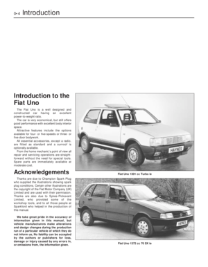 4
4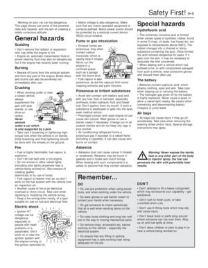 5
5 6
6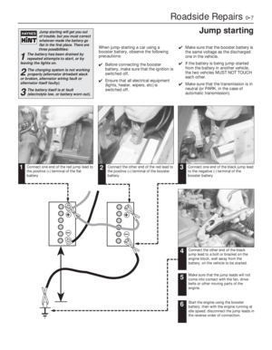 7
7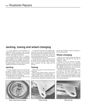 8
8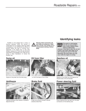 9
9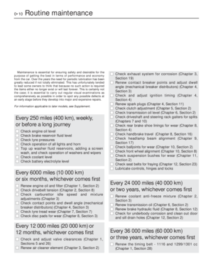 10
10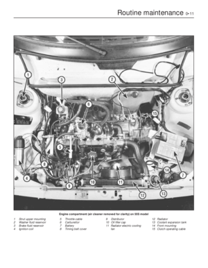 11
11 12
12 13
13 14
14 15
15 16
16 17
17 18
18 19
19 20
20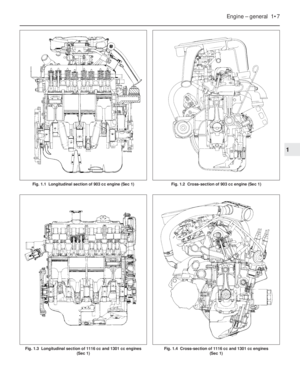 21
21 22
22 23
23 24
24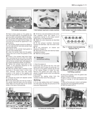 25
25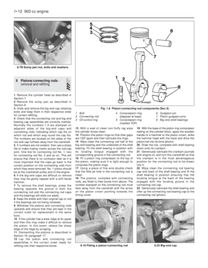 26
26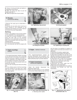 27
27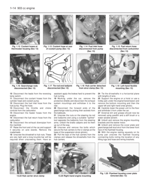 28
28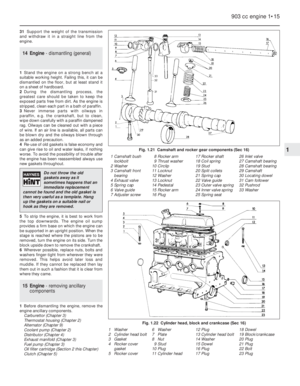 29
29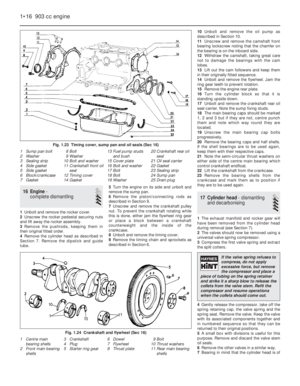 30
30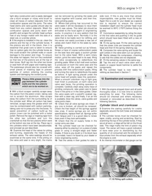 31
31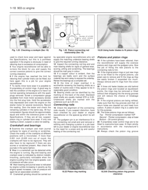 32
32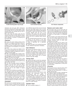 33
33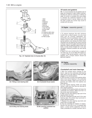 34
34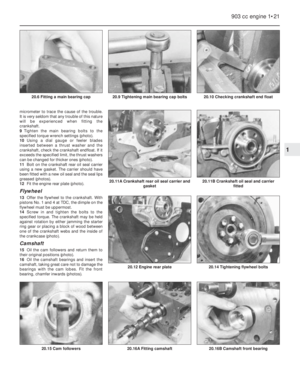 35
35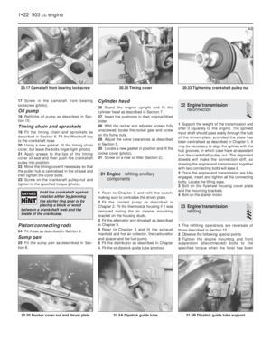 36
36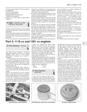 37
37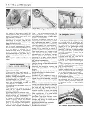 38
38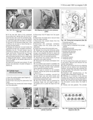 39
39 40
40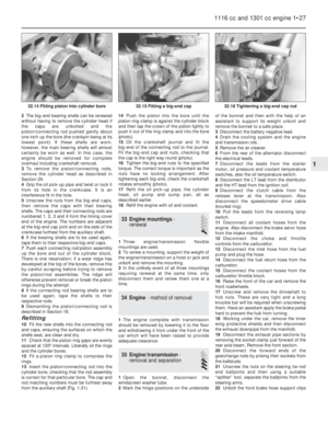 41
41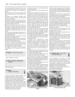 42
42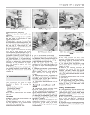 43
43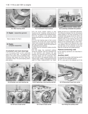 44
44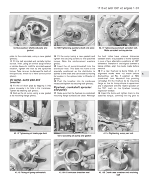 45
45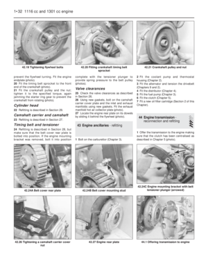 46
46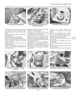 47
47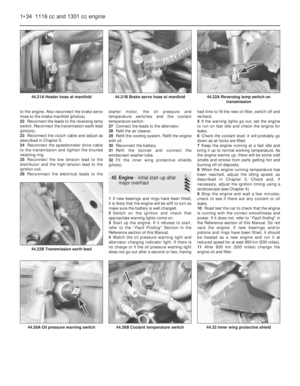 48
48 49
49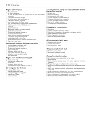 50
50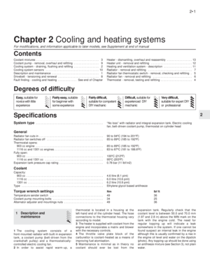 51
51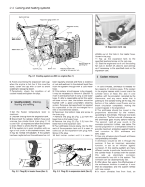 52
52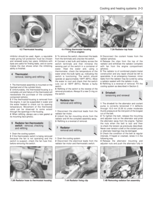 53
53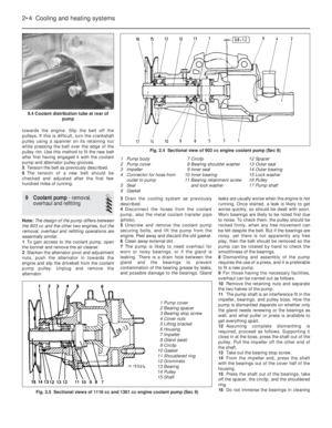 54
54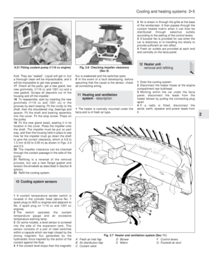 55
55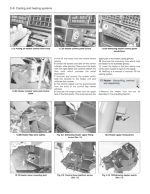 56
56 57
57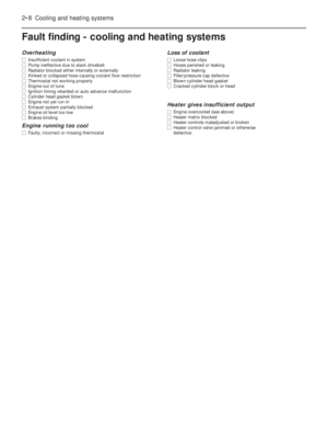 58
58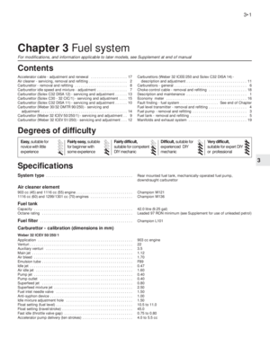 59
59 60
60 61
61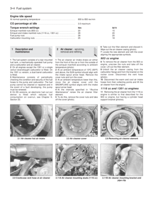 62
62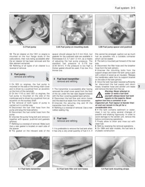 63
63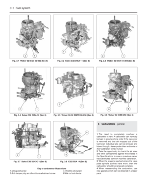 64
64 65
65 66
66 67
67 68
68 69
69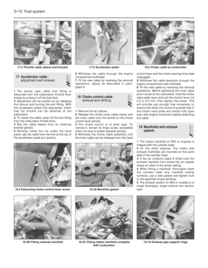 70
70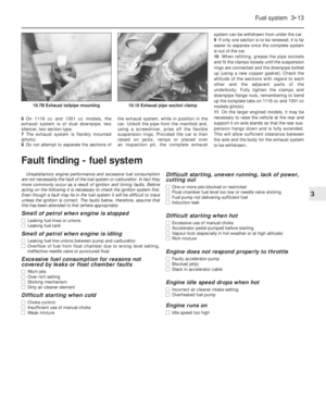 71
71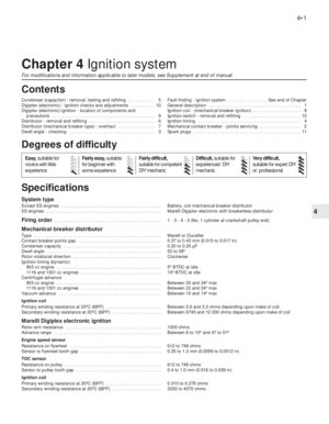 72
72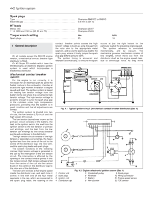 73
73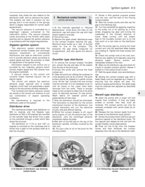 74
74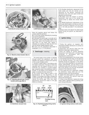 75
75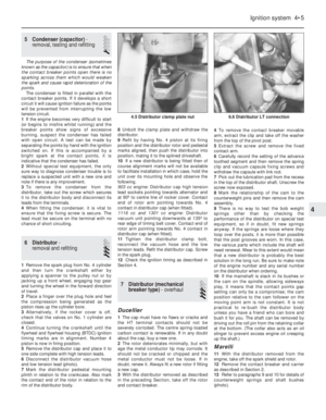 76
76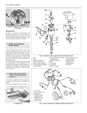 77
77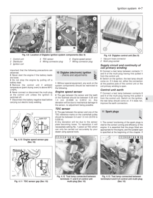 78
78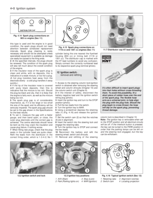 79
79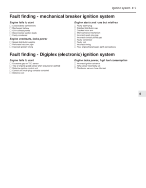 80
80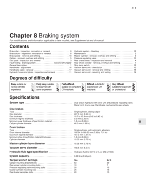 81
81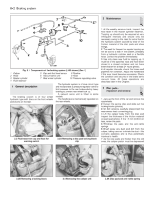 82
82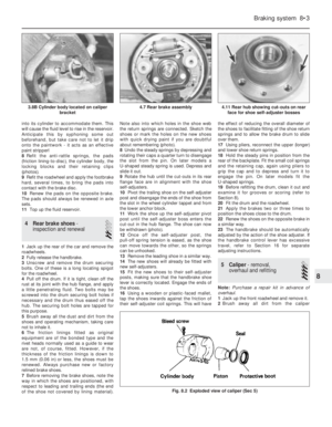 83
83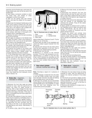 84
84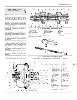 85
85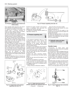 86
86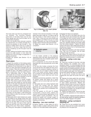 87
87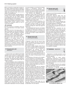 88
88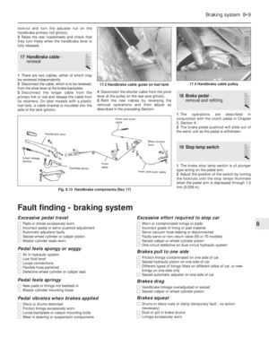 89
89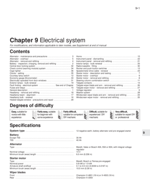 90
90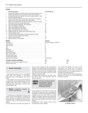 91
91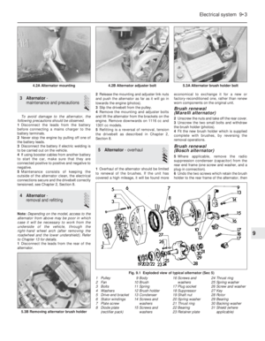 92
92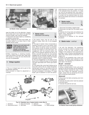 93
93 94
94 95
95 96
96 97
97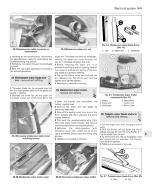 98
98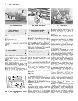 99
99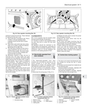 100
100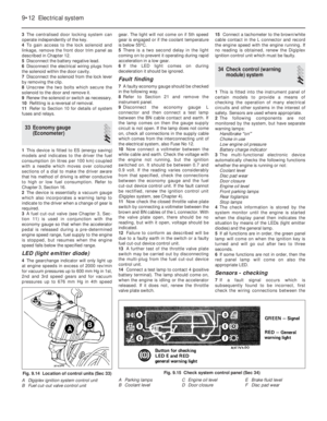 101
101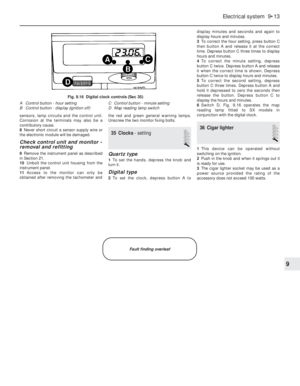 102
102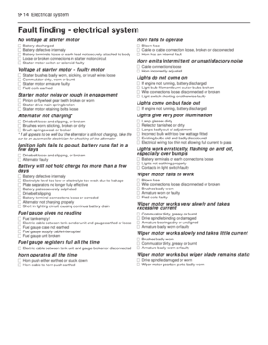 103
103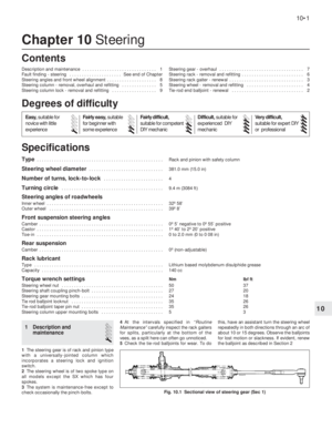 104
104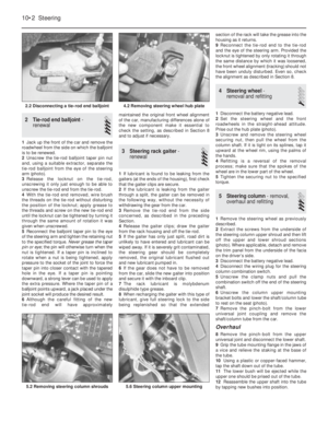 105
105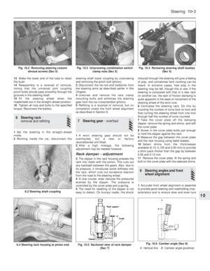 106
106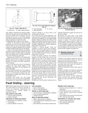 107
107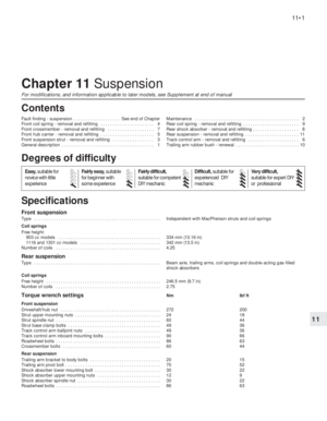 108
108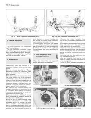 109
109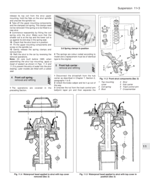 110
110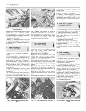 111
111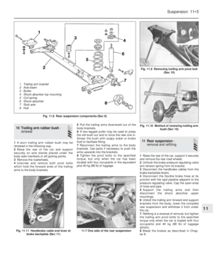 112
112 113
113 114
114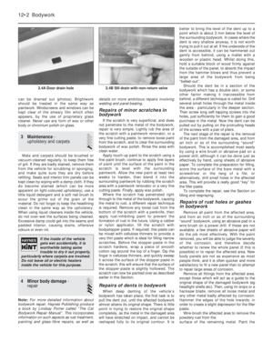 115
115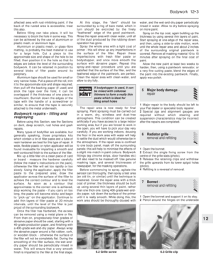 116
116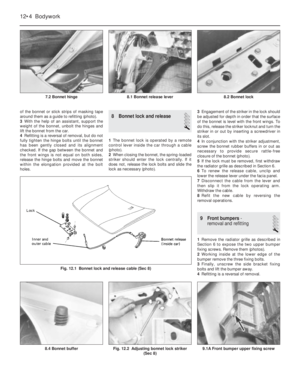 117
117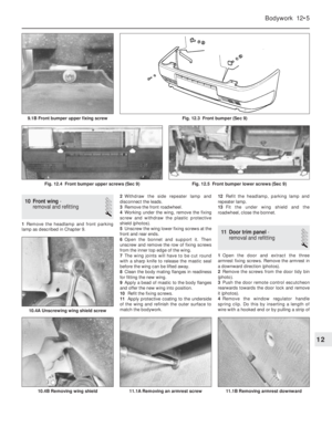 118
118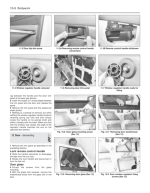 119
119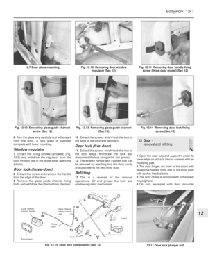 120
120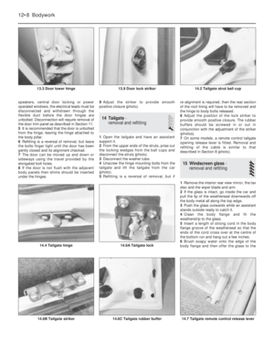 121
121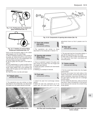 122
122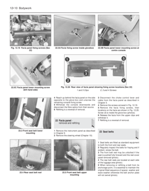 123
123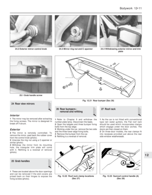 124
124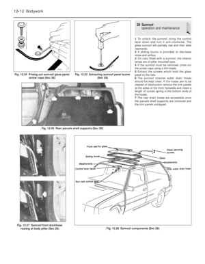 125
125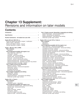 126
126 127
127 128
128 129
129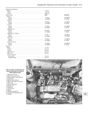 130
130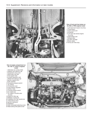 131
131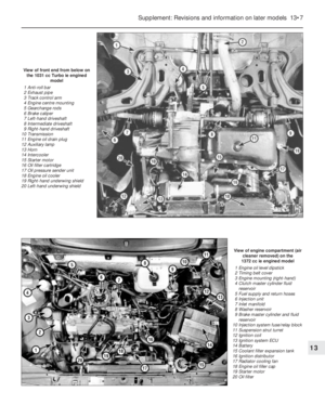 132
132 133
133 134
134 135
135 136
136 137
137 138
138 139
139 140
140 141
141 142
142 143
143 144
144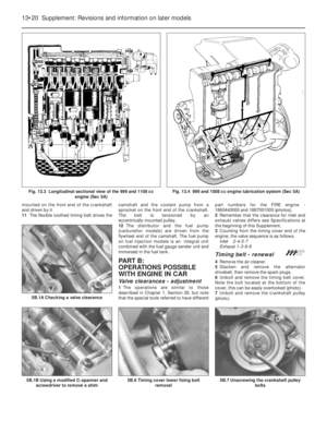 145
145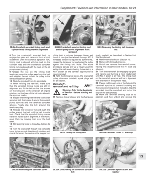 146
146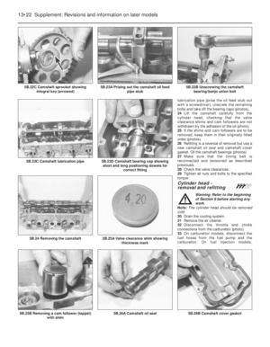 147
147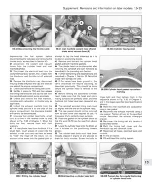 148
148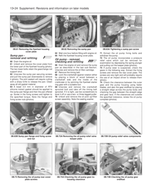 149
149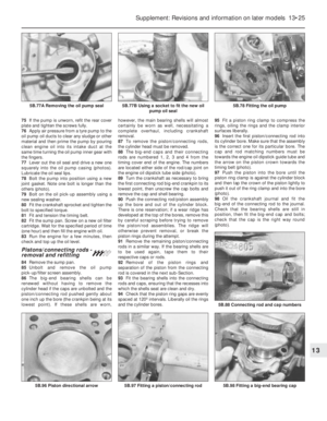 150
150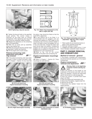 151
151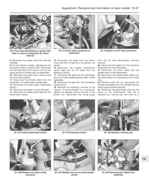 152
152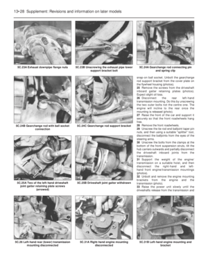 153
153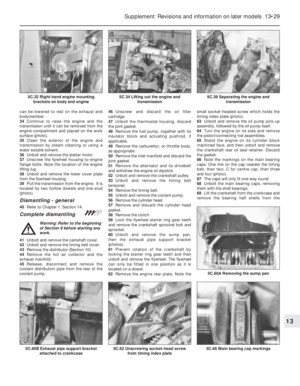 154
154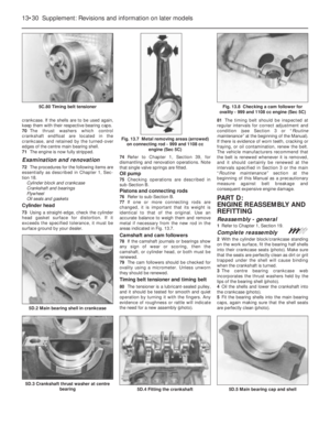 155
155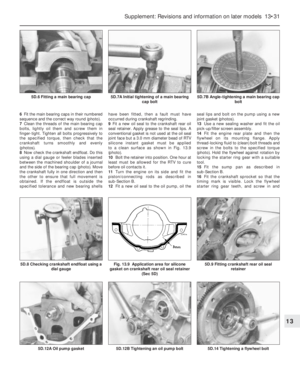 156
156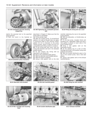 157
157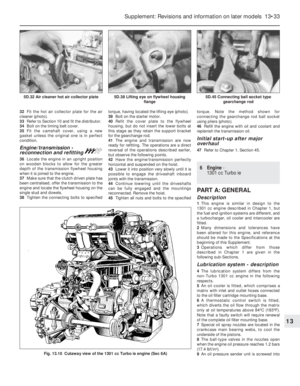 158
158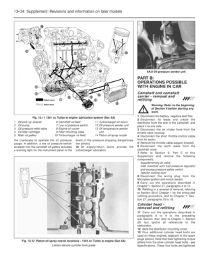 159
159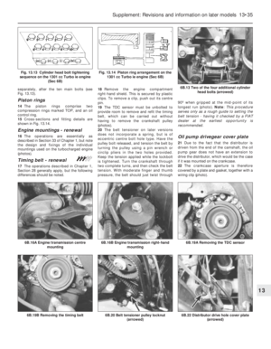 160
160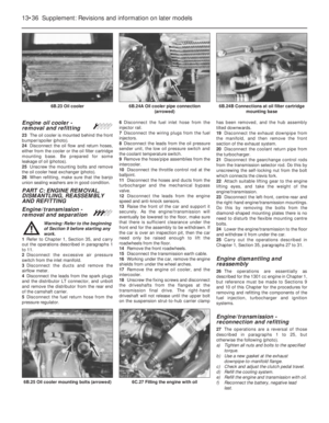 161
161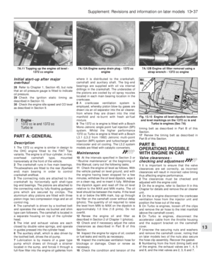 162
162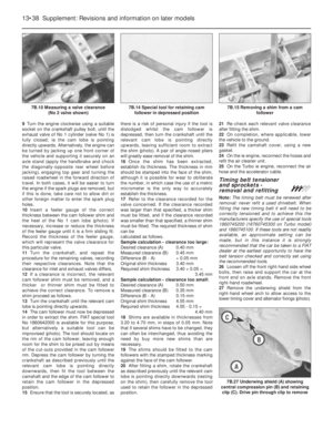 163
163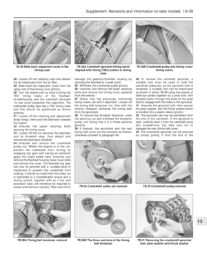 164
164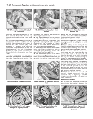 165
165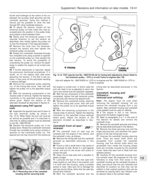 166
166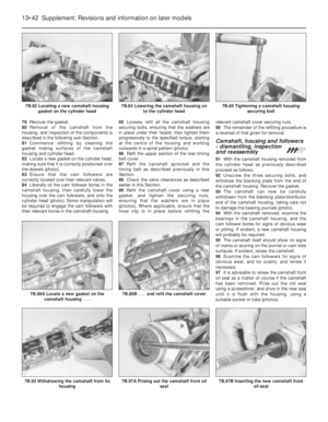 167
167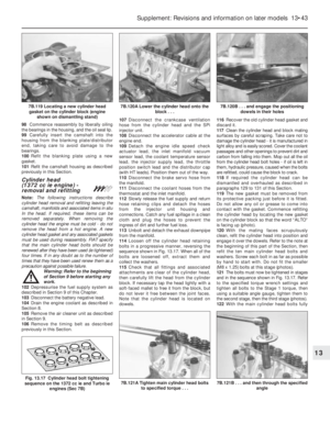 168
168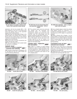 169
169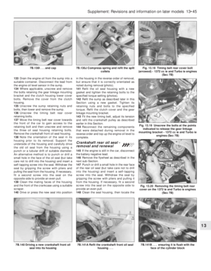 170
170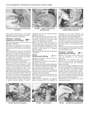 171
171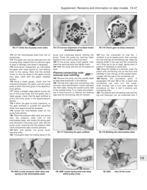 172
172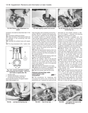 173
173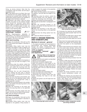 174
174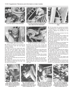 175
175 176
176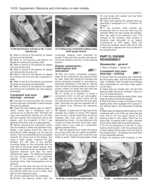 177
177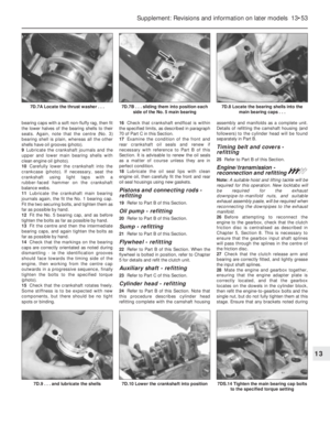 178
178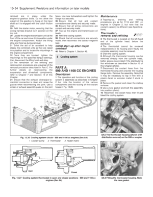 179
179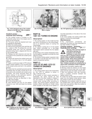 180
180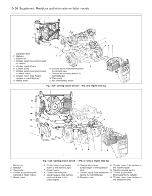 181
181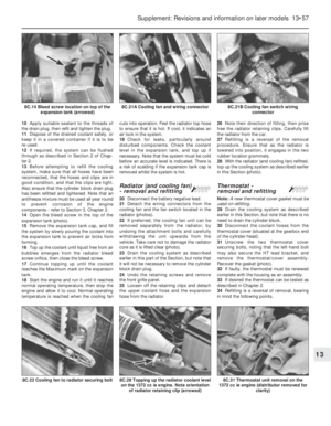 182
182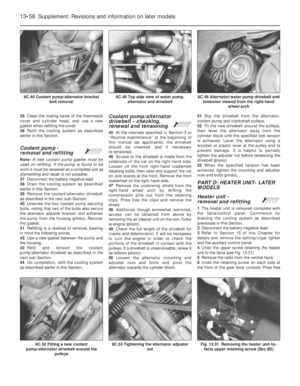 183
183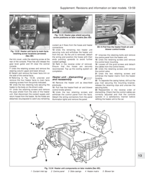 184
184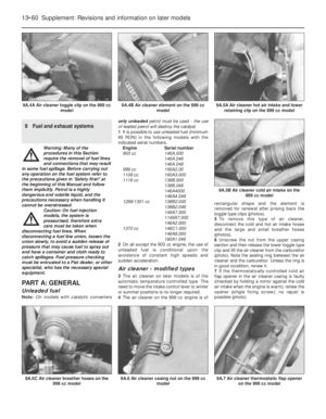 185
185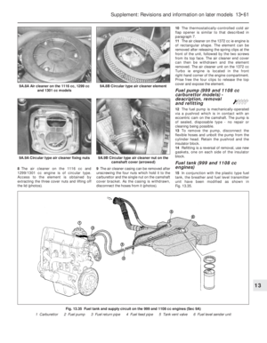 186
186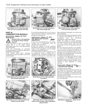 187
187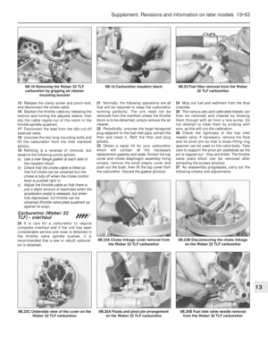 188
188 189
189 190
190 191
191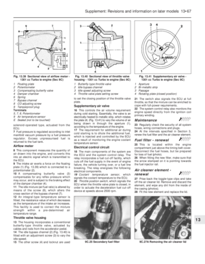 192
192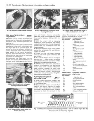 193
193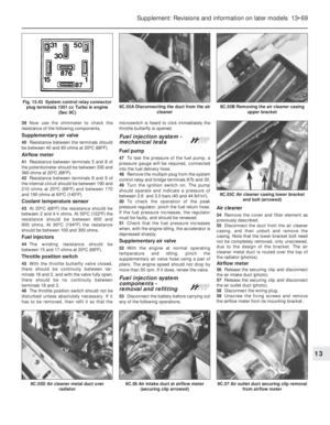 194
194 195
195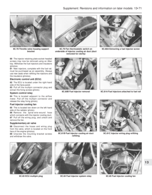 196
196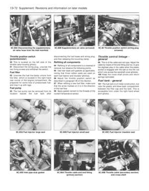 197
197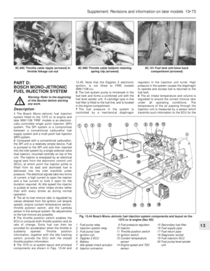 198
198 199
199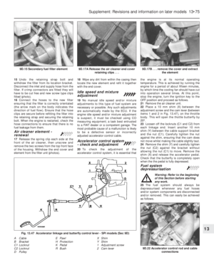 200
200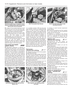 201
201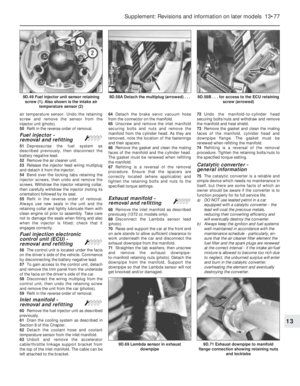 202
202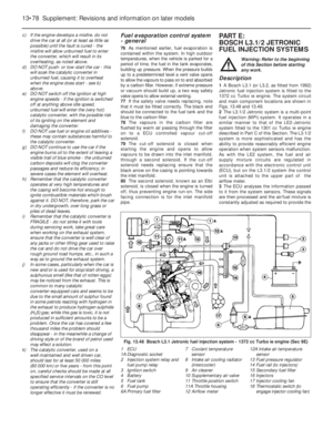 203
203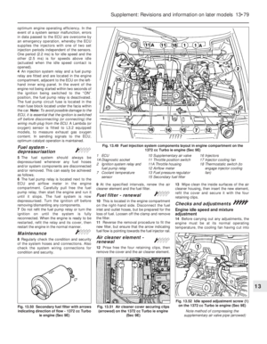 204
204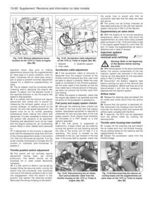 205
205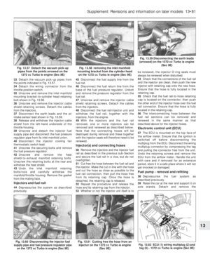 206
206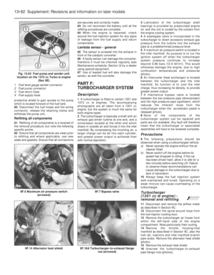 207
207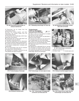 208
208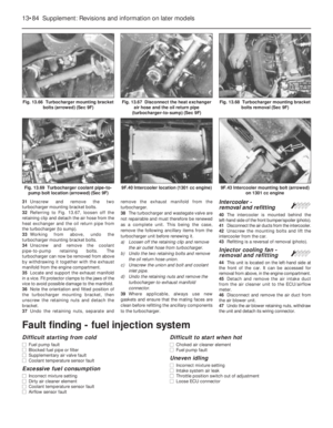 209
209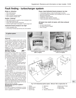 210
210 211
211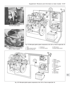 212
212 213
213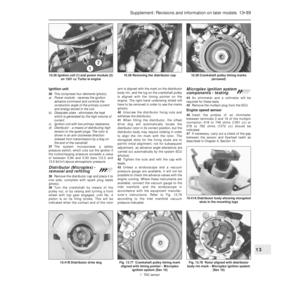 214
214 215
215 216
216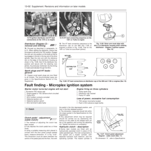 217
217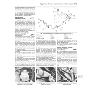 218
218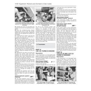 219
219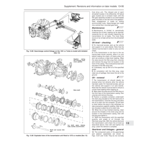 220
220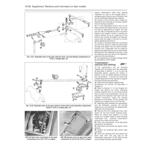 221
221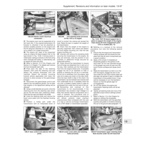 222
222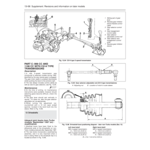 223
223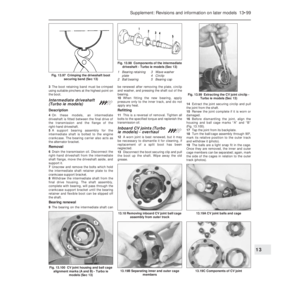 224
224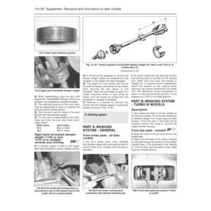 225
225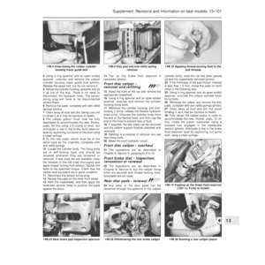 226
226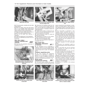 227
227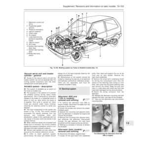 228
228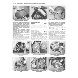 229
229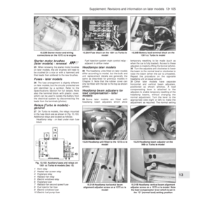 230
230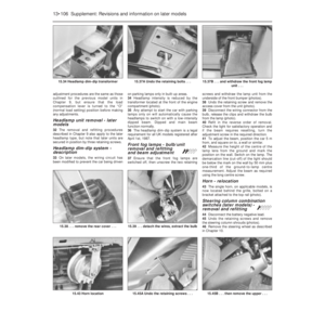 231
231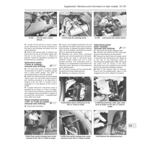 232
232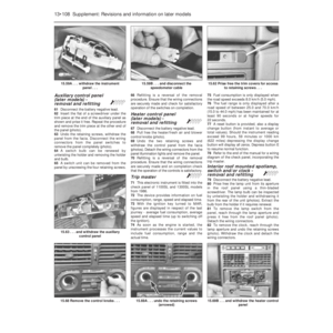 233
233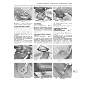 234
234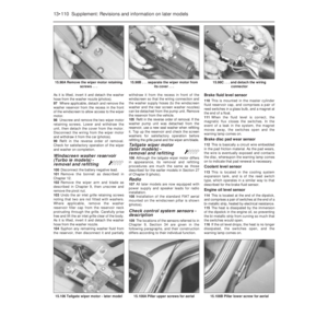 235
235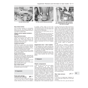 236
236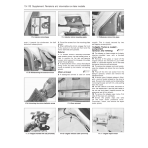 237
237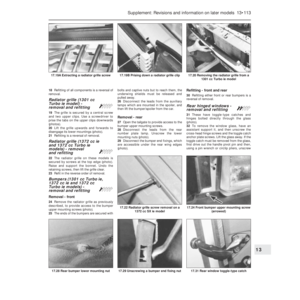 238
238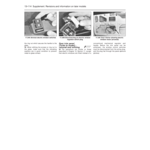 239
239 240
240 241
241 242
242 243
243 244
244 245
245 246
246 247
247 248
248 249
249 250
250 251
251 252
252 253
253 254
254 255
255 256
256 257
257 258
258 259
259 260
260 261
261 262
262 263
263 264
264 265
265 266
266 267
267 268
268 269
269 270
270 271
271 272
272 273
273 274
274 275
275 276
276 277
277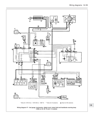 278
278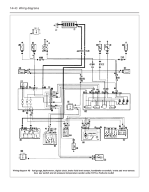 279
279 280
280 281
281 282
282 283
283 284
284 285
285 286
286 287
287 288
288 289
289 290
290 291
291 292
292 293
293 294
294 295
295 296
296 297
297 298
298 299
299 300
300 301
301 302
302