Page 185 of 303

9 Fuel and exhaust systems
Warning: Many of the
procedures in this Section
require the removal of fuel lines
and connections that may result
in some fuel spillage. Before carrying out
any operation on the fuel system refer to
the precautions given in ‘Safety first!’ at
the beginning of this Manual and follow
them implicitly. Petrol is a highly
dangerous and volatile liquid, and the
precautions necessary when handling it
cannot be overstressed.
Caution: On fuel injection
models, the system is
pressurised, therefore extra
care must be taken when
disconnecting fuel lines. When
disconnecting a fuel line union, loosen the
union slowly, to avoid a sudden release of
pressure that may cause fuel to spray out
and have a container and cloth ready to
catch spillages. Fuel pressure checking
must be entrusted to a Fiat dealer, or other
specialist, who has the necessary special
equipment.
PART A: GENERAL
Unleaded fuel
Note: On models with catalytic convertersonly unleaded petrol must be used - the use
of leaded petrol will destroy the catalyst.
1It is possible to use unleaded fuel (minimum
95 RON) in the following models with the
indicated serial numbers.
Engine Serial number
903 cc 146A.000
146A.046
146A.048
999 cc 156A2.00
1108 cc 160A3.000
1116 cc 138B.000
138B.046
146A4000
146A4.048
1299/1301 cc 138B2.000
138B2.046
149A7.000
1149A7.000
146A2.000
1372 cc 146C1.000
146A8.000
160A1.046
2On all except the 903 cc engine, the use of
unleaded fuel is conditional upon the
avoidance of constant high speeds and
sudden acceleration.
Air cleaner - modified types
3The air cleaner on later models is of the
automatic temperature controlled type. The
need to move the intake control lever to winter
or summer positions is no longer required.
4The air cleaner on the 999 cc engine is ofrectangular shape and the element is
removed for renewal after prising back the
toggle type clips (photos).
5To remove this type of air cleaner,
disconnect the cold and hot air intake hoses
and the large and small breather hoses
(photos).
6Unscrew the nut from the upper casing
section and then release the lower toggle type
clip and lift the air cleaner from the carburettor
(photo). Note the sealing ring between the air
cleaner and the carburettor. Unless the ring is
in good condition, renew it.
7If the thermostatically-controlled cold air
flap opener in the air cleaner casing is faulty
(checked by holding a mirror against the cold
air intake when the engine is warm), renew the
opener (single fixing screw); no repair is
possible (photo).
13•60 Supplement: Revisions and information on later models
9A.7 Air cleaner thermostatic flap opener
on the 999 cc model9A.6 Air cleaner casing nut on the 999 cc
model9A.5C Air cleaner breather hoses on the
999 cc model
9A.5B Air cleaner cold air intake on the
999 cc model
9A.5A Air cleaner hot air intake and lower
retaining clip on the 999 cc model9A.4B Air cleaner element on the 999 cc
model9A.4A Air cleaner toggle clip on the 999 cc
model
Page 186 of 303
.9The air cleaner casi")
8The air cleaner on the 1116 cc and
1299/1301 cc engine is of circular type.
Access to the element is obtained by
extracting the three cover nuts and lifting off
the lid (photos).9The air cleaner casing can be removed after
unscrewing the four nuts which hold it to the
carburettor and the single nut on the camshaft
cover bracket. As the casing is withdrawn,
disconnect the hoses from it (photos).10The thermostatically-controlled cold air
flap opener is similar to that described in
paragraph 7.
11The air cleaner on the 1372 cc ie engine is
of rectangular shape. The element can be
removed after releasing the spring clips at the
front of the unit, followed by the two screws
from its top face. The air cleaner end cover
can then be withdrawn and the element
removed. The air cleaner unit on the 1372 cc
Turbo ie engine is located in the front
right-hand corner of the engine compartment.
Prise free the four clips to release the top
cover and expose the element.
Fuel pump (999 and 1108 cc
carburettor models) -
description, removal
and refitting
Á
12The fuel pump is mechanically-operated
via a pushrod which is in contact with an
eccentric cam on the camshaft. The pump is
of sealed, disposable type - no repair or
cleaning being possible.
13To remove the pump, disconnect the
flexible hoses and unbolt the pump from the
cylinder head. Retain the pushrod and the
insulator block.
14Refitting is a reversal of removal, use new
gaskets, one on each side of the insulator
block.
Fuel tank (999 and 1108 cc
engines)
15In conjunction with the plastic type fuel
tank, the breather and fuel level transmitter
unit have been modified as shown in
Fig. 13.35.
Supplement: Revisions and information on later models 13•61
9A.9A Circular type air cleaner fixing nuts9A.9B Circular type air cleaner nut on the
camshaft cover (arrowed)
9A.8B Circular type air cleaner element9A.8A Air cleaner on the 1116 cc, 1299 cc
and 1301 cc models
Fig. 13.35 Fuel tank and supply circuit on the 999 and 1108 cc engines (Sec 9A)
1 Carburettor 2 Fuel pump 3 Fuel return pipe 4 Fuel feed pipe 5 Tank vent valve 6 Fuel level sender unit
13
Page 187 of 303
 -
description
Warning: Refer to the beginning
of this Section before starting
any work.
1This carburettor is used on the 999 cc
engine and is of")
PART B:
CARBURETTOR MODELS
Carburettor (Weber 32 TLF) -
description
Warning: Refer to the beginning
of this Section before starting
any work.
1This carburettor is used on the 999 cc
engine and is of the single venturi
downdraught type, with a manually-operated
choke (cold start).
2The unit incorporates an automatic
anti-flooding device, a full power valve and an
accelerator pump (photos).
3The throttle valve block, although
incorporating coolant hose stubs, is not in fact
coolant-heated.4A solenoid-operated idle cut-off valve is
fitted to prevent running-on (dieseling) when
the ignition is switched off.
Carburettor (Weber 32 TLF) -
idle speed and mixture
adjustment
¢
5If the car is not equipped with a rev counter,
connect one in accordance with the
manufacturer’s instructions.
6Have the engine at normal operating
temperature and idling. Turn the idle speed
screw on the carburettor until the speed
matches that specified (photo).
7The idle mixture is set in production, and
the adjustment screw is sealed with a
tamperproof cap. If, however, the idling is not
smooth or the engine or carburettor havebeen extensively overhauled, the mixture may
require adjusting.
8Prise out the tamperproof plug and connect
an exhaust gas analyser to the car in
accordance with the instrument
manufacturer’s instructions (photo).
9With the engine at normal operating
temperature and idling at the specified speed,
turn the mixture screw until the CO
percentage is within the specified tolerance
(photo).
10If an exhaust gas analyser is not available,
turn the mixture screw anti-clockwise to
obtain maximum idle speed and then turn it
clockwise until the speed just starts to drop.
Re-adjust the idle speed screw to bring the
idle speed to the specified level.
11Switch off the engine and remove the test
instruments. It is advisable to fit a new
tamperproof cap to the mixture screw if it is
intended to take the vehicle overseas. This is
required to meet legislation in certain
countries.
Carburettor (Weber 32 TLF)
- removal and refitting ª
12Remove the air cleaner.
13Release the clips and disconnect the fuel
hoses from the carburettor. Take extreme
care that fuel spillage is contained and that
there are no naked flames in the vicinity of the
work area. Do not smoke.
14Disconnect the distributor vacuum hose
from the carburettor.
13•62 Supplement: Revisions and information on later models
9B.9 Mixture adjustment - Weber 32 TLF
carburettor9B.8 Weber 32 TLF 4/250 carburettor
mixture screw location under tamperproof
plug (arrowed)9B.6 Weber 32 TLF 4/250 carburettor idle
speed screw (arrowed)
9B.2E Weber 32 TLF 4/250 carburettor
from above9B.2D Weber 32 TLF 4/250 carburettor
from throttle linkage side
9B.2C Weber 32 TLF 4/250 carburettor
from accelerator pump side9B.2B Weber 32 TLF 4/250 carburettor
from choke linkage side9B.2A Weber 32 TLF 4/250 carburettor
from anti-run-on solenoid valve side
Page 188 of 303

15Release the clamp screw and pinch-bolt,
and disconnect the choke cable.
16Slacken the throttle cable by releasing the
locknut and turning the adjuster sleeve, then
slip the cable nipple out of the notch in the
throttle spindle quadrant.
17Disconnect the lead from the idle cut-off
solenoid valve.
18Unscrew the two long mounting bolts and
lift the carburettor from the inlet manifold
(photo).
19Refitting is a reversal of removal, but
observe the following points (photo).
a) Use a new flange gasket at each side of
the insulator block.
b) Check that the choke cable is fitted so
that full choke can be obtained but the
choke is fully off when the choke control
lever is pushed right in.
c) Adjust the throttle cable so that there is
just a slight amount of slackness when the
accelerator pedal is released, but when
fully depressed, full throttle can be
obtained (throttle valve plate quadrant up
against its stop).
Carburettor (Weber 32
TLF) - overhaul¢
20It is rare for a carburettor to require
complete overhaul and if the unit has seen
considerable service and wear is detected in
the throttle valve spindle bushes, it is
recommended that a new or rebuilt carburet-
tor is obtained.21Normally, the following operations are all
that will be required to keep the carburettor
working perfectly. The unit need not be
removed from the manifold unless the throttle
block is to be detached; simply remove the air
cleaner.
22Periodically, unscrew the large hexagonal
plug adjacent to the fuel inlet pipe, extract the
filter and clean it. Refit the filter and plug
(photo).
23Obtain a repair kit for your carburettor
which will contain all the necessary
replacement gaskets and seals. Extract the top
cover and choke diaphragm assembly fixing
screws, remove the small plastic cover and
push out the bush, then lift the top cover from
the carburettor. Discard the gasket (photos).24Mop out fuel and sediment from the float
chamber.
25The various jets and calibrated bleeds can
then be removed and cleared by blowing
them through with air from a tyre pump. Do
not attempt to clear them by probing with
wire, as this will ruin the calibration.
26Check the tightness of the fuel inlet
needle valve. If necessary, remove the float
and its pivot pin so that a close-fitting ring
spanner can be used on the valve body. Take
care to support the pivot pin pedestals as the
pin is tapped out - they are brittle. The throttle
valve plate block can be removed after
extracting the screws (photos).
27As reassembly progresses, carry out the
following checks and adjustments.
Supplement: Revisions and information on later models 13•63
9B.22 Fuel filter removal from the Weber
32 TLF carburettor9B.19 Carburettor insulator block9B.18 Removing the Weber 32 TLF
carburettor by gripping air cleaner
mounting bracket
9B.26B Fuel inlet valve needle removal
from the Weber 32 TLF carburettor9B.26A Floats and pivot pin arrangement
on the Weber 32 TLF carburettor
9B.23B Disconnecting the choke linkage
on the Weber 32 TLF carburettor9B.23A Choke linkage cover removal from
the Weber 32 TLF carburettor
9B.23C Underside view of the cover on the
Weber 32 TLF carburettor
13
Page 189 of 303

Float level - checking and adjustment
28With the carburettor top cover held
vertically so that the float arm just touches the
fuel inlet needle valve ball, measure between
the float and the surface of the flange gasket
as shown in Fig. 13.36. If the dimension is not
within the specified tolerance, bend the float
tab which bears on the needle valve ball.
Fast idle - adjustment (requires
removal of the carburettor)
29Close the choke valve plate by moving the
control lever fully. Retain the lever in this
position with a rubber band.
30The throttle valve plate should now be
open to give a gap between its edge and the
progression holes as specified. Check the gap
using a twist drill of equivalent diameter.
31If adjustment is required, release the
locknut and turn the adjustment screw.
Retighten the locknut.
Automatic anti-flooding device -
adjustment
32Operate the choke valve plate lever fully.
33Move the control lever on the automatic
anti-flooding device downwards to simulate
vacuum pull-down. The choke butterfly
should open, leaving a gap (B - Fig 13.38) as
specified. Measure the gap with a twist drill of
equivalent diameter and make sure that the
choke valve plate is in the position shown. If
adjustment is required, turn the screw on the
diaphragm unit.
Carburettor
(Weber 30/32 DMTE) - general
34The carburettor is of twin barrel
downdraught type with a manually-operated
choke and an electronic fuel cut-off overrun
valve (photos).
35Periodically, remove the large hexagonal
plug from its location at the fuel inlet pipe
stubs, and clean any dirt from the filter gauge.
13•64 Supplement: Revisions and information on later models
Fig. 13.37 Fast idle adjustment -
Weber 32 TLF carburettor (Sec 9B)
A = 0.65 to 0.75 mm (0.026 to 0.030 in)Fig. 13.38 Automatic anti-flooding device
adjustment - Weber 32 TLF carburettor
(Sec 9B)
B = 4.5 mm (0.18 in)Fig. 13.36 Float level measurement -
Weber 32 TLF carburettor (Sec 9B)
A = 26.75 to 27.25 mm (1.05 to 1.07 in)
9B.26F Main parts of the Weber 32 TLF
carburettor
9B.26E Throttle valve block gasket on the
Weber 32 TLF carburettor9B.26D Extracting the throttle valve block
screws from the Weber 32 TLF carburettor9B.26C Fuel inlet valve body and washer
removal from the Weber 32 TLF
carburettor
9B.34A Weber 30/32 DMTE carburettor
from anti-flood device link side
Page 190 of 303
.
Removal and refitting
37The operations are similar to those
described for the Weber 32 TLF earlier in this
Supplement, but")
Idle speed and mixture adjustment
36Refer to Chapter 3, Section 7 (photos).
Removal and refitting
37The operations are similar to those
described for the Weber 32 TLF earlier in this
Supplement, but note that the carburettor is
secured by four nuts and additional electrical
leads must be disconnected (photos).
Carburettor (Weber 30/32
DMTE) - overhaul¢
38The carburettor top cover with float may
be removed without the need to withdraw the
carburettor from the manifold. Other
Supplement: Revisions and information on later models 13•65
9B.34D Weber 30/32 DMTE carburettor
from throttle link side9B.34C Weber 30/32 DMTE carburettor
from choke link side9B.34B Weber 30/32 DMTE carburettor
from diaphragm hose side
9B.37E Carburettor lead connectors on the
Weber 30/32 DMTE carburettor9B.37D Electrical lead to automatic anti-
flood device on the Weber 30/32 DMTE
carburettor9B.37C Choke cable connection on the
Weber 30/32 DMTE carburettor
9B.37B Throttle cable connection on the
Weber 30/32 DMTE carburettor9B.37A Fuel inlet and return hoses on the
Weber 30/32 DMTE carburettor
9B.36A Showing idle speed screw
(arrowed) and . . .9B.34E Weber 30/32 DMTE carburettor
from above (with cover removed)
9B.36B . . . mixture screw (arrowed) on the
Weber 30/32 DMTE carburettor
13
Page 191 of 303

adjustments described in this sub-Section,
however, will require removal of the
carburettor.
39Disconnect the short, curved diaphragm
hose from the top cover.
40Extract the top cover screws, lift the cover
from the carburettor body, and rotate it in
order to release the cranked choke control
rod from its key hole (photo). Mop out the fuel
and clean the jets.
41Check the jet sizes and other components
against those listed in the Specifications, in
case a previous owner has substituted
incorrect components (photo).
42Overhaul procedures are generally as
given in Chapter 3, Section 14 for the Weber
30/32 DMTR, but use the Specifications listed
in this Chapter. Additional overhaul
procedures are given here.
Fuel inlet needle valve
43If a high float level causing flooding of the
carburettor has been evident, first check that
the inlet valve housing is tight, and its washer
is sealing satisfactorily. A leak here will cause
fuel to bypass the inlet valve.
44If the needle valve is to be renewed,
remove it in the following way.
45Access to the fuel inlet needle valve is
obtained by carefully tapping out the float arm
pivot pin. Take care, the pivot pin pillars are
very brittle (photo).
46Unscrew the fuel inlet valve body and
remove the valve and washer.47When refitting the new valve, always use a
new sealing washer.
Float stroke (travel) - see Fig. 3.10
48The float stroke should be between 42.5
and 43.5 mm when measured from the top
cover gasket. Adjust if necessary by bending
the tab on the end of the arm.
Accelerator pump
49Adjustment of the accelerator pump is
very rarely required, but if performance is
suspect, carry out the following operations.
50Fill the carburettor float chamber and then
operate the throttle valve plate lever several
times to prime the pump.
51Position a test tube under the accelerator
pump jet and give ten full strokes of the
throttle lever, pausing between each stroke to
allow fuel to finish dripping.
52The total volume of fuel collected should
be as specified. Adjust the nut on the pump
control if necessary to increase or decrease
the volume of fuel ejected.
General
53When the stage is reached where the
valve plate spindle bushes have worn, then
the carburettor should be renewed complete.
54When reassembling the carburettor, use
new gaskets which can be obtained in a repair
pack.
Carburettor (Weber 32 ICEV
61/250 and DMTE 30/32,
DMTE 30/150) - general
55These carburettor types are fitted to later
models according to engine type. They are
similar in structure and operation to their
equivalents described in Chapter 3. Reference
can therefore be made to that Chapter for the
description and any operations concerning
them, but refer to Section 2 of this Chapter for
their specifications.
Carburettor (Solex
C 30/32-CIC 8) - description
56This carburettor is fitted as an alternative
to the Weber unit on 1116 cc models
produced for certain markets. The removal,
refitting and overhaul procedures are
essentially the same as described earlier for
the Weber carburettors.
PART C:
BOSCH LE2-JETRONIC
FUEL INJECTION SYSTEM
Description
Warning: Refer to the beginning
of this Section before starting
any work.
1The Bosch LE2-Jetronic fuel injection
system, fitted to the 1301 cc Turbo ie model,
is an electronically controlled multi-point
injection (MPi) system.
2The fuel injectors are fed at constant
pressure in relation to inlet manifold vacuum
pressure.
3The system electronic control unit (ECU)
actuates the injectors for variable duration,
and so supplies the precise volume of fuel
required for any given engine speed and load
condition.
4The ECU also monitors the air induction, air
temperature, coolant temperature and throttle
opening as additional parameters to compute
the required opening of the fuel injectors,
giving maximum power with fuel economy.
Fuel supply system
5The fuel supply system consists of an
electric pump and primary filter, located
adjacent to the fuel tank. A fuel pressure peak
damper is located next to the pump (photo).
6Fuel is then pumped through a filter to the
fuel rail and injectors. The injectors are of the
13•66 Supplement: Revisions and information on later models
9C.5 Electric fuel pump/filter/pressure
damper assembly location on a 1301 cc
Turbo ie model
9B.41 Jets on the Weber 30/32 DMTE
carburettor (top cover removed)
9B.45 Float pivot arrangement and needle
valve on the Weber 30/32 DMTE
carburettor
9B.40 Unscrewing a top cover screw from
the Weber 30/32 DMTE carburettor9B.37F Unscrewing a carburettor fixing nut
Page 192 of 303

solenoid-operated type, actuated from the
ECU.
7Fuel pressure is regulated according to inlet
manifold vacuum pressure by a fuel pressure
regulator. Excess unpressurised fuel is
returned to the fuel tank.
Airflow meter
8This component measures the quantity of
air drawn into the engine, and converts this
into an electric signal which is transmitted to
the ECU.
9The intake air exerts a force on the floating
plate (1) (Fig. 13.39) which is connected to a
potentiometer (2).
10A compensating butterfly valve (3)
compensates for any reflex pressure which
may occur, and is subject to the braking effect
of the damper chamber (4).
11The idle mixture (air/fuel ratio) is altered by
means of the screw (8), which alters the
cross-section of the bypass channel (7).
12An integral-type temperature sensor is
fitted, the resistance value of which decreases
as the temperature of the intake air increases.
This facility is used to correct the mixture
strength within a pre-determined air
temperature range.
Throttle valve housing
13The housing incorporates a conventional
butterfly-type throttle valve, actuated by
cables and rods from the accelerator pedal.
14The idle bypass channel (2) (Fig. 13.40) is
fitted with an adjustment screw (3) to vary the
idle speed.
15The other screw (4) and locknut are usedto set the closing position of the throttle valve
plate.
Supplementary air valve
16This controls the air volume requirement
during cold starting. Essentially, the valve is an
electrically-heated bi-metallic strip, which rotates
the plate (4) (Fig. 13.41) to vary the volume of air
being drawn in through the aperture (1),
according to the temperature of the engine.
17The requirement for additional air during
cold starting is to dilute the additional fuel,
which is injected and controlled by the ECU
as a result of monitoring the engine coolant
temperature sensor.
Electrical control circuit
18The main components of the system are
the ECU and the system control relay. The
relay incorporates a fuel cut-off facility, which
cuts off the fuel supply in the event of engine
failure, the vehicle turning over, or a fuel line
breaking. The relay energises the following
electrical components.
19Coolant temperature sensor, which
signals the coolant temperature to the ECU.
20Throttle position switch, which signals the
ECU when the throttle valve plate is closed, in
order to actuate the deceleration fuel cut-off
device at speeds above 2500 rpm.21The switch also signals the ECU at full
throttle, so that the mixture can be enriched to
cope with full-power requirements.
22The system control relay also monitors the
engine speed directly from the ignition coil
primary winding.
MaintenanceÁ
23Regularly check the security of all system
hoses, wiring connections and plugs.
24At the intervals specified in Section 3,
renew the fuel filter and the air cleaner element.
Fuel filter - renewalÁ
25This is located within the engine
compartment just above the timing belt cover.
Disconnect the fuel hoses, but be prepared
for loss of fuel (photo).
26When fitting the new filter, make sure that
the arrow stamped on it is pointing towards
the fuel injector rail.
Air cleaner element -
renewal
Á
27Prise back the toggle-type clips and take
off the air cleaner lid. Remove and discard the
element, and wipe any dirt from the inside of
the casing (photos).
28Fit the new element and replace the lid.
Supplement: Revisions and information on later models 13•67
Fig. 13.41 Supplementary air valve -
1301 cc Turbo ie engine (Sec 9C)
1 Aperture
2 Bi-metallic strip
3 Passage
4 Rotating plate (closed position)Fig. 13.40 Sectional view of throttle valve
housing - 1301 cc Turbo ie engine (Sec 9C)
1 Butterfly-type throttle valve
2 Idle bypass channel
3 Idle speed adjusting screw
4 Throttle valve plate setting screwFig. 13.39 Sectional view of airflow meter -
1301 cc Turbo ie engine (Sec 9C)
1 Floating plate
2 Potentiometer
3 Compensating butterfly valve
4 Damper chamber
6 Spring
7 Bypass channel
8 CO adjusting screw
9 Tamperproof plug
Terminals
5, 7, 8, Potentiometer
9 Air temperature sensor
E Sealed (not to be touched)
9C.27A Removing the air cleaner lid9C.25 Secondary fuel filter
13
 1
1 2
2 3
3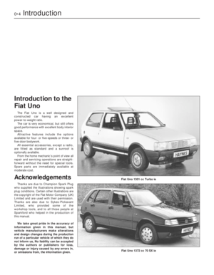 4
4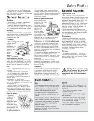 5
5 6
6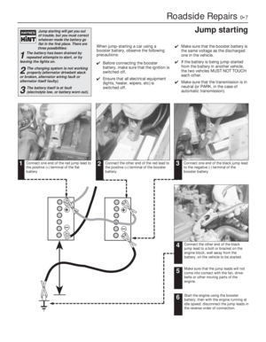 7
7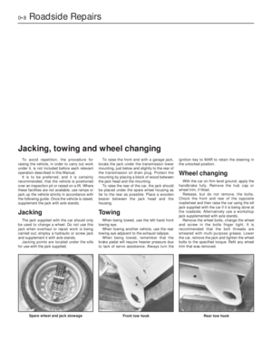 8
8 9
9 10
10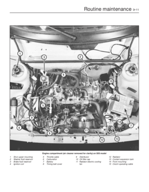 11
11 12
12 13
13 14
14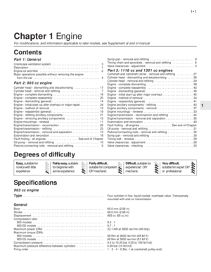 15
15 16
16 17
17 18
18 19
19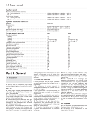 20
20 21
21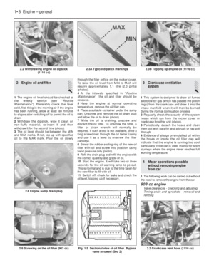 22
22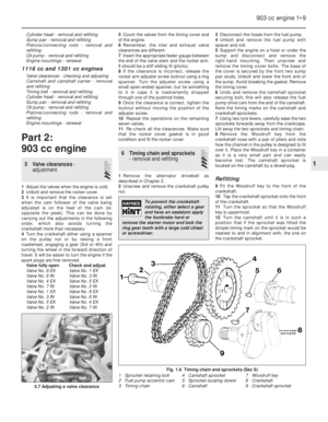 23
23 24
24 25
25 26
26 27
27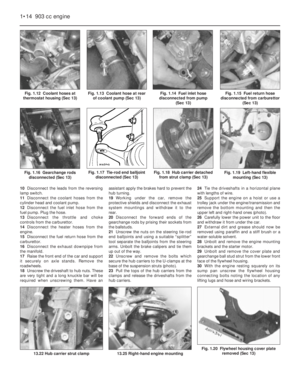 28
28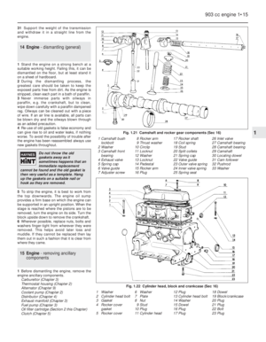 29
29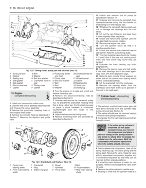 30
30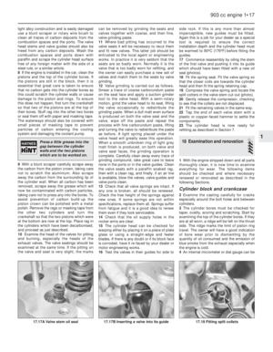 31
31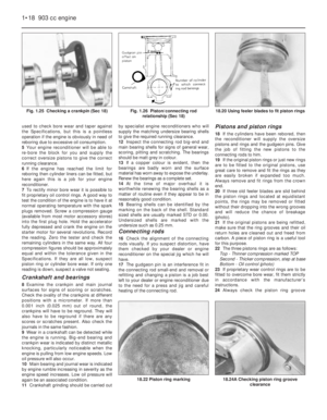 32
32 33
33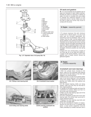 34
34 35
35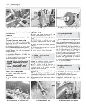 36
36 37
37 38
38 39
39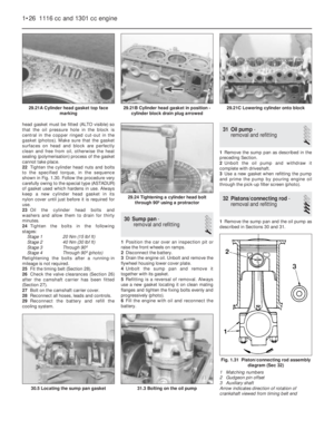 40
40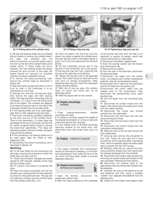 41
41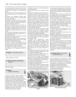 42
42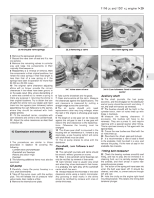 43
43 44
44 45
45 46
46 47
47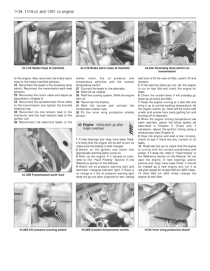 48
48 49
49 50
50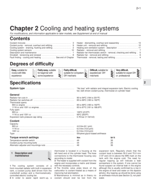 51
51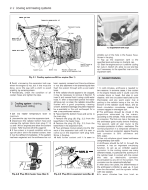 52
52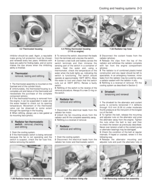 53
53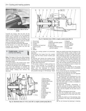 54
54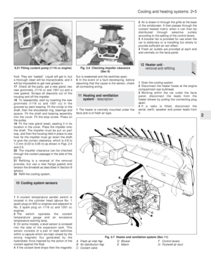 55
55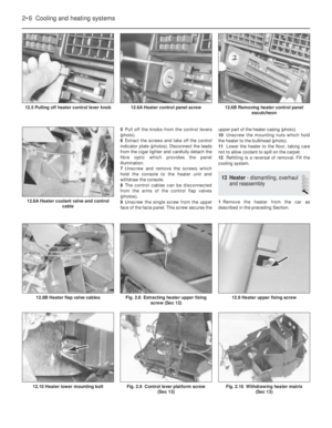 56
56 57
57 58
58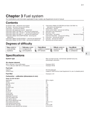 59
59 60
60 61
61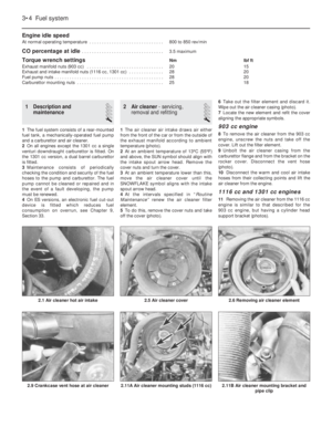 62
62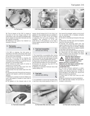 63
63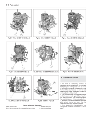 64
64 65
65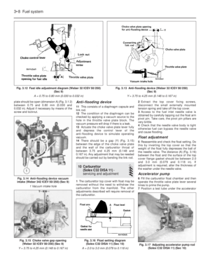 66
66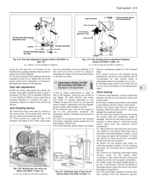 67
67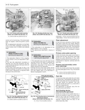 68
68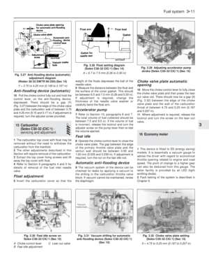 69
69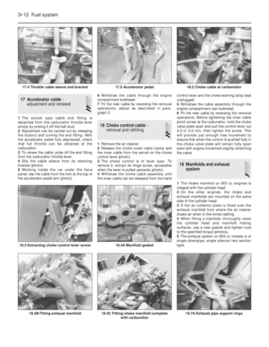 70
70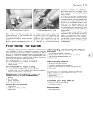 71
71 72
72 73
73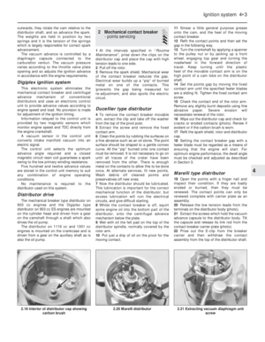 74
74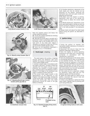 75
75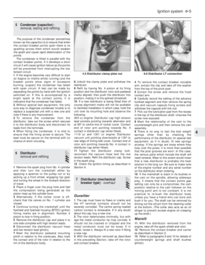 76
76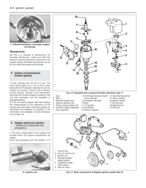 77
77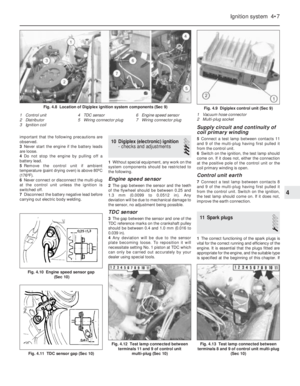 78
78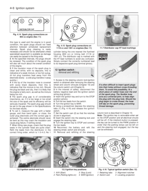 79
79 80
80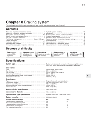 81
81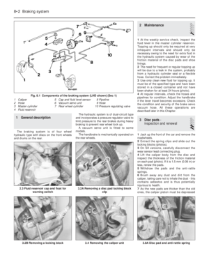 82
82 83
83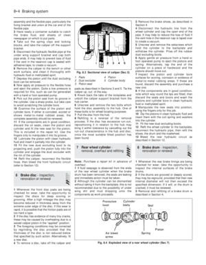 84
84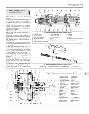 85
85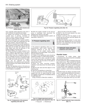 86
86 87
87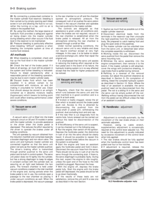 88
88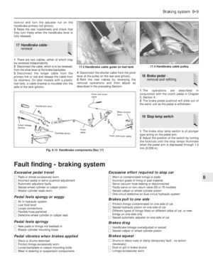 89
89 90
90 91
91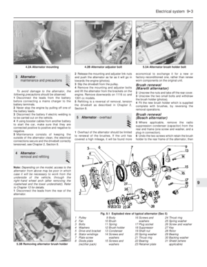 92
92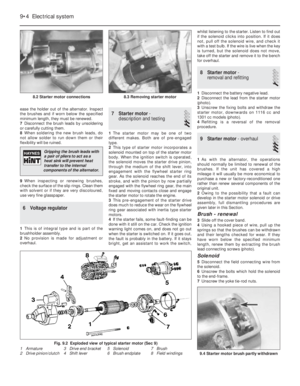 93
93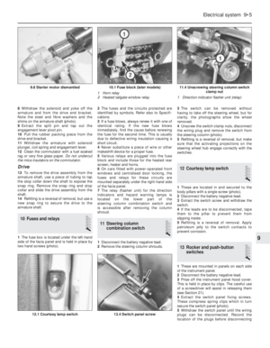 94
94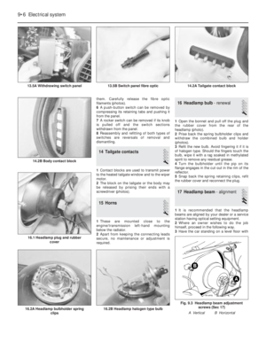 95
95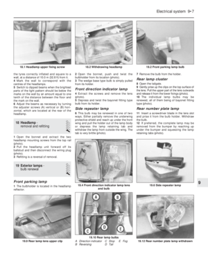 96
96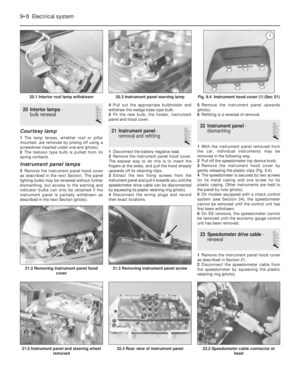 97
97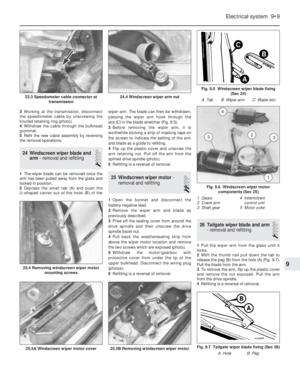 98
98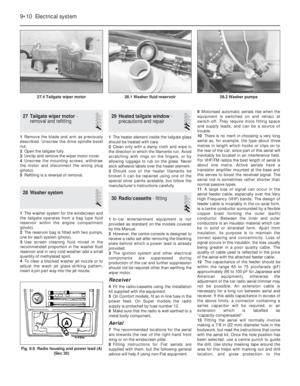 99
99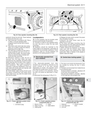 100
100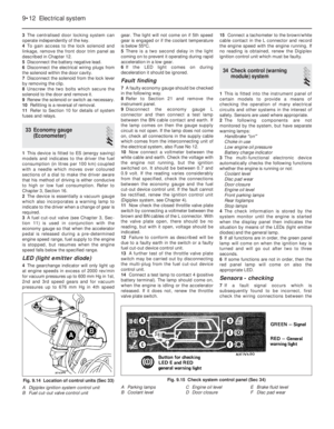 101
101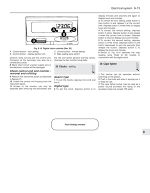 102
102 103
103 104
104 105
105 106
106 107
107 108
108 109
109 110
110 111
111 112
112 113
113 114
114 115
115 116
116 117
117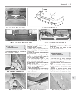 118
118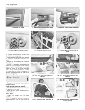 119
119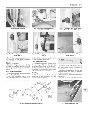 120
120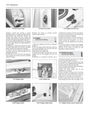 121
121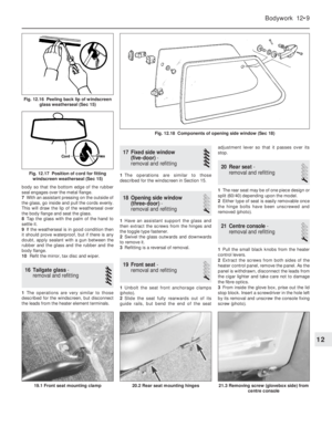 122
122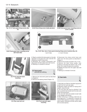 123
123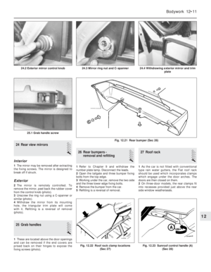 124
124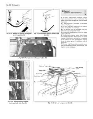 125
125 126
126 127
127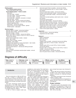 128
128 129
129 130
130 131
131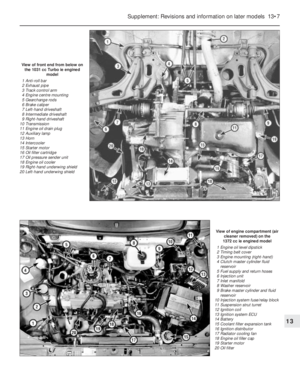 132
132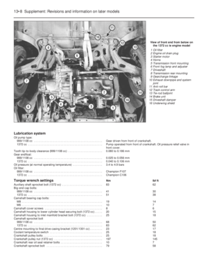 133
133 134
134 135
135 136
136 137
137 138
138 139
139 140
140 141
141 142
142 143
143 144
144 145
145 146
146 147
147 148
148 149
149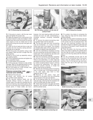 150
150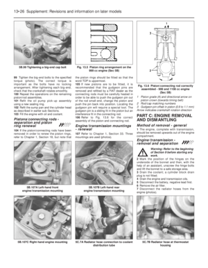 151
151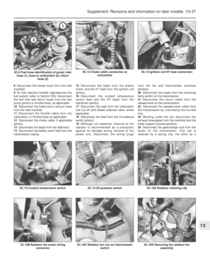 152
152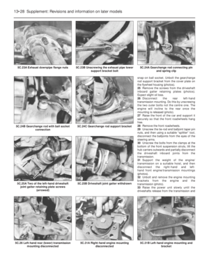 153
153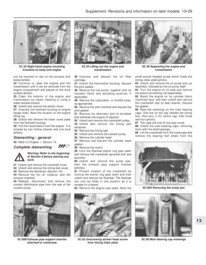 154
154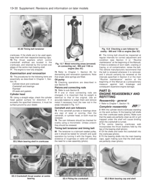 155
155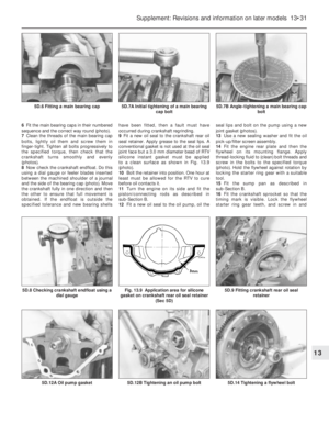 156
156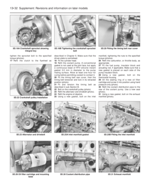 157
157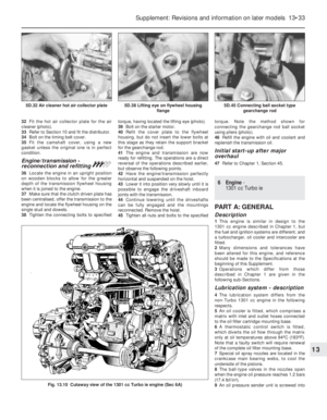 158
158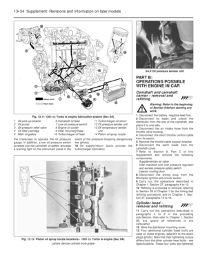 159
159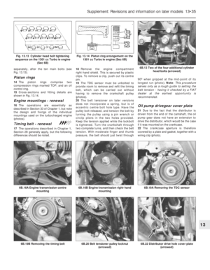 160
160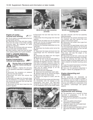 161
161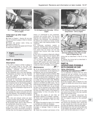 162
162 163
163 164
164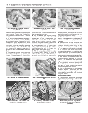 165
165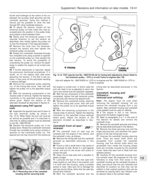 166
166 167
167 168
168 169
169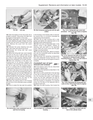 170
170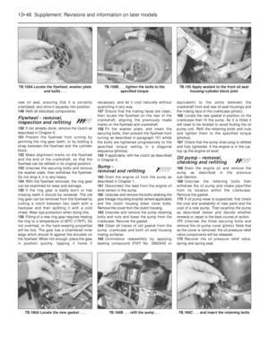 171
171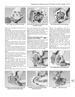 172
172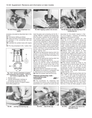 173
173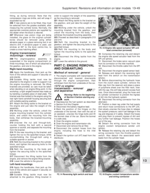 174
174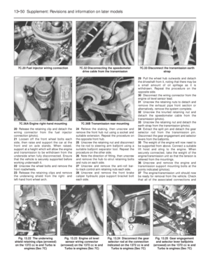 175
175 176
176 177
177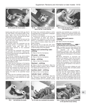 178
178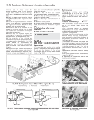 179
179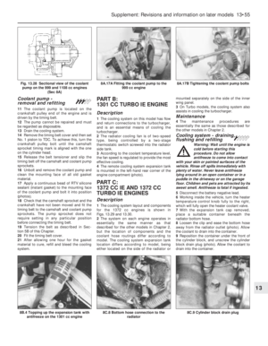 180
180 181
181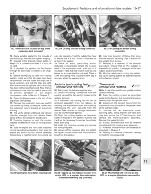 182
182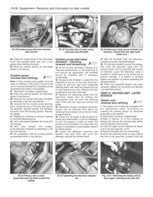 183
183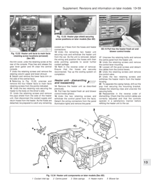 184
184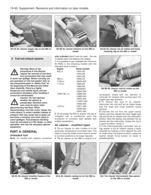 185
185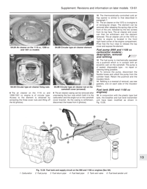 186
186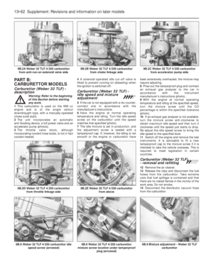 187
187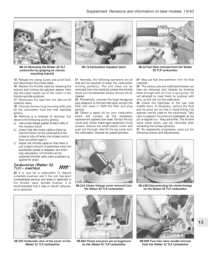 188
188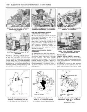 189
189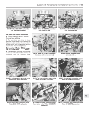 190
190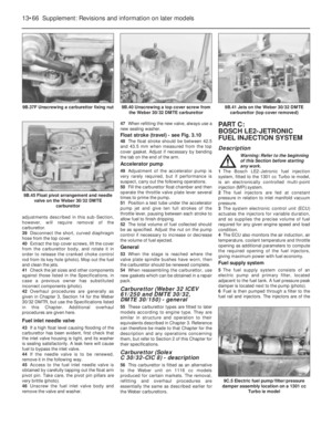 191
191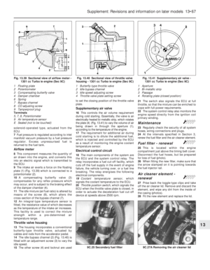 192
192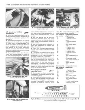 193
193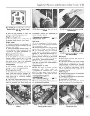 194
194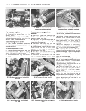 195
195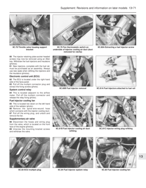 196
196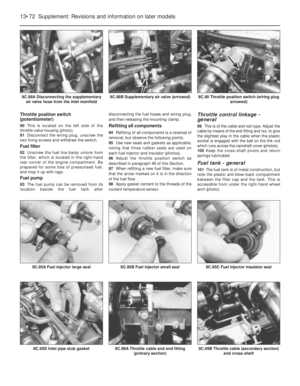 197
197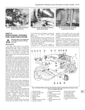 198
198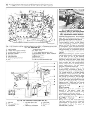 199
199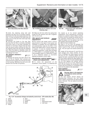 200
200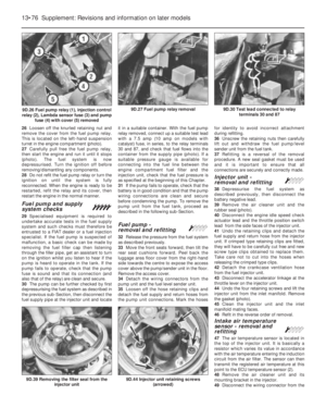 201
201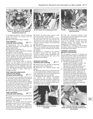 202
202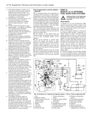 203
203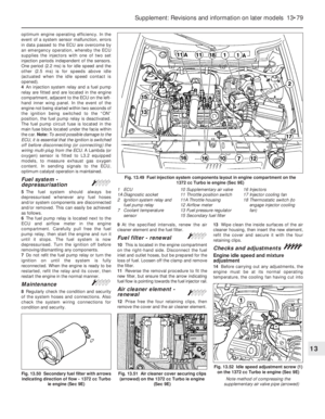 204
204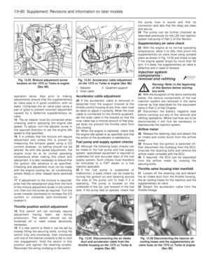 205
205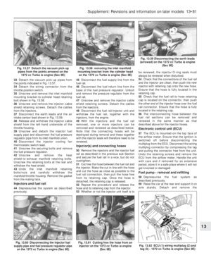 206
206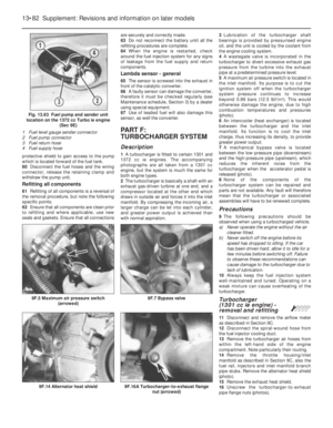 207
207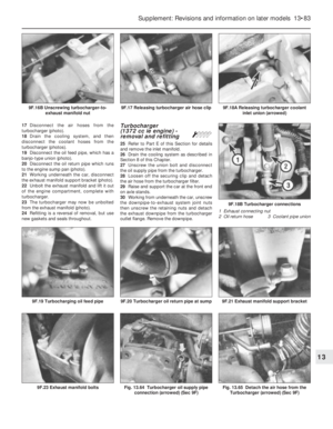 208
208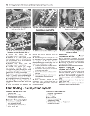 209
209 210
210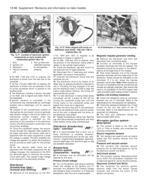 211
211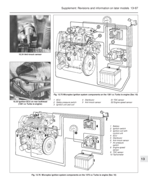 212
212 213
213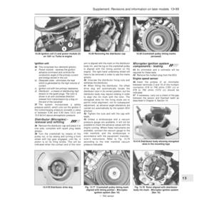 214
214 215
215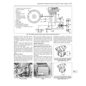 216
216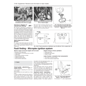 217
217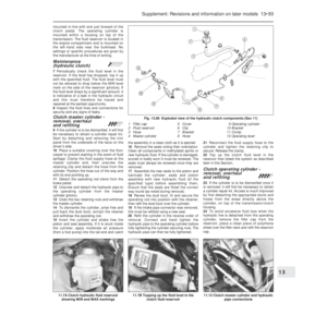 218
218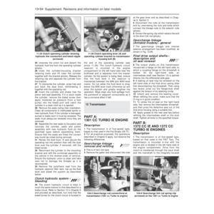 219
219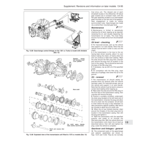 220
220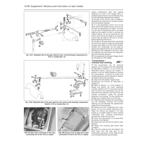 221
221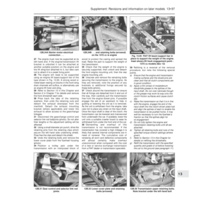 222
222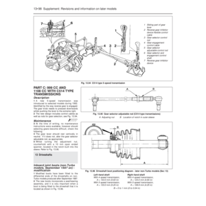 223
223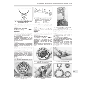 224
224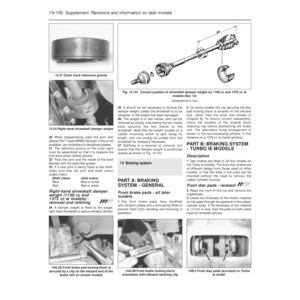 225
225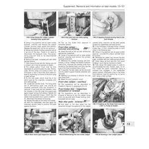 226
226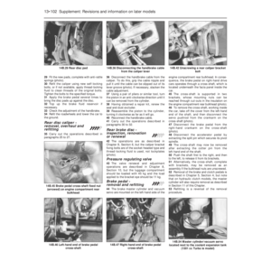 227
227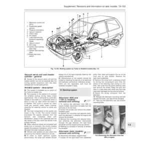 228
228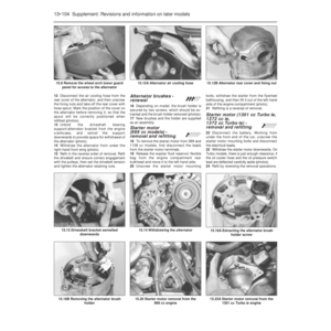 229
229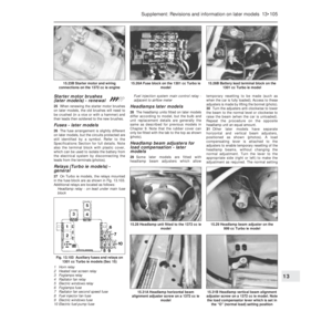 230
230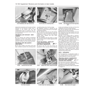 231
231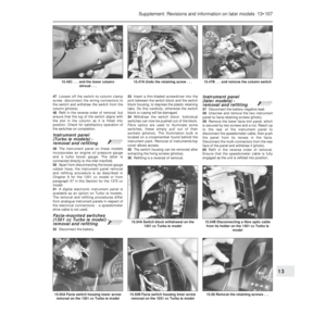 232
232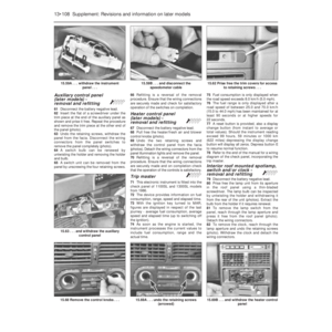 233
233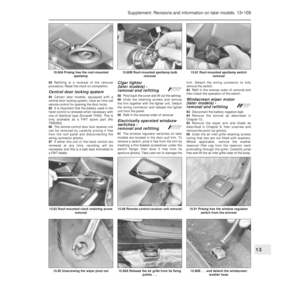 234
234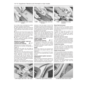 235
235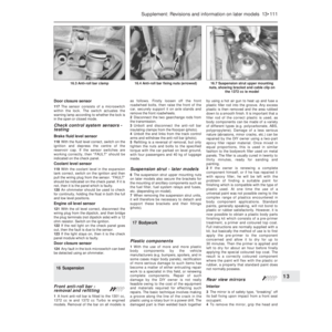 236
236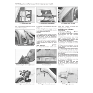 237
237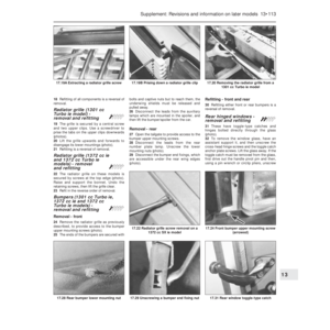 238
238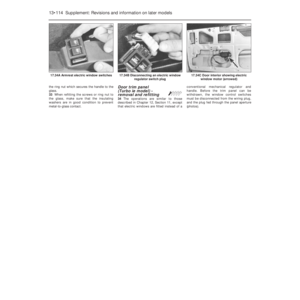 239
239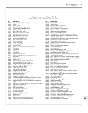 240
240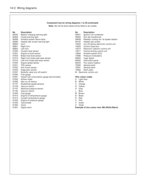 241
241 242
242 243
243 244
244 245
245 246
246 247
247 248
248 249
249 250
250 251
251 252
252 253
253 254
254 255
255 256
256 257
257 258
258 259
259 260
260 261
261 262
262 263
263 264
264 265
265 266
266 267
267 268
268 269
269 270
270 271
271 272
272 273
273 274
274 275
275 276
276 277
277 278
278 279
279 280
280 281
281 282
282 283
283 284
284 285
285 286
286 287
287 288
288 289
289 290
290 291
291 292
292 293
293 294
294 295
295 296
296 297
297 298
298 299
299 300
300 301
301 302
302