1983 FIAT UNO gas tank size
[x] Cancel search: gas tank sizePage 191 of 303

adjustments described in this sub-Section,
however, will require removal of the
carburettor.
39Disconnect the short, curved diaphragm
hose from the top cover.
40Extract the top cover screws, lift the cover
from the carburettor body, and rotate it in
order to release the cranked choke control
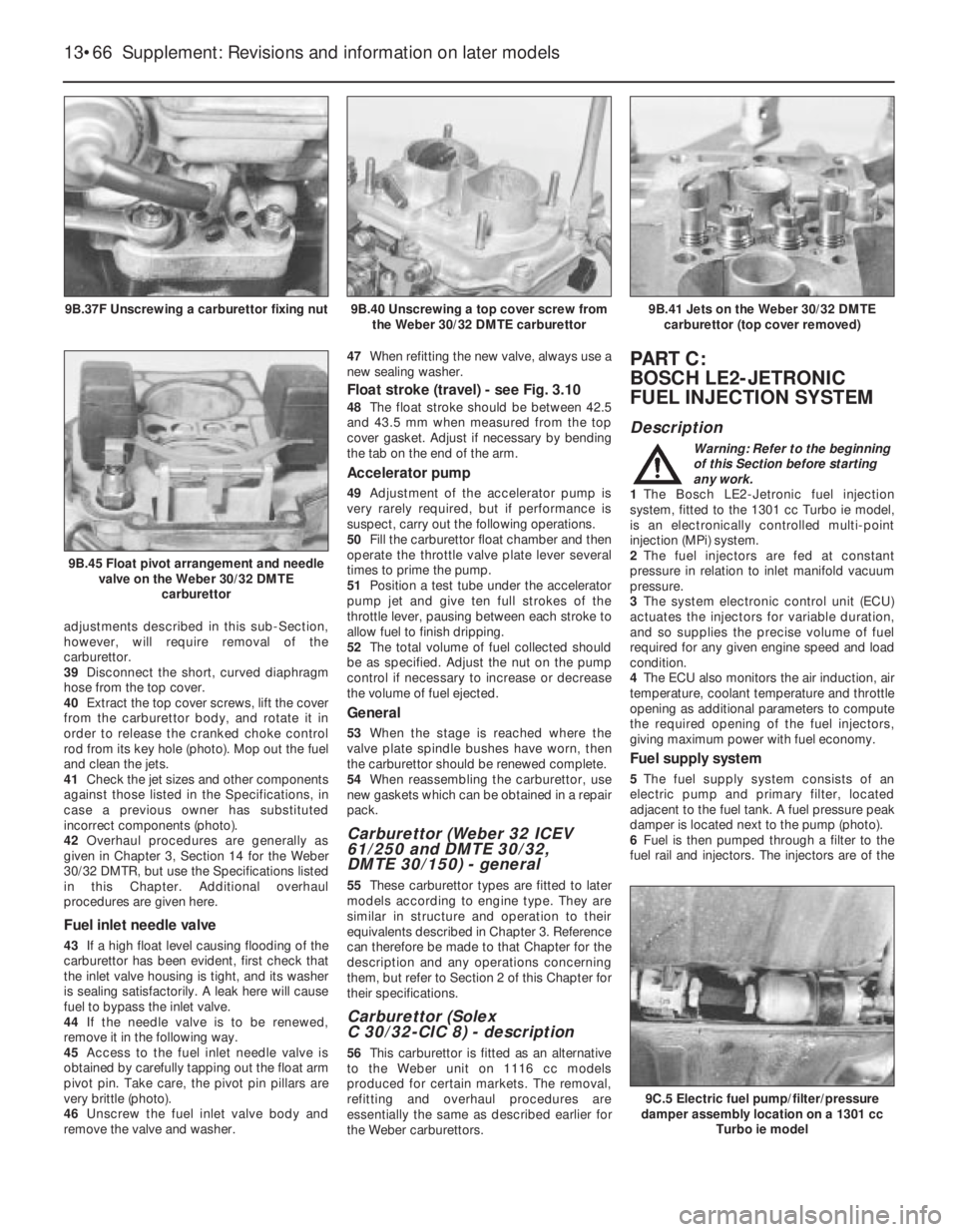
rod from its key hole (photo). Mop out the fuel
and clean the jets.
41Check the jet sizes and other components
against those listed in the Specifications, in
case a previous owner has substituted
incorrect components (photo).
42Overhaul procedures are generally as
given in Chapter 3, Section 14 for the Weber
30/32 DMTR, but use the Specifications listed
in this Chapter. Additional overhaul
procedures are given here.
Fuel inlet needle valve
43If a high float level causing flooding of the
carburettor has been evident, first check that
the inlet valve housing is tight, and its washer
is sealing satisfactorily. A leak here will cause
fuel to bypass the inlet valve.
44If the needle valve is to be renewed,
remove it in the following way.
45Access to the fuel inlet needle valve is
obtained by carefully tapping out the float arm
pivot pin. Take care, the pivot pin pillars are
very brittle (photo).
46Unscrew the fuel inlet valve body and
remove the valve and washer.47When refitting the new valve, always use a
new sealing washer.
Float stroke (travel) - see Fig. 3.10
48The float stroke should be between 42.5
and 43.5 mm when measured from the top
cover gasket. Adjust if necessary by bending
the tab on the end of the arm.
Accelerator pump
49Adjustment of the accelerator pump is
very rarely required, but if performance is
suspect, carry out the following operations.
50Fill the carburettor float chamber and then
operate the throttle valve plate lever several
times to prime the pump.
51Position a test tube under the accelerator
pump jet and give ten full strokes of the
throttle lever, pausing between each stroke to
allow fuel to finish dripping.
52The total volume of fuel collected should
be as specified. Adjust the nut on the pump
control if necessary to increase or decrease
the volume of fuel ejected.
General
53When the stage is reached where the
valve plate spindle bushes have worn, then
the carburettor should be renewed complete.
54When reassembling the carburettor, use
new gaskets which can be obtained in a repair
pack.
Carburettor (Weber 32 ICEV
61/250 and DMTE 30/32,
DMTE 30/150) - general
55These carburettor types are fitted to later
models according to engine type. They are
similar in structure and operation to their
equivalents described in Chapter 3. Reference
can therefore be made to that Chapter for the
description and any operations concerning
them, but refer to Section 2 of this Chapter for
their specifications.
Carburettor (Solex
C 30/32-CIC 8) - description
56This carburettor is fitted as an alternative
to the Weber unit on 1116 cc models
produced for certain markets. The removal,
refitting and overhaul procedures are
essentially the same as described earlier for
the Weber carburettors.
PART C:
BOSCH LE2-JETRONIC
FUEL INJECTION SYSTEM
Description
Warning: Refer to the beginning
of this Section before starting
any work.
1The Bosch LE2-Jetronic fuel injection
system, fitted to the 1301 cc Turbo ie model,
is an electronically controlled multi-point
injection (MPi) system.
2The fuel injectors are fed at constant
pressure in relation to inlet manifold vacuum
pressure.
3The system electronic control unit (ECU)
actuates the injectors for variable duration,
and so supplies the precise volume of fuel
required for any given engine speed and load
condition.
4The ECU also monitors the air induction, air
temperature, coolant temperature and throttle
opening as additional parameters to compute
the required opening of the fuel injectors,
giving maximum power with fuel economy.
Fuel supply system
5The fuel supply system consists of an
electric pump and primary filter, located
adjacent to the fuel tank. A fuel pressure peak
damper is located next to the pump (photo).
6Fuel is then pumped through a filter to the
fuel rail and injectors. The injectors are of the
13•66 Supplement: Revisions and information on later models
9C.5 Electric fuel pump/filter/pressure
damper assembly location on a 1301 cc
Turbo ie model
9B.41 Jets on the Weber 30/32 DMTE
carburettor (top cover removed)
9B.45 Float pivot arrangement and needle
valve on the Weber 30/32 DMTE
carburettor
9B.40 Unscrewing a top cover screw from
the Weber 30/32 DMTE carburettor9B.37F Unscrewing a carburettor fixing nut
Page 287 of 303

REF•4MOT Test Checks
MExamine the handbrake mechanism,
checking for frayed or broken cables,
excessive corrosion, or wear or insecurity of
the linkage. Check that the mechanism works
on each relevant wheel, and releases fully,
without binding.
MIt is not possible to test brake efficiency
without special equipment, but a road test can
be carried out later to check that the vehicle
pulls up in a straight line.
Fuel and exhaust systems
MInspect the fuel tank (including the filler
cap), fuel pipes, hoses and unions. All
components must be secure and free from
leaks.
MExamine the exhaust system over its entire
length, checking for any damaged, broken or
missing mountings, security of the retaining
clamps and rust or corrosion.
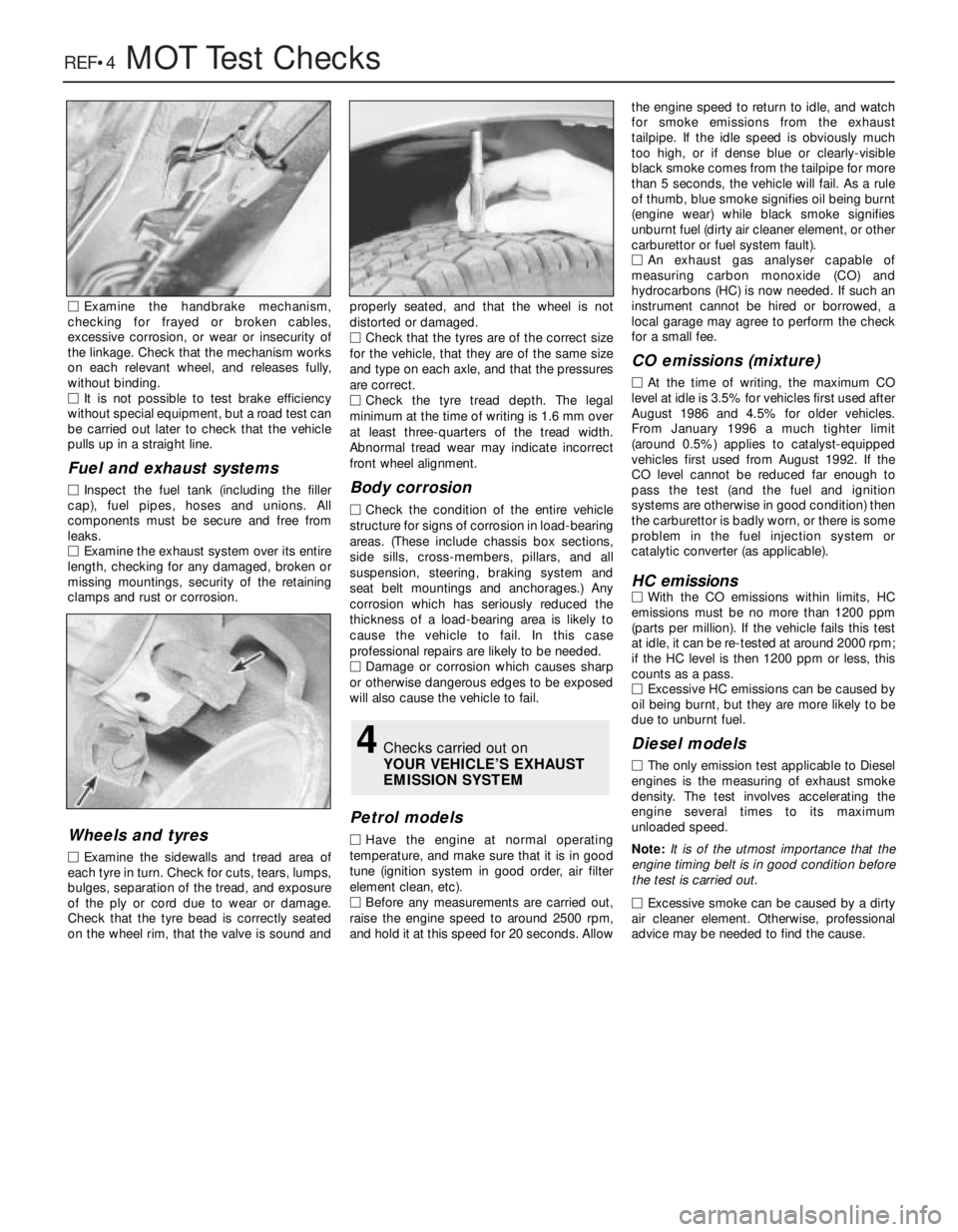
Wheels and tyres
MExamine the sidewalls and tread area of
each tyre in turn. Check for cuts, tears, lumps,
bulges, separation of the tread, and exposure
of the ply or cord due to wear or damage.
Check that the tyre bead is correctly seated
on the wheel rim, that the valve is sound andproperly seated, and that the wheel is not
distorted or damaged.
MCheck that the tyres are of the correct size
for the vehicle, that they are of the same size
and type on each axle, and that the pressures
are correct.
MCheck the tyre tread depth. The legal
minimum at the time of writing is 1.6 mm over
at least three-quarters of the tread width.
Abnormal tread wear may indicate incorrect
front wheel alignment.
Body corrosion
MCheck the condition of the entire vehicle
structure for signs of corrosion in load-bearing
areas. (These include chassis box sections,
side sills, cross-members, pillars, and all
suspension, steering, braking system and
seat belt mountings and anchorages.) Any
corrosion which has seriously reduced the
thickness of a load-bearing area is likely to
cause the vehicle to fail. In this case
professional repairs are likely to be needed.
MDamage or corrosion which causes sharp
or otherwise dangerous edges to be exposed
will also cause the vehicle to fail.
Petrol models
MHave the engine at normal operating
temperature, and make sure that it is in good
tune (ignition system in good order, air filter
element clean, etc).
MBefore any measurements are carried out,
raise the engine speed to around 2500 rpm,
and hold it at this speed for 20 seconds. Allowthe engine speed to return to idle, and watch
for smoke emissions from the exhaust
tailpipe. If the idle speed is obviously much
too high, or if dense blue or clearly-visible
black smoke comes from the tailpipe for more
than 5 seconds, the vehicle will fail. As a rule
of thumb, blue smoke signifies oil being burnt
(engine wear) while black smoke signifies
unburnt fuel (dirty air cleaner element, or other
carburettor or fuel system fault).
MAn exhaust gas analyser capable of
measuring carbon monoxide (CO) and
hydrocarbons (HC) is now needed. If such an
instrument cannot be hired or borrowed, a
local garage may agree to perform the check
for a small fee.
CO emissions (mixture)
MAt the time of writing, the maximum CO
level at idle is 3.5% for vehicles first used after
August 1986 and 4.5% for older vehicles.
From January 1996 a much tighter limit
(around 0.5%) applies to catalyst-equipped
vehicles first used from August 1992. If the
CO level cannot be reduced far enough to
pass the test (and the fuel and ignition
systems are otherwise in good condition) then
the carburettor is badly worn, or there is some
problem in the fuel injection system or
catalytic converter (as applicable).
HC emissionsMWith the CO emissions within limits, HC
emissions must be no more than 1200 ppm
(parts per million). If the vehicle fails this test
at idle, it can be re-tested at around 2000 rpm;
if the HC level is then 1200 ppm or less, this
counts as a pass.
MExcessive HC emissions can be caused by
oil being burnt, but they are more likely to be
due to unburnt fuel.
Diesel models
MThe only emission test applicable to Diesel
engines is the measuring of exhaust smoke
density. The test involves accelerating the
engine several times to its maximum
unloaded speed.
Note: It is of the utmost importance that the
engine timing belt is in good condition before
the test is carried out.
M
Excessive smoke can be caused by a dirty
air cleaner element. Otherwise, professional
advice may be needed to find the cause.
4Checks carried out on
YOUR VEHICLE’S EXHAUST
EMISSION SYSTEM