1983 FIAT UNO washer fluid
[x] Cancel search: washer fluidPage 10 of 303

0•10Routine maintenance
Maintenance is essential for ensuring safety and desirable for the
purpose of getting the best in terms of performance and economy
from the car. Over the years the need for periodic lubrication has been
greatly reduced if not totally eliminated. This has unfortunately tended
to lead some owners to think that because no such action is required
the items either no longer exist or will last forever. This is certainly not
the case; it is essential to carry out regular visual examinations as
comprehensively as possible in order to spot any possible defects at
an early stage before they develop into major and expensive repairs.
For information applicable to later models, see Supplement.
Every 250 miles (400 km), weekly,
or before a long journey
m mCheck engine oil level
m mCheck brake reservoir fluid level
m mCheck tyre pressures
m mCheck operation of all lights and horn
m mTop up washer fluid reservoirs, adding a screen
wash, and check operation of washers and wipers
m mCheck coolant level
m mCheck battery electrolyte level
Every 6000 miles (10 000 km)
or six months, whichever comes first
m mRenew engine oil and filter (Chapter 1, Section 2)
m mCheck drivebelt tension (Chapter 2, Section 8)
m mCheck carburettor idle speed and mixture
adjustments (Chapter 3)
m mCheck contact points and dwell angle (mechanical
breaker distributors) (Chapter 4, Section 3)
m mCheck tyre tread wear (Chapter 7, Section 7)
m mCheck disc pads for wear (Chapter 8, Section 3)
Every 36 000 miles (60 000 km)
or three years, whichever comes first
m mRenew the timing belt - 1116 and 1299/1301 cc
(Chapter 1, Section 28)
m mCheck exhaust system for corrosion (Chapter 3,
Section 19)
m mRenew contact breaker points and adjust dwell
angle (mechanical breaker distributors) (Chapter 4,
Section 3)
m mCheck and adjust ignition timing (Chapter 4,
Section 4)
m mRenew spark plugs (Chapter 4, Section 11)
m mCheck clutch adjustment (Chapter 5, Section 2)
m mCheck transmission oil level (Chapter 6, Section 2)
m mCheck driveshaft and steering rack gaiters for splits
(Chapters 7 and 10)
m mCheck rear brake shoe linings for wear (Chapter 8,
Section 4)
m mCheck handbrake travel (Chapter 8, Section 16)
m mCheck headlamp beam alignment (Chapter 9,
Section 17)
m mCheck balljoints for wear (Chapter 10, Section 2)
m mCheck front wheel alignment (Chapter 10, Section 8)
m mCheck suspension bushes for wear (Chapter 11,
Section 2)
m mCheck seat belts for fraying (Chapter 12, Section 23)
m mLubricate controls, hinges and locks
Every 24 000 miles (40 000 km)
or two years, whichever comes first
m mRenew coolant anti-freeze mixture (Chapter 2,
Section 3)
m mRenew transmission oil (Chapter 6, Section 2)
m mRenew brake hydraulic fluid (Chapter 8, Section 12)
m mCheck for underbody corrosion and clean out door
and sill drain holes (Chapter 12, Section 2)
Every 12 000 miles (20 000 km) or
12 months, whichever comes first
m mCheck and adjust valve clearances (Chapter 1,
Sections 5 and 26)
m mRenew air cleaner element (Chapter 3, Section 2)
Page 11 of 303
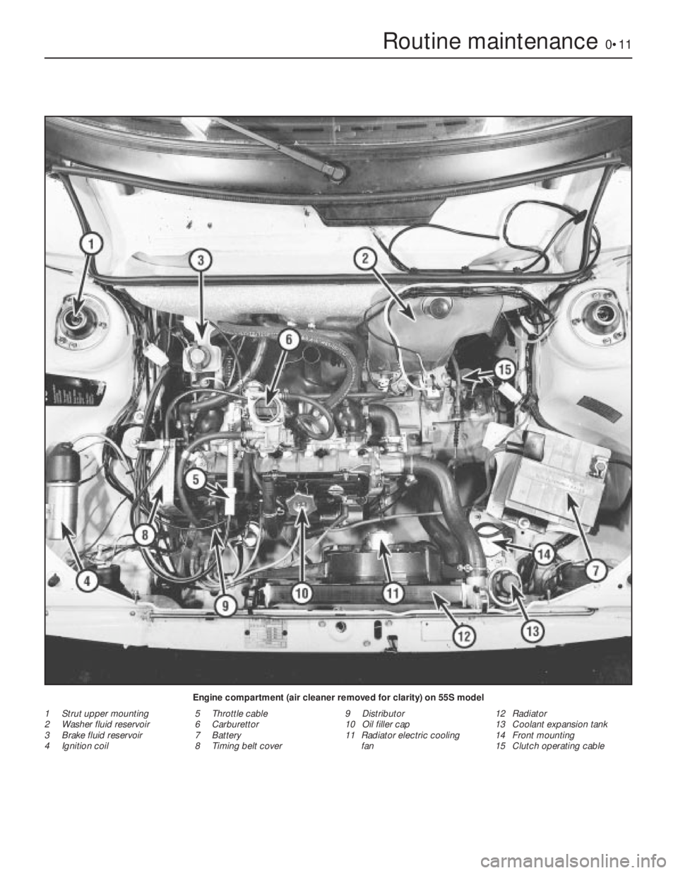
Routine maintenance0•11
Engine compartment (air cleaner removed for clarity) on 55S model
1 Strut upper mounting
2 Washer fluid reservoir
3 Brake fluid reservoir
4 Ignition coil5 Throttle cable
6 Carburettor
7 Battery
8 Timing belt cover9 Distributor
10 Oil filler cap
11 Radiator electric cooling
fan12 Radiator
13 Coolant expansion tank
14 Front mounting
15 Clutch operating cable
Page 84 of 303
assembly and the flexible pipe, particularly the
fixing bracket and union at the car end of the
flexible pipe.
3Have ready a container suitable to catch
the brake fluid, and sheets of clean
newspaper on which to put parts.
4Take out the spring clips and locking
blocks, and take the caliper off the support
bracket.
5Disconnect the hydraulic flexible pipe at the
under wing support bracket and cap both
pipe ends. It may help to prevent loss of fluid
if the vent in the reservoir cap is sealed with
adhesive tape, to create a vacuum.
6Remove the caliper to the bench or other
work surface, and clean it thoroughly with
hydraulic fluid or methylated spirit.
7Depress the piston until the dust excluding
boot can be removed.
8Now apply air pressure to the flexible hose
and eject the piston. Quite a low pressure is
required for this, such as can be generated
with a hand or foot operated pump.
9Pick out the piston seal from its groove in
the cylinder. Use a sharp probe, but take care
to avoid scratching the cylinder bore.
10Examine the surface of the piston and
cylinder bore. If either is corroded, scored or
shows metal-to-metal rubbed areas, the
complete assembly should be renewed.
11If the components are in good condition,
discard the oil seals, clean the piston and
cylinder and fit the new seal for the piston.
This is included in the repair kit. Use the
fingers only to manipulate it into its groove.
12Lubricate the piston with clean hydraulic
fluid and insert it partially into the cylinder.
13Fit the new dust excluding boot to its
projecting end, push the piston fully into the
cylinder and engage the dust excluder with
the rim of the cylinder.
14Refit the caliper, reconnect the flexible
hose, then bleed the front hydraulic circuit
(refer to Section 12).
6 Brake disc- inspection,
renovation or renewal
2
1Whenever the front disc pads are being
checked for wear, take the opportunity to
inspect the discs for deep scoring or
grooving. After a high mileage the disc may
become reduced in thickness away from the
extreme outer edge of the disc. lf this wear is
rapid, it is possible that the friction pads are of
too hard a type.
2If the disc has evidence of many tiny cracks,
these may be caused by overheating due to a
seized caliper piston in the “applied” position.
3The foregoing conditions may be corrected
by regrinding the disc provided that the
thickness of the disc is not reduced below
that specified by such action. Alternatively, fit
a new disc.
4To remove a disc, take off the caliper andpads as described in Sections 3 and 5. Tie the
caliper up, out of the way.
5Knock back the tabs of the lockplates and
unbolt the caliper support bracket from the
hub carrier.
6Unscrew and remove the two bolts which
hold the disc assembly to the hub. One of
these bolts is for wheel locating purposes.
7Pull the disc from the hub.
8Refitting is a reversal of the removal
process. If the disc has excessive run-out,
repositioning it in relation to the hub may
bring it within tolerance by cancelling out the
run-out characteristics in the hub and disc,
once the most suitable fitted position has
been found.
7 Rear wheel cylinder-
removal, overhaul and refitting
4
Note: Purchase a repair kit in advance of
overhaul.
1If fluid seepage is observed from the ends
of the rear wheel cylinder when the brake
drum has been removed, the seals are leaking
and immediate action must be taken.
2Although the cylinder can be dismantled
without taking it from the backplate, this is not
recommended due to the possibility of under
wing dirt and mud dropping onto the
components as work proceeds. 3Remove the brake shoes, as described in
Section 4.
4Disconnect the hydraulic line from the
wheel cylinder and cap the open end of the
pipe. lt may help to reduce the loss of fluid if
the vent hole in the reservoir cap is taped over
to create a vacuum.
5Unscrew and remove the setscrews which
hold the cylinder to the backplate and
withdraw the cylinder. Prise off the rubber
dust excluding boots.
6Apply gentle air pressure from a hand or
foot operated pump to eject the pistons and
spring. Alternatively, tap the end of the
cylinder on a piece of hardwood and the
pistons should move out.
7Inspect the piston and cylinder bore
surfaces for scoring, corrosion or evidence of
metal-to-metal rubbing areas. lf these are
found, discard the assembly and purchase a
new one.
8If the components are in good condition,
note which way round the lips are fitted, then
discard the seals and boots and wash the
pistons and cylinder bore in clean hydraulic
fluid or methylated spirit.
9Manipulate the new seals into position,
using the fingers only for this job.
10Dip the pistons in clean hydraulic fluid and
insert them with the coil spring and washers
into the cylinder.
11Fit the new dust excluding boots.
12Refit the wheel cylinder to the backplate,
reconnect the hydraulic pipe, then refit the
shoes, the drum and the roadwheel.
13Bleed the rear hydraulic circuit as
described in Section 12.
8 Brake drum- inspection,
renovation or renewal
2
1Whenever the rear brake linings are being
checked for wear, take the opportunity to
inspect the internal surfaces of the brake
drums.
2If the drums are grooved or deeply scored,
they may be reground, provided that their new
internal diameter will not then exceed the
specified dimension. If it will, or the drum is
cracked, it must be renewed.
3Removal and refitting of a brake drum is
described in Section 4.
8•4 Braking system
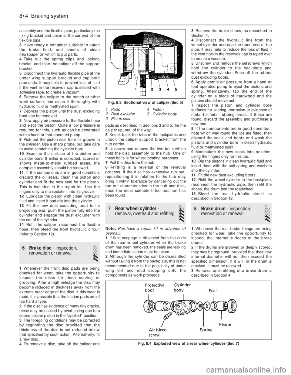
Fig. 8.4 Exploded view of a rear wheel cylinder (Sec 7)
1 Pads
2 Dust excluder
3 Piston seal4 Piston
5 Cylinder body
Fig. 8.3 Sectional view of caliper (Sec 5)
Page 85 of 303
9 Master cylinder- removal,
overhaul and refitting
4
Note: Purchase a repair kit in advance of
overhaul.
1The master cylinder is mounted on the front
face of the brake vacuum servo unit (55 and
70 models) or directly to the bulkhead (45
models).
2Cover the front wings with polythene
sheeting or similar material, in case hydraulic
fluid spills onto the paintwork of the car during
removal of the cylinder.
3Detach the leads from the terminals on the
reservoir cap, then unscrew and remove the
cap and float.
4Unscrew the pipe unions and prise the
pipes carefully away from the master cylinder.
Cap the open ends of the pipes and catch any
fluid leaking from the master cylinder in a
suitable container.
5Unscrew the mounting nuts and withdraw
the master cylinder from the bulkhead or from
the servo unit.
6Clean away all external dirt and tip out the
fluid from the reservoir and cylinder body.
7The fluid reservoirs need not be removed
from the master cylinder but if they are, renew
the rubber sealing collars when refitting.
8Grip the master cylinder in a vice, then
unscrew and remove the end plug. Catch the
coil spring.
9Using a thin rod, apply pressure to the end
of the primary piston then unscrew and
remove the two stop bolts and sealing
washers.
10The internal piston assemblies with seals
and springs can now be pushed out of the
cylinder body. Keep all the components in
Braking system 8•5
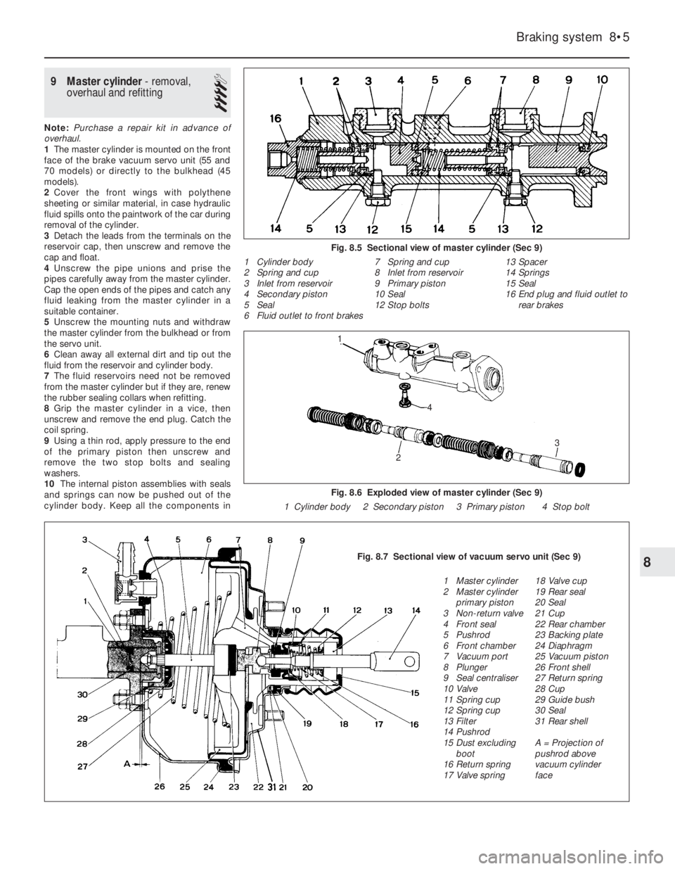
Fig. 8.5 Sectional view of master cylinder (Sec 9)
1 Cylinder body
2 Spring and cup
3 Inlet from reservoir
4 Secondary piston
5 Seal
6 Fluid outlet to front brakes7 Spring and cup
8 Inlet from reservoir
9 Primary piston
10 Seal
12 Stop bolts13 Spacer
14 Springs
15 Seal
16 End plug and fluid outlet to
rear brakes
Fig. 8.6 Exploded view of master cylinder (Sec 9)
1 Cylinder body 2 Secondary piston 3 Primary piston 4 Stop bolt
8Fig. 8.7 Sectional view of vacuum servo unit (Sec 9)
1 Master cylinder
2 Master cylinder
primary piston
3 Non-return valve
4 Front seal
5 Pushrod
6 Front chamber
7 Vacuum port
8 Plunger
9 Seal centraliser
10 Valve
11 Spring cup
12 Spring cup
13 Filter
14 Pushrod
15 Dust excluding
boot
16 Return spring
17 Valve spring18 Valve cup
19 Rear seal
20 Seal
21 Cup
22 Rear chamber
23 Backing plate
24 Diaphragm
25 Vacuum piston
26 Front shell
27 Return spring
28 Cup
29 Guide bush
30 Seal
31 Rear shell
A = Projection of
pushrod above
vacuum cylinder
face
2
3
1
4
Page 99 of 303

27 Tailgate wiper motor-
removal and refitting
1
1Remove the blade and arm as previously
described. Unscrew the drive spindle bezel
nut.
2Open the tailgate fully.
3Unclip and remove the wiper motor cover.
4Unscrew the mounting screws, withdraw
the motor and disconnect the wiring plug
(photo).
5Refitting is a reversal of removal.
28 Washer system
1
1The washer system for the windscreen and
the tailgate operates from a bag type fluid
reservoir within the engine compartment
(photo).
2The reservoir bag is fitted with two pumps,
one for each system (photo).
3Use screen cleaning fluid mixed in the
recommended proportion in the washer fluid
reservoir and in very cold weather add a small
quantity of methylated spirit.
4To clear a blocked washer jet nozzle or to
adjust the wash jet glass-striking pattern,
insert a pin part way into the jet nozzle.
29 Heated tailgate window-
precautions and repair
2
1The heater element inside the tailgate glass
should be treated with care.
2Clean only with a damp cloth and wipe in
the direction in which the filaments run. Avoid
scratching with rings on the fingers, or by
allowing luggage to rub on the glass. Never
stick adhesive labels over the heater element.
3Should one of the heater filaments be
broken it can be repaired using one of the
special silver paints available, but follow the
manufacturer’s instructions carefully.
30 Radio/cassette- fitting
2
1In-car entertainment equipment is not
provided as standard on the models covered
by this Manual.
2However, the centre console is designed to
receive a radio set after removing the blanking
plate behind which a power lead is already
provided.
3The ignition system and other electrical
components are suppressed during
production of the car and further suppression
should not be required other than earthing the
wiper motor.
Receiver
4Fit the radio/cassette using the installation
kit supplied with the equipment.
5On Comfort models, fit an in-line fuse in the
power feed. On Super models the radio
supply is protected by fuse number 12.
6Make sure that the radio is well earthed to a
metal body component.
Aerial
7The recommended locations for the aerial
are towards the rear of the right-hand front
wing or on the windscreen pillar.
8Fitting instructions for Fiat aerials are
supplied with them, but the following general
advice will help if using non-Fiat equipment.9Motorised automatic aerials rise when the
equipment is switched on and retract at
switch-off. They require more fitting space
and supply leads, and can be a source of
trouble.
10There is no merit in choosing a very long
aerial as, for example, the type about three
metres in length which hooks or clips on to
the rear of the car, since part of this aerial will
inevitably be located in an interference field.
For VHF/FM radios the best length of aerial is
about one metre. Active aerials have a
transistor amplifier mounted at the base and
this serves to boost the received signal. The
aerial rod is sometimes rather shorter than
normal passive types.
11A large loss of signal can occur in the
aerial feeder cable, especially over the Very
High Frequency (VHF) bands. The design of
feeder cable is invariably in the co-axial form,
ie a centre conductor surrounded by a flexible
copper braid forming the outer (earth)
conductor. Between the inner and outer
conductors is an insulator material which can
be in solid or stranded form. Apart from
insulation, its purpose is to maintain the
correct spacing and concentricity. Loss of
signal occurs in this insulator, the loss usually
being greater in a poor quality cable. The
quality of cable used is reflected in the price
of the aerial with the attached feeder cable.
12The capacitance of the feeder should be
within the range 65 to 75 picofarads (pF)
approximately (95 to 100 pF for Japanese and
American equipment), otherwise the
adjustment of the car radio aerial trimmer may
not be possible. An extension cable is
necessary for a long run between aerial and
receiver. If this adds capacitance in excess of
the above limits, a connector containing a
series capacitor will be required, or an
extension which is labelled as
“capacity-compensated”.
13Fitting the aerial will normally involve
making a 7/8 in (22 mm) diameter hole in the
bodywork, but read the instructions that come
with the aerial kit. Once the hole position has
been selected, use a centre punch to guide
the drill. Use sticky masking tape around the
area for this helps with marking out and drill
location, and gives protection to the
9•10 Electrical system
Fig. 9.8 Radio housing and power lead (A)
(Sec 30)
28.2 Washer pumps28.1 Washer fluid reservoir27.4 Tailgate wiper motor
Page 130 of 303
Valve timing clearance:
999 cc . . . . . . . . . . . . . . . . . . . . . . . . . . . . . . . . . . . . . . . . . . . . . . . . . 1.0 mm
1108 cc . . . . . . . . . . . . . . . . . . . . . . . . . . . . . . . . . . . . . . . . . . . . . . . . 0.70 mm
1372 cc . . . . . . . . . . . . . . . . . . . . . . . . . . . . . . . . . . . . . . . . . . . . . . . . 0.80 mm
Valve timing:Inlet Exhaust
999 cc:
Opens . . . . . . . . . . . . . . . . . . . . . . . . . . . . . . . . . . . . . . . . . . . . . . . 1º BTDC 29º BBDC
Closes . . . . . . . . . . . . . . . . . . . . . . . . . . . . . . . . . . . . . . . . . . . . . . . 19º ABDC 9º ATDC
1108 cc:
Opens . . . . . . . . . . . . . . . . . . . . . . . . . . . . . . . . . . . . . . . . . . . . . . . 2º BTDC 42º BBDC
Closes . . . . . . . . . . . . . . . . . . . . . . . . . . . . . . . . . . . . . . . . . . . . . . . 19º ABDC 2º ATDC
1116 cc:
Opens . . . . . . . . . . . . . . . . . . . . . . . . . . . . . . . . . . . . . . . . . . . . . . . 7º BTDC 37º BBDC
Closes . . . . . . . . . . . . . . . . . . . . . . . . . . . . . . . . . . . . . . . . . . . . . . . 35º ABDC 5º ATDC
1299/1301 cc:
Opens . . . . . . . . . . . . . . . . . . . . . . . . . . . . . . . . . . . . . . . . . . . . . . . 9º BTDC 39º BBDC
Closes . . . . . . . . . . . . . . . . . . . . . . . . . . . . . . . . . . . . . . . . . . . . . . . 31º ABDC 1º ATDC
1299/1301 cc Turbo ie:
Opens . . . . . . . . . . . . . . . . . . . . . . . . . . . . . . . . . . . . . . . . . . . . . . . 0º TDC 30º BBDC
Closes . . . . . . . . . . . . . . . . . . . . . . . . . . . . . . . . . . . . . . . . . . . . . . . 40º ABDC 10º ATDC
1372 cc ie:
Opens . . . . . . . . . . . . . . . . . . . . . . . . . . . . . . . . . . . . . . . . . . . . . . . 7º BTDC 37º BBDC
Closes . . . . . . . . . . . . . . . . . . . . . . . . . . . . . . . . . . . . . . . . . . . . . . . 35º ABDC 5º ATDC
1372 cc Turbo ie:
Opens . . . . . . . . . . . . . . . . . . . . . . . . . . . . . . . . . . . . . . . . . . . . . . . 14º BTDC 36º BBDC
Closes . . . . . . . . . . . . . . . . . . . . . . . . . . . . . . . . . . . . . . . . . . . . . . . 44º ABDC 6º ATDC
Cam lift:
999 cc . . . . . . . . . . . . . . . . . . . . . . . . . . . . . . . . . . . . . . . . . . . . . . . . . 7.1 mm
1108 cc . . . . . . . . . . . . . . . . . . . . . . . . . . . . . . . . . . . . . . . . . . . . . . . . 8.0 mm
1116 cc . . . . . . . . . . . . . . . . . . . . . . . . . . . . . . . . . . . . . . . . . . . . . . . . 8.8 mm
1299/1301 cc . . . . . . . . . . . . . . . . . . . . . . . . . . . . . . . . . . . . . . . . . . . 8.0 mm
1372 cc ie . . . . . . . . . . . . . . . . . . . . . . . . . . . . . . . . . . . . . . . . . . . . . . 8.8 mm
1372 cc Turbo ie
Inlet valves . . . . . . . . . . . . . . . . . . . . . . . . . . . . . . . . . . . . . . . . . . . 9.5 mm
Exhaust valves . . . . . . . . . . . . . . . . . . . . . . . . . . . . . . . . . . . . . . . . 8.8 mm
Supplement: Revisions and information on later models 13•5
13
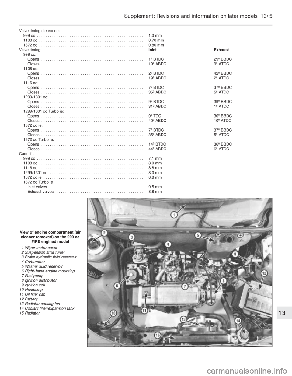
View of engine compartment (air
cleaner removed) on the 999 cc
FIRE engined model
1 Wiper motor cover
2 Suspension strut turret
3 Brake hydraulic fluid reservoir
4 Carburettor
5 Washer fluid reservoir
6 Right-hand engine mounting
7 Fuel pump
8 Ignition distributor
9 Ignition coil
10 Headlamp
11 Oil filler cap
12 Battery
13 Radiator cooling fan
14 Coolant filler/expansion tank
15 Radiator
Page 131 of 303
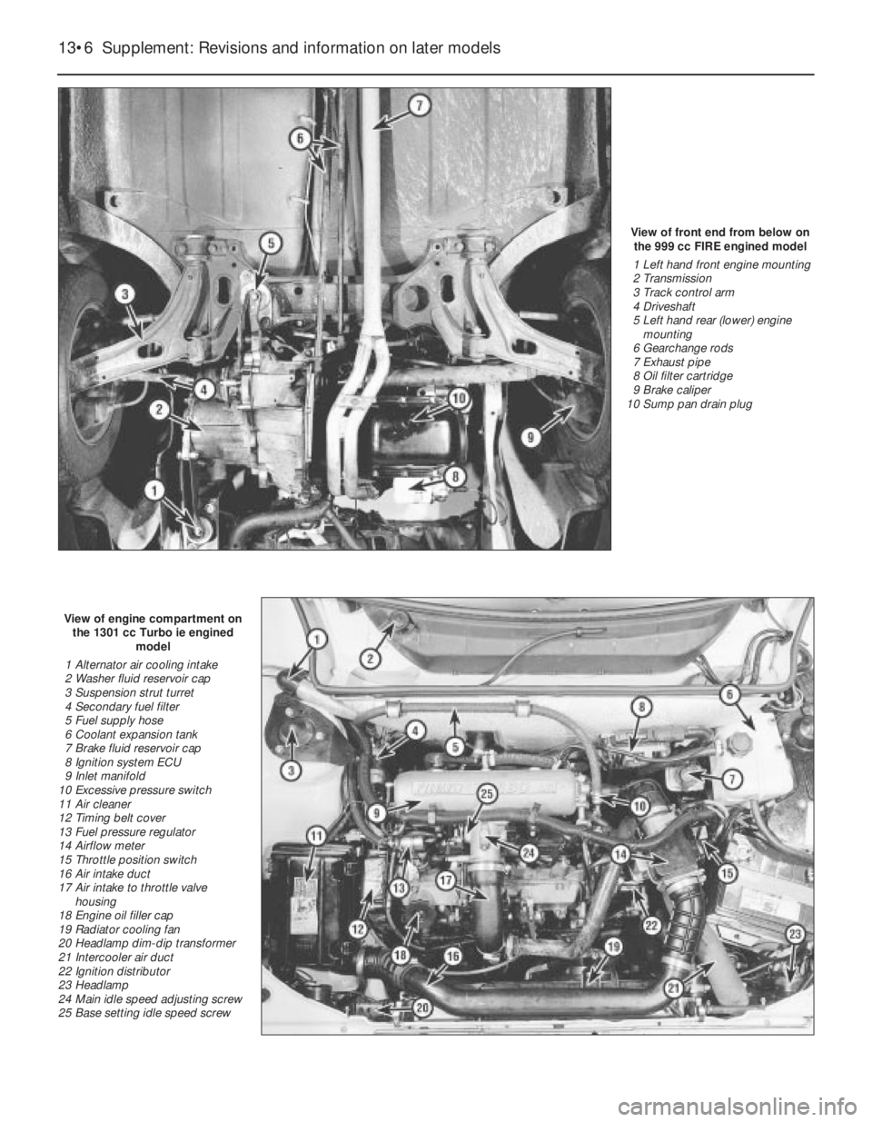
View of front end from below on
the 999 cc FIRE engined model
1 Left hand front engine mounting
2 Transmission
3 Track control arm
4 Driveshaft
5 Left hand rear (lower) engine
mounting
6 Gearchange rods
7 Exhaust pipe
8 Oil filter cartridge
9 Brake caliper
10 Sump pan drain plug
View of engine compartment on
the 1301 cc Turbo ie engined
model
1 Alternator air cooling intake
2 Washer fluid reservoir cap
3 Suspension strut turret
4 Secondary fuel filter
5 Fuel supply hose
6 Coolant expansion tank
7 Brake fluid reservoir cap
8 Ignition system ECU
9 Inlet manifold
10 Excessive pressure switch
11 Air cleaner
12 Timing belt cover
13 Fuel pressure regulator
14 Airflow meter
15 Throttle position switch
16 Air intake duct
17 Air intake to throttle valve
housing
18 Engine oil filler cap
19 Radiator cooling fan
20 Headlamp dim-dip transformer
21 Intercooler air duct
22 Ignition distributor
23 Headlamp
24 Main idle speed adjusting screw
25 Base setting idle speed screw
13•6 Supplement: Revisions and information on later models
Page 132 of 303

Supplement: Revisions and information on later models 13•7
View of engine compartment (air
cleaner removed) on the
1372 cc ie engined model
1 Engine oil level dipstick
2 Timing belt cover
3 Engine mounting (right-hand)
4 Clutch master cylinder fluid
reservoir
5 Fuel supply and return hoses
6 Injection unit
7 Inlet manifold
8 Washer reservoir
9 Brake master cylinder and fluid
reservoir
10 Injection system fuse/relay block
11 Suspension strut turret
12 Ignition coil
13 Ignition system ECU
14 Battery
15 Coolant filter expansion tank
16 Ignition distributor
17 Radiator cooling fan
18 Engine oil filler cap
19 Starter motor
20 Oil filter
View of front end from below on
the 1031 cc Turbo ie engined
model
1 Anti-roll bar
2 Exhaust pipe
3 Track control arm
4 Engine centre mounting
5 Gearchange rods
6 Brake caliper
7 Left-hand driveshaft
8 Intermediate driveshaft
9 Right-hand driveshaft
10 Transmission
11 Engine oil drain plug
12 Auxiliary lamp
13 Horn
14 Intercooler
15 Starter motor
16 Oil filter cartridge
17 Oil pressure sender unit
18 Engine oil cooler
19 Right-hand underwing shield
20 Left-hand underwing shield
13