Page 145 of 303

mounted on the front end of the crankshaft
and driven by it.
11The flexible toothed timing belt drives thecamshaft and the coolant pump from a
sprocket on the front end of the crankshaft.
The belt is tensioned by an
eccentrically-mounted pulley.
12The distributor and the fuel pump
(carburettor models) are driven from the
flywheel end of the camshaft. The fuel pump
on fuel injection models is an integral unit
combined with the fuel gauge sender unit and
immersed in the fuel tank.
PART B:
OPERATIONS POSSIBLE
WITH ENGINE IN CAR
Valve clearances - adjustment
1The operations are similar to those
described in Chapter 1, Section 26, but note
that the special tools referred to have differentpart numbers for the FlRE engine -
1860443000 and 1887001000 (photos).
2Remember that the clearance for inlet and
exhaust valves differs see Specifications at
the beginning of this Supplement.
3Counting from the timing cover end of the
engine, the valve sequence is as follows.
Inlet 2-4-5-7
Exhaust 1-3-6-8
Timing belt - renewal #
4Remove the air cleaner.
5Slacken and remove the alternator
drivebelt, then remove the spark plugs.
6Unbolt and remove the timing belt cover.
Note the bolt located at the bottom of the
cover, this can be easily overlooked (photo).
7Unbolt and remove the crankshaft pulley
(photo).
13•20 Supplement: Revisions and information on later models
5B.7 Unscrewing the crankshaft pulley
bolts5B.6 Timing cover lower fixing bolt
removal5B.1B Using a modified C-spanner and
screwdriver to remove a shim
5B.1A Checking a valve clearance
Fig. 13.3 Longitudinal sectional view of the 999 and 1108 cc
engine (Sec 5A)Fig. 13.4 999 and 1008 cc engine lubrication system (Sec 5A)
Page 146 of 303

8Turn the crankshaft sprocket bolt, or
engage top gear and raise and turn a front
roadwheel, until the camshaft sprocket TDC
timing mark is aligned with the mark on the
cylinder head and the crankshaft sprocket
timing mark is aligned with the mark on the oil
pump cover (photos).
9Release the nut on the timing belt
tensioner, move the pulley away from the belt
and retighten the nut to hold the pulley in the
retracted position (photo).
10Slide the drivebelt from the sprockets.
11When refitting the new belt, make sure
that the sprocket timing marks are still in
alignment and fit the belt so that the arrows
on the belt point in the direction of engine
rotation, and the lines of the belt coincide with
the sprocket marks.
12Engage the timing belt with the crankshaft
sprocket first, then place it around the coolant
pump sprocket and the camshaft sprocket
(photo). Finally slip the belt around the
tensioner pulley.
13Release the tensioner nut and push the
pulley against the belt until the belt is quite
taut. Check that the sprocket timing marks
have not moved out of alignment. If they have,
reset them by moving them over the belt
teeth.
14Still applying force to the pulley, tighten its
nut.
15Turn the crankshaft through two complete
turns in the normal direction of rotation and
check that when the centre of the longest runof the belt is gripped between finger and
thumb it can just be twisted through 90º. If
increased tension is required to achieve this,
release the tensioner nut and prise the pulley
against the timing belt. Note: The above
procedure serves only as a rough guide to
setting the belt tension having it checked by a
FIAT dealer at the earliest opportunity is
recommended.
16Refit the timing belt cover, the crankshaft
pulley, alternator drivebelt, spark plugs and
the air cleaner.
Camshaft -
removal and refitting#
Warning: Refer to the beginning
of Section 9 before starting any
work.
17Remove the air cleaner and the fuel pump(carb. models), as described in Section 9 of
this Supplement.
18Remove the distributor (Section 10).
19Remove the timing belt cover.
20Unbolt and remove the camshaft cover,
having first disconnected the HT lead clip
(photos).
21Turn the crankshaft (by engaging top gear
and raising and turning a front roadwheel)
until No. 4 piston is at TDC. The timing mark
on the camshaft sprocket will be in alignment
with the mark on the cylinder head.
22Pass a rod through one of the holes in the
camshaft sprocket to prevent it rotating and
then unscrew the sprocket fixing bolt. Slip the
sprocket from the camshaft and out of the
loop of the belt (photos).
23Mark the camshaft bearing caps as to
position and then unbolt and remove the
Supplement: Revisions and information on later models 13•21
5B.9 Releasing the timing belt tensioner
nut5B.8B Crankshaft sprocket timing mark
and oil pump cover alignment mark
(arrowed)5B.8A Camshaft sprocket timing mark and
cylinder head timing mark in alignment
5B.22B Camshaft sprocket bolt and
washer5B.22A Unscrewing the camshaft sprocket
bolt
5B.20A Camshaft cover HT lead clip5B.12 Fitting the timing belt
5B.20B Removing the camshaft cover
13
Page 147 of 303
, unscrew the remaining
bolts and take off the bearing caps (photos).
24Lift the camshaft carefully from the
cylinder head, checking t")
lubrication pipe (prise the oil feed stub out
with a screwdriver), unscrew the remaining
bolts and take off the bearing caps (photos).
24Lift the camshaft carefully from the
cylinder head, checking that the valve
clearance shims and cam followers are not
withdrawn by the adhesion of the oil (photo).
25If the shims and cam followers are to be
removed, keep them in their originally fitted
order (photos).
26Refitting is a reversal of removal but use a
new camshaft oil seal and camshaft cover
gasket. Oil the camshaft bearings (photos).
27Make sure that the timing belt is
reconnected and tensioned as described
previously.
28Check the valve clearances.
29Tighten all nuts and bolts to the specified
torque.
Cylinder head -
removal and refitting#
Warning: Refer to the beginning
of Section 9 before starting any
work.
Note: The cylinder head should be removed
cold.
30Drain the cooling system.
31Remove the air cleaner.
32Disconnect the throttle and choke
connections from the carburettor (photo).
33On carburettor models, disconnect the
fuel hoses from the fuel pump and the
carburettor. On fuel injection models,
13•22 Supplement: Revisions and information on later models
5B.26B Camshaft cover gasket5B.26A Camshaft oil seal5B.25B Removing a cam follower (tappet)
with shim
2B.25A Valve clearance shim showing
thickness mark5B.24 Removing the camshaft
5B.23D Camshaft bearing cap showing
short and long positioning dowels for
correct fitting5B.23C Camshaft lubrication pipe
5B.23B Unscrewing the camshaft
bearing/banjo union bolt5B.23A Prising out the camshaft oil feed
pipe stub5B.22C Camshaft sprocket showing
integral key (arrowed)
Page 148 of 303

depressurize the fuel system, before
disconnecting the fuel pipes and removing the
throttle body, as described in Section 9D.
34Disconnect the coolant and vacuum
hoses from the cylinder head and inlet
manifold (photo).
35Disconnect the electrical lead from the
coolant temperature switch, the LT leads from
the distributor and the idle cut-off solenoid
lead.
36Remove the distributor cap, disconnect
the plug leads and place the cap and leads to
one side of the engine compartment.
37Unbolt and remove the timing belt cover.
38Set No. 4 piston to TDC and then release
the timing belt tensioner and slip the belt from
the camshaft and coolant pump sprockets.
39Unbolt and remove the inlet manifold,
complete with carburettor, or throttle body as
applicable.
40Unbolt the exhaust manifold from the
cylinder head and tie it to one side of the
engine compartment; the downpipe bracket
will have to be disconnected.
41Unscrew the cylinder head bolts, a half
turn at a time in the reverse order to that
shown in Fig. 1.30 of Chapter 1. When the
bolts are free, remove them with their
washers.
42Lift the cylinder head from the block. If it is
stuck tight, insert pieces of wood into the
exhaust or inlet ports and use them as levers
to “rock” the head off the block. On no
account drive levers into the gasket joint orattempt to tap the head sideways as it is
located on positioning dowels.
43Remove and discard the cylinder head
gasket and both manifold gaskets.
44The cylinder head can be dismantled after
removing the camshaft and cam followers as
described in the preceding sub-Section.
45Further dismantling and decarbonising are
described in Chapter 1, Section 39. Note that
single valve springs are used.
46If the valves have been ground in, the
valve clearances will require adjusting, as
described previously. This should be done
before the cylinder head is refitted to the
engine.
47Before refitting the assembled cylinder
head, make sure that the head and block
mating surfaces are perfectly clean, and that
the block bolt holes have been cleared of any
oil.
48The camshaft sprocket timing mark must
be aligned with the one on the cylinder head.
49The new gasket should not be removed
from its nylon cover until required for use. Fit
the gasket dry to perfectly clean surfaces.
50Place the gasket on the cylinder block so
that the word ALTO can be read from above
(photos).
51Lower the cylinder head onto the block so
that it locates on the positioning dowels
(photo).
52The cylinder head bolts must have clean
threads, dipped in engine oil and allowed to
drain for thirty minutes. Screw the bolts infinger-tight and then tighten them in the
sequence shown in Fig. 1.30 of Chapter 1,
and in the stages specified (see Specification)
(photos).
53Refit the inlet manifold and carburettor
using a new gasket.
54Reconnect the exhaust manifold using a
new gasket. Tighten all nuts to the specified
torque. Reconnect the exhaust downpipe
bracket.
55Reconnect the timing belt and tension it
as described earlier.
56Refit the timing belt cover and the
distributor cap and camshaft cover.
57Reconnect all hoses, electrical leads and
controls.
58Fit the air cleaner.
59Fill and bleed the cooling system.
Supplement: Revisions and information on later models 13•23
5B.50A Cylinder head gasket5B.34 Inlet manifold coolant hose (A) and
brake servo vacuum hose (B)5B.32 Disconnecting the throttle cable
5B.52B Typical disc for angular tightening
of cylinder head bolts
5B.50B Cylinder head gasket top surface
marking
5B.52A Inserting a cylinder head bolt5B.51 Fitting the cylinder head
13
Page 149 of 303
.
The two lower bolts retain the gearchange rod
supp")
Sump pan -
removal and refitting Á
60Drain the engine oil.
61Unbolt and remove the cover plate from
the lower part of the flywheel housing (photo).
The two lower bolts retain the gearchange rod
support strut.
62Unscrew the sump pan securing screws
and pull the sump pan downwards to remove
it (photo). The joint sealant will require cutting
with a sharp knife to release the pan. Clean
away all old gasket material.
63A bead 3.0 mm in diameter of RTV
silicone instant gasket should be applied to
the sump pan flange and then the pan offered
up. Screw in the fixing screws and tighten to
the specified torque. Note the flange end
fixing screw nuts (photos).64Wait one hour before filling with engine oil.
65Refit the flywheel housing cover plate.Oil pump - removal,
checking and refitting#
66Drain the engine oil and remove the sump
pan as described in the last sub-Section.
Unscrew and remove the oil filter cartridge.
67Remove the timing belt.
68Lock the crankshaft against rotation either
by placing a block of wood between a
crankshaft web and the inside of the
crankcase or by jamming the flywheel starter
ring gear with a suitable tool.
69Unscrew and remove the crankshaft
sprocket bolt and take off the timing belt
sprocket. If it is tight, use two screwdrivers to
lever it off or use a two- or three-legged puller.
70Unbolt and remove the oil pick-up/filter
screen assembly. Note the sealing washer.71Extract the oil pump fixing bolts and
withdraw the pump.
72The oil pump incorporates a pressure
relief valve which can be removed for
examination by depressing the spring plunger
and pulling out the keeper plate (photos).
73If pump wear is suspected, check the
gears in the following way. Extract the fixing
screws and remove the rear cover plate. The
screws are very tight and will probably require
the use of an impact driver to release them
(photo).
74Check the clearance between the outer
gear and the pump housing using feeler
blades, and also the gear endfloat by placing
a straight-edge across the pump body and
checking the gap between the straight-edge
and gear face. If the clearances are outside
the specified tolerance, renew the oil pump
complete (photos).
13•24 Supplement: Revisions and information on later models
5B.74B Checking the oil pump gear
endfloat5B.74A Checking the oil pump gear-to-
housing clearance5B.73 Removing the oil pump rear cover
plate screws
5B.72B Oil pump relief valve components5B.72A Removing the oil pump relief valve
keeper plate5B.63B Sump pan flange end fixing screw
and nut
5B.63A Tightening a sump pan screw5B.62 Removing the sump pan5B.61 Removing the flywheel housing
cover plate
Page 150 of 303

75If the pump is unworn, refit the rear cover
plate and tighten the screws fully.
76Apply air pressure from a tyre pump to the
oil pump oil ducts to clear any sludge or other
material and then prime the pump by pouring
clean engine oil into its intake duct at the
same time turning the oil pump inner gear with
the fingers.
77Lever out the oil seal and drive a new one
squarely into the oil pump casing (photos).
Lubricate the oil seal lips.
78Bolt the pump into position using a new
joint gasket. Note one bolt is longer than the
others (photo).
79Bolt on the oil pick-up assembly using a
new sealing washer.
80Fit the crankshaft sprocket and tighten the
bolt to specified torque.
81Fit and tension the timing belt.
82Fit the sump pan. Screw on a new oil filter
cartridge. Wait for the specified period of time
(one hour) and then fill the engine with oil.
83Run the engine for a few minutes, then
check and top up the oil level.
Pistons/connecting rods -
removal and refitting#
84Remove the sump pan.
85Unbolt and remove the oil pump
pick-up/filter screen assembly.
86The big-end bearing shells can be
renewed without having to remove the
cylinder head if the caps are unbolted and the
piston/connecting rod pushed gently about
one inch up the bore (the crankpin being at its
lowest point). If these shells are worn,however, the main bearing shells will almost
certainly be worn as well, necessitating a
complete overhaul, including crankshaft
removal.
87To remove the piston/connecting rods,
the cylinder head must be removed.
88The big-end caps and their connecting
rods are numbered 1, 2, 3 and 4 from the
timing cover end of the engine. The numbers
are located either side of the rod/cap joint on
the engine oil dipstick tube side (photo).
89Turn the crankshaft as necessary to bring
the first connecting rod big-end crankpin to its
lowest point, then unscrew the cap bolts and
remove the cap and shell bearing.
90Push the connecting rod/piston assembly
up the bore and out of the cylinder block.
There is one reservation; if a wear ridge has
developed at the top of the bores, remove this
by careful scraping before trying to remove
the piston/rod assemblies. The ridge will
otherwise prevent removal, or break the
piston rings during the attempt.
91Remove the remaining piston/connecting
rods in a similar way. If the bearing shells are
to be used again, tape them to their
respective caps or rods.
92Removal of the piston rings and
separation of the piston from the connecting
rod is covered in the next sub-Section.
93Fit the bearing shells into the connecting
rods and caps, ensuring that the recesses into
which the shells seat are clean and dry.
94Check that the piston ring gaps are evenly
spaced at 120º intervals. Liberally oil the rings
and the cylinder bores.95Fit a piston ring clamp to compress the
rings, oiling the rings and the clamp interior
surfaces liberally.
96Insert the first piston/connecting rod into
its cylinder bore. Make sure that the assembly
is the correct one for its particular bore. The
cap and rod matching numbers must be
towards the engine oil dipstick guide tube and
the arrow on the piston crown towards the
timing belt (photo).
97Push the piston into the bore until the
piston ring clamp is against the cylinder block
and then tap the crown of the piston lightly to
push it out of the ring clamp and into the bore
(photo).
98Oil the crankshaft journal and fit the
big-end of the connecting rod to the journal.
Check that the bearing shells are still in
position, then fit the big-end cap and bolts;
check that the cap is the right way round
(photo).
Supplement: Revisions and information on later models 13•25
5B.78 Fitting the oil pump5B.77B Using a socket to fit the new oil
pump oil seal5B.77A Removing the oil pump seal
5B.98 Fitting a big-end bearing cap
5B.88 Connecting rod and cap numbers
5B.97 Fitting a piston/connecting rod5B.96 Piston directional arrow
13
Page 151 of 303
. The correct torque is
important as the bolts have no locking
arrangement. After tightening each big-end,
check that the crankshaft rotates")
99Tighten the big-end bolts to the specified
torque (photo). The correct torque is
important as the bolts have no locking
arrangement. After tightening each big-end,
check that the crankshaft rotates smoothly.
100Repeat the operations on the remaining
piston/rod assemblies.
101Refit the oil pump pick-up assembly
using a new sealing ring.
102Refit the sump pan and the cylinder head
as described in earlier sub-Sections.
103Fill the engine with oil and coolant.
Pistons/connecting rods -
separation and piston
ring renewal
ª
104If the piston/connecting rods have been
removed in order to renew the piston rings,
refer to Chapter 1, Section 18, but note thatthe piston rings should be fitted so that the
word TOP is uppermost.
105If new pistons are to be fitted, it is
recommended that the gudgeon pins are
removed and refitted by a FIAT dealer as the
connecting rods must be carefully heated in
order to be able to push the gudgeon pin out
of the rod small-end, change the piston and
push the pin back into position. Locating the
gudgeon pin will require a special tool. The
gudgeon pin is a sliding fit in the piston but an
interference fit in the connecting rod.
106Refer to Fig. 13.6 for the correct
assembly of the piston and connecting rod.
Engine/transmission mountings
- renewal
107Refer to Chapter 1, Section 33. Three
mountings are used (photos).
PART C: ENGINE REMOVAL
AND DISMANTLING
Method of removal - general
1The engine, complete with transmission,
should be removed upwards out of the engine
compartment.
Engine/transmission -
removal and separation #
Warning: Refer to the beginning
of Section 9 before starting any
work.
2Mark the position of the hinges on the
underside of the bonnet and then, with the
help of an assistant, unscrew the hinge bolts
and lift the bonnet to a safe storage area.
3Drain the coolant; a cylinder block drain
plug is not fitted.
4Drain the engine and transmission oils.
5Disconnect the battery, negative lead first.
6Remove the air filter.
7Disconnect the radiator hoses from the
engine (photos).
13•26 Supplement: Revisions and information on later models
5C.7B Radiator hose at thermostat
housing5C.7A Radiator hose connection to coolant
distribution tube5B.107C Right-hand engine mounting
5B.107B Left-hand rear
engine/transmission mounting5B.107A Left-hand front
engine/transmission mounting
Fig. 13.6 Piston/connecting rod correctly
assembled - 999 and 1108 cc engine
(Sec 5B)
1 Piston grade (A) and directional arrow on
piston crown (towards timing belt)
2 Rod/cap matching numbers
3 Gudgeon pin offset in piston (0.9 to 1.1 mm)
Arrow indicates crankshaft rotation direction
Fig. 13.5 Piston ring arrangement on the
999 cc engine (Sec 5B)5B.99 Tightening a big-end cap bolt
Page 152 of 303
. Disconnect
the fuel inlet and return hoses from the fuel
pump (photo")
8Disconnect the heater hose from the inlet
manifold.
9On fuel injection models, depressurize the
fuel system (refer to Section 9D). Disconnect
the fuel inlet and return hoses from the fuel
pump (photo) or throttle body, as applicable.
10Disconnect the brake servo vacuum hose
from the inlet manifold.
11Disconnect the throttle cable from the
carburettor, or throttle body as applicable.
12Disconnect the choke cable, if applicable
(photo).
13Disconnect the leads from the alternator.
14Disconnect the battery earth lead from the
transmission casing.15Disconnect the leads from the starter
motor and the HT lead from the ignition coil
(photo).
16Disconnect the coolant temperature
switch lead and the HT leads from the
distributor (photo).
17Disconnect the lead from the carburettor
fuel cut-off (anti-diesel) solenoid valve, where
applicable.
18Disconnect the lead from the oil pressure
switch (photo).
19Although not essential, removal of the
radiator is recommended as a precaution
against its damage during removal of the
power unit. Disconnect the wiring plugs from the fan and thermostatic switches
(photos).
20Disconnect the leads from the reversing
lamp switch on the transmission.
21Disconnect the clutch cable from the
release lever on the transmission.
22Disconnect the speedometer cable from
the transmission by unscrewing the knurled
ring.
23Working under the car, disconnect the
exhaust downpipes from the manifold and the
lower support bracket (photos).
24Disconnect the gearchange rods from the
levers on the transmission. One rod is
retained by a spring clip, the other by a
Supplement: Revisions and information on later models 13•27
5C.15 Ignition coil HT lead connection5C.12 Choke cable connection at
carburettor5C.9 Fuel hose identification at pump; inlet
hose (1), hose to carburettor (2), return
hose (3)
5C.19D Removing the radiator/fan
assembly5C.19C Radiator fan cut-out thermostatic
switch5C.19B Radiator fan motor wiring
connector
5C.19A Radiator retaining clip5C.18 Oil pressure switch5C.16 Coolant temperature switch
13
 1
1 2
2 3
3 4
4 5
5 6
6 7
7 8
8 9
9 10
10 11
11 12
12 13
13 14
14 15
15 16
16 17
17 18
18 19
19 20
20 21
21 22
22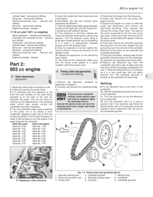 23
23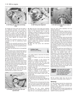 24
24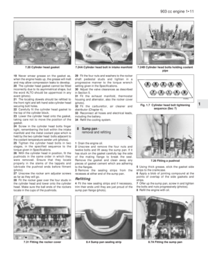 25
25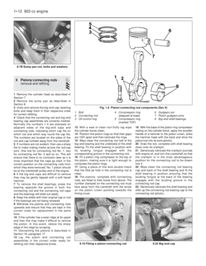 26
26 27
27 28
28 29
29 30
30 31
31 32
32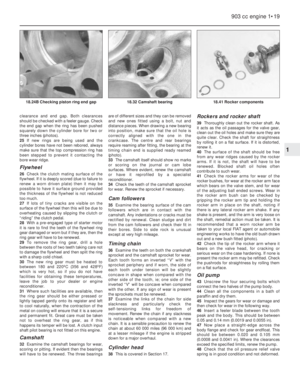 33
33 34
34 35
35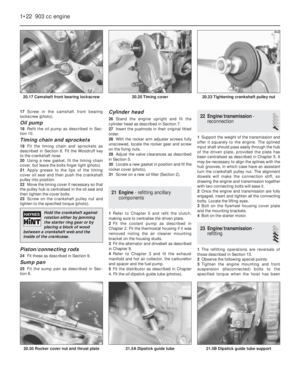 36
36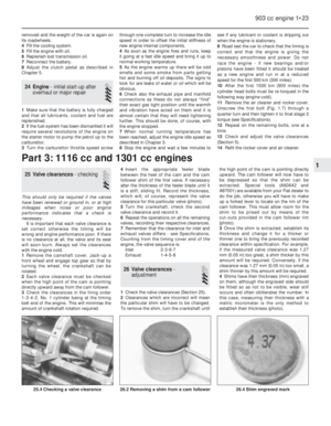 37
37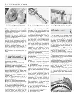 38
38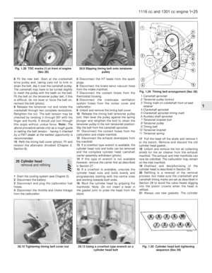 39
39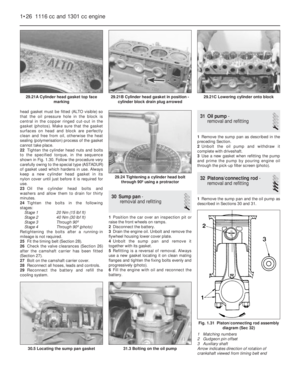 40
40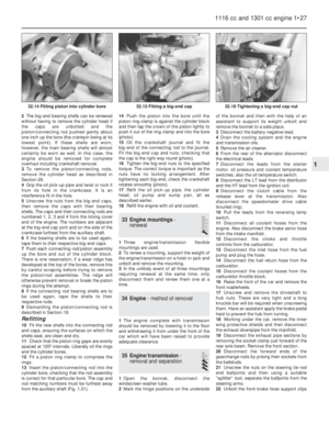 41
41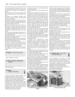 42
42 43
43 44
44 45
45 46
46 47
47 48
48 49
49 50
50 51
51 52
52 53
53 54
54 55
55 56
56 57
57 58
58 59
59 60
60 61
61 62
62 63
63 64
64 65
65 66
66 67
67 68
68 69
69 70
70 71
71 72
72 73
73 74
74 75
75 76
76 77
77 78
78 79
79 80
80 81
81 82
82 83
83 84
84 85
85 86
86 87
87 88
88 89
89 90
90 91
91 92
92 93
93 94
94 95
95 96
96 97
97 98
98 99
99 100
100 101
101 102
102 103
103 104
104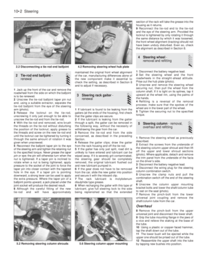 105
105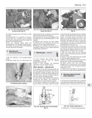 106
106 107
107 108
108 109
109 110
110 111
111 112
112 113
113 114
114 115
115 116
116 117
117 118
118 119
119 120
120 121
121 122
122 123
123 124
124 125
125 126
126 127
127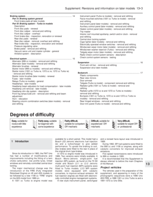 128
128 129
129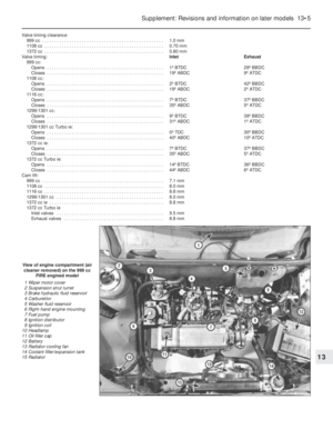 130
130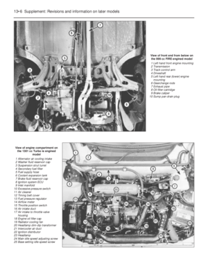 131
131 132
132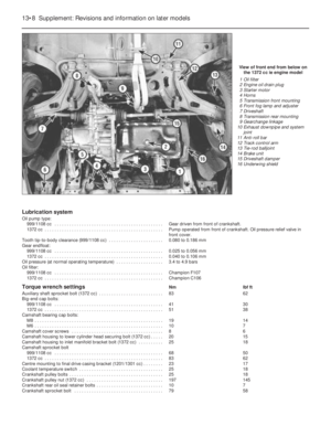 133
133 134
134 135
135 136
136 137
137 138
138 139
139 140
140 141
141 142
142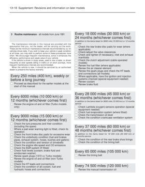 143
143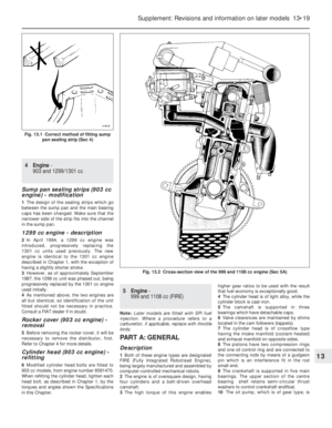 144
144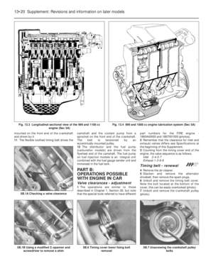 145
145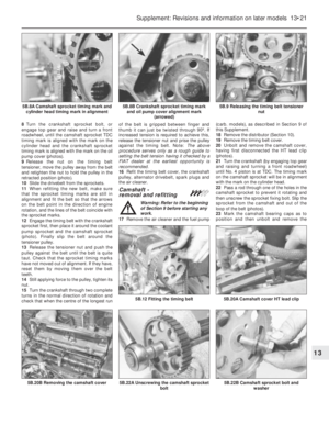 146
146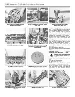 147
147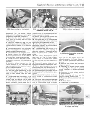 148
148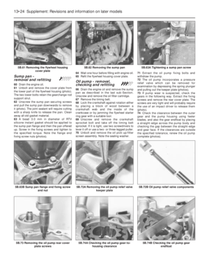 149
149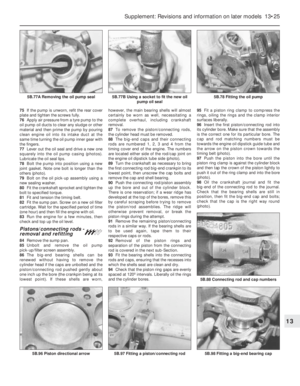 150
150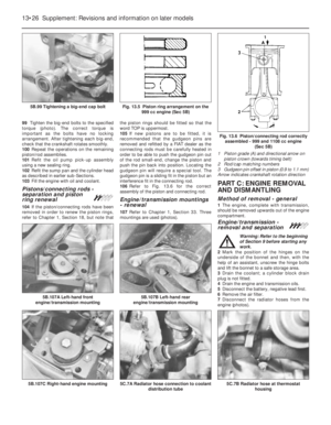 151
151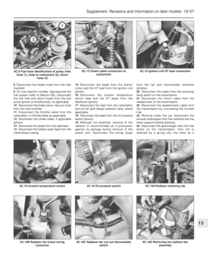 152
152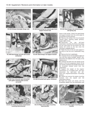 153
153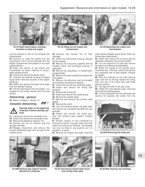 154
154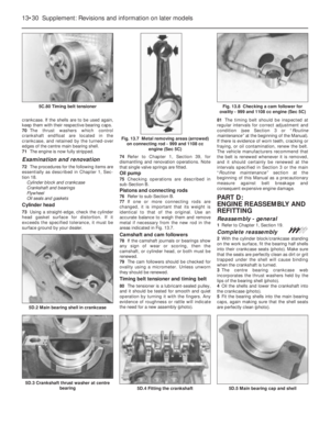 155
155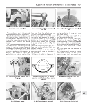 156
156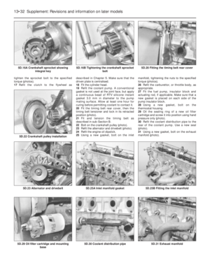 157
157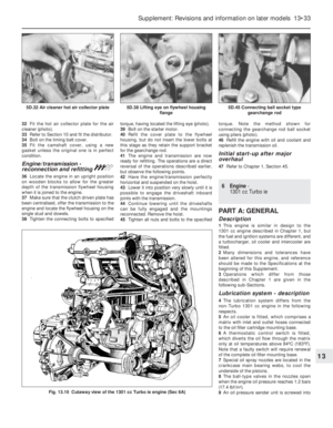 158
158 159
159 160
160 161
161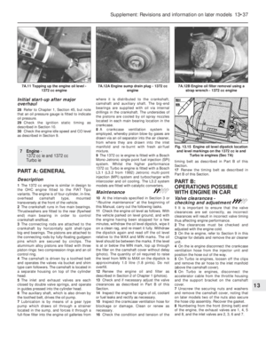 162
162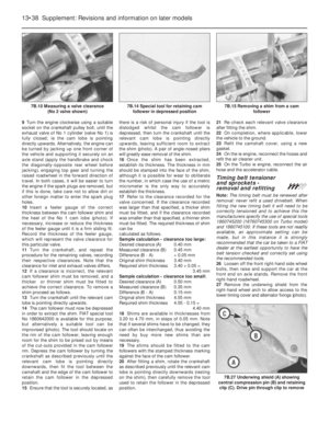 163
163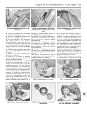 164
164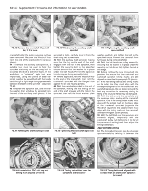 165
165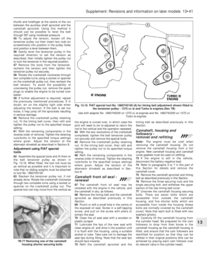 166
166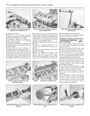 167
167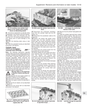 168
168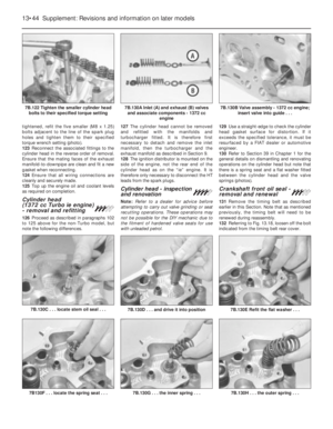 169
169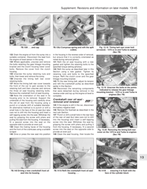 170
170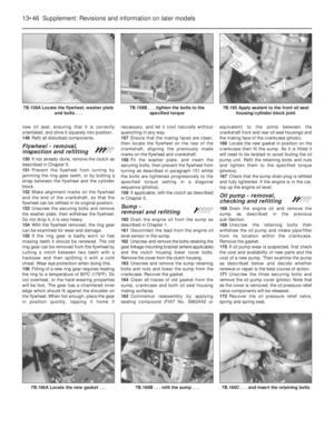 171
171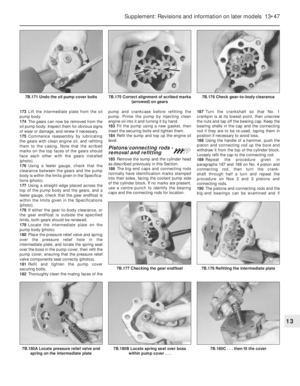 172
172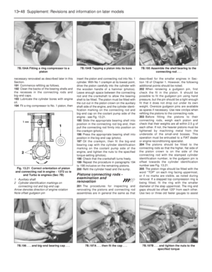 173
173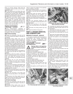 174
174 175
175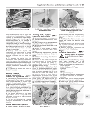 176
176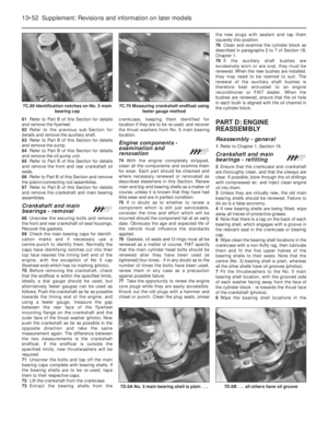 177
177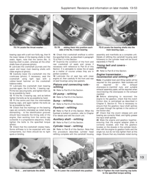 178
178 179
179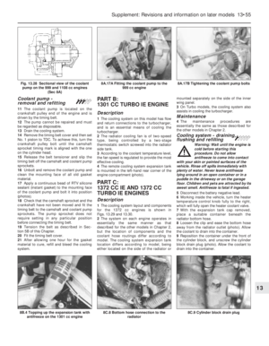 180
180 181
181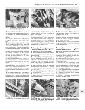 182
182 183
183 184
184 185
185 186
186 187
187 188
188 189
189 190
190 191
191 192
192 193
193 194
194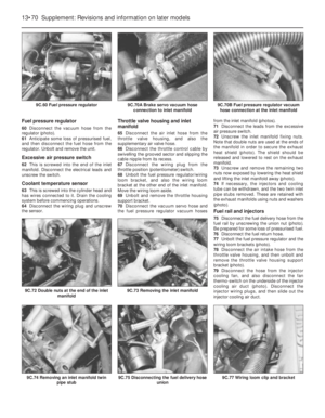 195
195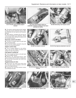 196
196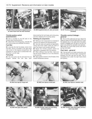 197
197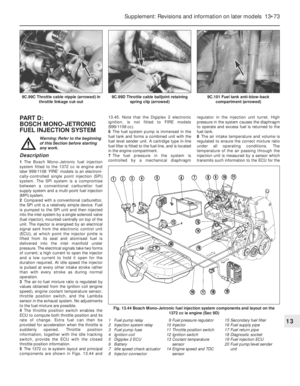 198
198 199
199 200
200 201
201 202
202 203
203 204
204 205
205 206
206 207
207 208
208 209
209 210
210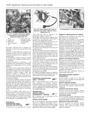 211
211 212
212 213
213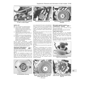 214
214 215
215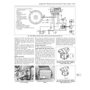 216
216 217
217 218
218 219
219 220
220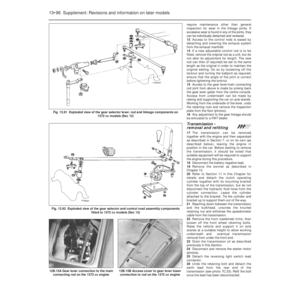 221
221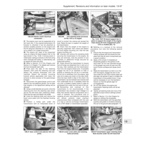 222
222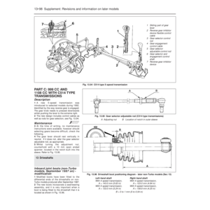 223
223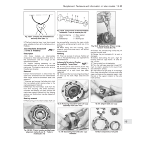 224
224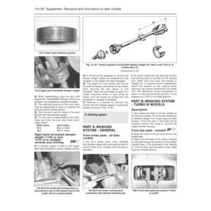 225
225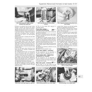 226
226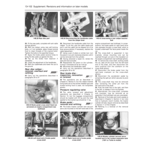 227
227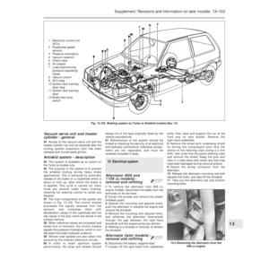 228
228 229
229 230
230 231
231 232
232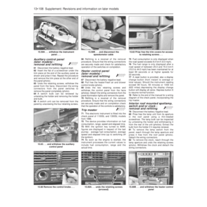 233
233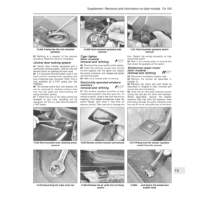 234
234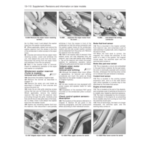 235
235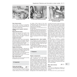 236
236 237
237 238
238 239
239 240
240 241
241 242
242 243
243 244
244 245
245 246
246 247
247 248
248 249
249 250
250 251
251 252
252 253
253 254
254 255
255 256
256 257
257 258
258 259
259 260
260 261
261 262
262 263
263 264
264 265
265 266
266 267
267 268
268 269
269 270
270 271
271 272
272 273
273 274
274 275
275 276
276 277
277 278
278 279
279 280
280 281
281 282
282 283
283 284
284 285
285 286
286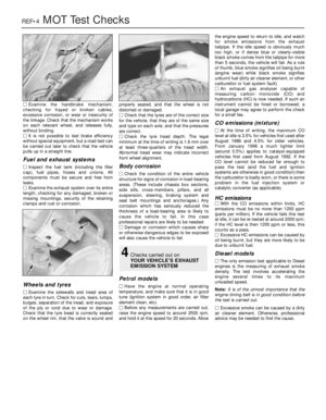 287
287 288
288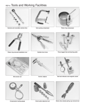 289
289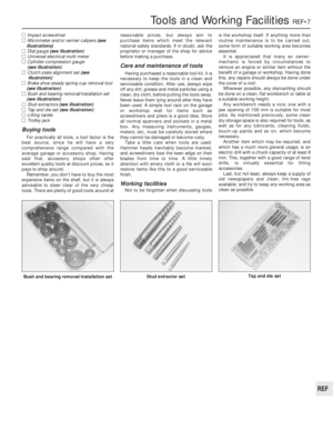 290
290 291
291 292
292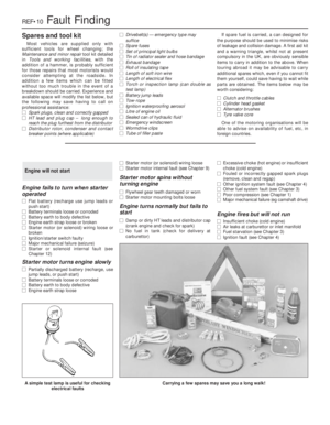 293
293 294
294 295
295 296
296 297
297 298
298 299
299 300
300 301
301 302
302