Page 57 of 303
2The control lever mounting platform can be
removed after extracting its fixing screws.
3The coolant control valve can be removed
after extracting its fixing nuts.
4Unscrew the screws which hold the heater
matrix in the casing and then slide the matrix
from its location. 5If the matrix is leaking, do not attempt a
repair, but obtain a new one. These are
usually obtainable on an exchange basis from
radiator repairers.
6The heater casing can be separated after
prising off the clips and removing the bolts.
The blower motor/fan can then be lifted out. 7Reassembly is a reversal of dismantling, but
set the cables to give complete range of travel
between open and closed positions of the flap
valve or coolant valve concerned.
Cooling and heating systems 2•7
Fig. 2.11 Exploded view of heater (Sec 13)
Fig. 2.12 Heater control components (Sec 13)
2
Page 58 of 303
Fault finding - cooling and heating systems
2•8 Cooling and heating systems
Overheating
m mInsufficient coolant in system
m mPump ineffective due to slack drivebelt
m mRadiator blocked either internally or externally
m mKinked or collapsed hose causing coolant flow restriction
m mThermostat not working properly
m mEngine out of tune
m mIgnition timing retarded or auto advance malfunction
m mCylinder head gasket blown
m mEngine not yet run-in
m mExhaust system partially blocked
m mEngine oil level too low
m mBrakes binding
Engine running too cool
m
mFaulty, incorrect or missing thermostat
Loss of coolant
m
mLoose hose clips
m mHoses perished or leaking
m mRadiator leaking
m mFiller/pressure cap defective
m mBlown cylinder head gasket
m mCracked cylinder block or head
Heater gives insufficient output
m
mEngine overcooled (see above)
m mHeater matrix blocked
m mHeater controls maladjusted or broken
m mHeater control valve jammed or otherwise
defective
Page 59 of 303

3
System type . . . . . . . . . . . . . . . . . . . . . . . . . . . . . . . . . . . . . . . . . . . Rear mounted fuel tank, mechanically-operated fuel pump,
downdraught carburettor
Air cleaner element
903 cc (45) and 1116 cc (55) engine . . . . . . . . . . . . . . . . . . . . . . . . . . . . Champion W121
1116 cc (60) and 1299/1301 cc (70) engines . . . . . . . . . . . . . . . . . . . . . Champion W136
Fuel tank
Capacity . . . . . . . . . . . . . . . . . . . . . . . . . . . . . . . . . . . . . . . . . . . . . . . . . 42.0 litre (9.25 gal)
Octane rating . . . . . . . . . . . . . . . . . . . . . . . . . . . . . . . . . . . . . . . . . . . . . Leaded 97 RON minimum (see Supplement for use of unleaded petrol)
Fuel filter . . . . . . . . . . . . . . . . . . . . . . . . . . . . . . . . . . . . . . . . . . . . . . Champion L101
Carburettor - calibration (dimensions in mm)
Weber 32 ICEV 50/250/1
Application . . . . . . . . . . . . . . . . . . . . . . . . . . . . . . . . . . . . . . . . . . . . . . . 903 cc engine
Venturi . . . . . . . . . . . . . . . . . . . . . . . . . . . . . . . . . . . . . . . . . . . . . . . . . . . 22
Auxiliary venturi . . . . . . . . . . . . . . . . . . . . . . . . . . . . . . . . . . . . . . . . . . . 3.5
Main jet . . . . . . . . . . . . . . . . . . . . . . . . . . . . . . . . . . . . . . . . . . . . . . . . . . 1.12
Air bleed . . . . . . . . . . . . . . . . . . . . . . . . . . . . . . . . . . . . . . . . . . . . . . . . . 1.70
Emulsion tube . . . . . . . . . . . . . . . . . . . . . . . . . . . . . . . . . . . . . . . . . . . . . F89
Idle jet . . . . . . . . . . . . . . . . . . . . . . . . . . . . . . . . . . . . . . . . . . . . . . . . . . . 0.47
Air idle jet . . . . . . . . . . . . . . . . . . . . . . . . . . . . . . . . . . . . . . . . . . . . . . . . 1.60
Pump jet . . . . . . . . . . . . . . . . . . . . . . . . . . . . . . . . . . . . . . . . . . . . . . . . . 0.40
Pump outlet . . . . . . . . . . . . . . . . . . . . . . . . . . . . . . . . . . . . . . . . . . . . . . 0.40
Superfeed jet . . . . . . . . . . . . . . . . . . . . . . . . . . . . . . . . . . . . . . . . . . . . . 0.80
Superfeed mixture jet . . . . . . . . . . . . . . . . . . . . . . . . . . . . . . . . . . . . . . . 2.50
Fuel inlet needle valve . . . . . . . . . . . . . . . . . . . . . . . . . . . . . . . . . . . . . . 1.50
Anti-syphon device . . . . . . . . . . . . . . . . . . . . . . . . . . . . . . . . . . . . . . . . . 1.00
Idle mixture adjustment hole . . . . . . . . . . . . . . . . . . . . . . . . . . . . . . . . . 1.50
Float setting (fuel level) . . . . . . . . . . . . . . . . . . . . . . . . . . . . . . . . . . . . . . 10.5 to 11.0
Float setting (travel/stroke) . . . . . . . . . . . . . . . . . . . . . . . . . . . . . . . . . . . 45.0
Fast idle (throttle valve gap) . . . . . . . . . . . . . . . . . . . . . . . . . . . . . . . . . . 0.75 to 0.80
Accelerator pump delivery (ten strokes) . . . . . . . . . . . . . . . . . . . . . . . . . 4.0 to 5.5 cc
Chapter 3 Fuel system
For modifications, and information applicable to later models, see Supplement at end of manual
Accelerator cable - adjustment and renewal . . . . . . . . . . . . . . . . . . 17
Air cleaner - servicing, removal and refitting . . . . . . . . . . . . . . . . . . . 2
Carburettor - removal and refitting . . . . . . . . . . . . . . . . . . . . . . . . . . 8
Carburettor idle speed and mixture - adjustment . . . . . . . . . . . . . . . 7
Carburettor (Solex C32 DISA 12) - servicing and adjustment . . . . . . 13
Carburettor (Solex C30 - 32 CIC/1) - servicing and adjustment . . . . 15
Carburettor (Solex C32 DISA 11) - servicing and adjustment . . . . . . 10
Carburettor (Weber 30/32 DMTR 90/250) - servicing and
adjustment . . . . . . . . . . . . . . . . . . . . . . . . . . . . . . . . . . . . . . . . . . . 14
Carburettor (Weber 32 ICEV 50/250/1) - servicing and adjustment . . 9
Carburettor (Weber 32 ICEV 51/250) - servicing and adjustment . . . 12Carburettors (Weber 32 ICEE/250 and Solex C32 DISA 14) -
description and adjustment . . . . . . . . . . . . . . . . . . . . . . . . . . . . . . 11
Carburettors - general . . . . . . . . . . . . . . . . . . . . . . . . . . . . . . . . . . . . 6
Choke control cable - removal and refitting . . . . . . . . . . . . . . . . . . . 18
Description and maintenance . . . . . . . . . . . . . . . . . . . . . . . . . . . . . . 1
Economy meter . . . . . . . . . . . . . . . . . . . . . . . . . . . . . . . . . . . . . . . . 16
Fault finding - fuel system . . . . . . . . . . . . . . . . . . . See end of Chapter
Fuel level transmitter - removal and refitting . . . . . . . . . . . . . . . . . . . 4
Fuel pump - removal and refitting . . . . . . . . . . . . . . . . . . . . . . . . . . . 3
Fuel tank - removal and refitting . . . . . . . . . . . . . . . . . . . . . . . . . . . . 5
Manifolds and exhaust system . . . . . . . . . . . . . . . . . . . . . . . . . . . . . 19
3•1
Specifications Contents
Easy,suitable for
novice with little
experienceFairly easy,suitable
for beginner with
some experienceFairly difficult,
suitable for competent
DIY mechanic
Difficult,suitable for
experienced DIY
mechanicVery difficult,
suitable for expert DIY
or professional
Degrees of difficulty
54321
Page 60 of 303

Solex C32 DISA 11
Application . . . . . . . . . . . . . . . . . . . . . . . . . . . . . . . . . . . . . . . . . . . . . . . 903 cc engine
Venturi . . . . . . . . . . . . . . . . . . . . . . . . . . . . . . . . . . . . . . . . . . . . . . . . . . . 23
Auxiliary venturi . . . . . . . . . . . . . . . . . . . . . . . . . . . . . . . . . . . . . . . . . . . 3.4
Main jet . . . . . . . . . . . . . . . . . . . . . . . . . . . . . . . . . . . . . . . . . . . . . . . . . . 1.20
Air bleed jet . . . . . . . . . . . . . . . . . . . . . . . . . . . . . . . . . . . . . . . . . . . . . . . 1.35
Emulsion tube . . . . . . . . . . . . . . . . . . . . . . . . . . . . . . . . . . . . . . . . . . . . . B03
Idle jet . . . . . . . . . . . . . . . . . . . . . . . . . . . . . . . . . . . . . . . . . . . . . . . . . . . 0.525
Air idle jet . . . . . . . . . . . . . . . . . . . . . . . . . . . . . . . . . . . . . . . . . . . . . . . . 1.20
Pump jet . . . . . . . . . . . . . . . . . . . . . . . . . . . . . . . . . . . . . . . . . . . . . . . . . 0.50
Pump outlet . . . . . . . . . . . . . . . . . . . . . . . . . . . . . . . . . . . . . . . . . . . . . . 0.45
Fuel inlet needle valve . . . . . . . . . . . . . . . . . . . . . . . . . . . . . . . . . . . . . . 1.60
Anti-syphon device . . . . . . . . . . . . . . . . . . . . . . . . . . . . . . . . . . . . . . . . . 2.0
Idle mixture adjustment hole . . . . . . . . . . . . . . . . . . . . . . . . . . . . . . . . . 1.10
Float setting (fuel level) . . . . . . . . . . . . . . . . . . . . . . . . . . . . . . . . . . . . . . 2.0 to 3.0
Fast idle (throttle valve gap) . . . . . . . . . . . . . . . . . . . . . . . . . . . . . . . . . . 0.90 to 1.0
Accelerator pump delivery (ten strokes) . . . . . . . . . . . . . . . . . . . . . . . . . 2.5 to 4.5 cc
Weber 32 ICEE/250
Application . . . . . . . . . . . . . . . . . . . . . . . . . . . . . . . . . . . . . . . . . . . . . . . 903 cc ES engine
Venturi . . . . . . . . . . . . . . . . . . . . . . . . . . . . . . . . . . . . . . . . . . . . . . . . . . . 22
Auxiliary venturi . . . . . . . . . . . . . . . . . . . . . . . . . . . . . . . . . . . . . . . . . . . 3.5
Main jet . . . . . . . . . . . . . . . . . . . . . . . . . . . . . . . . . . . . . . . . . . . . . . . . . . 1.07
Air bleed jet . . . . . . . . . . . . . . . . . . . . . . . . . . . . . . . . . . . . . . . . . . . . . . . 1.60
Emulsion tube . . . . . . . . . . . . . . . . . . . . . . . . . . . . . . . . . . . . . . . . . . . . . F89
Idle jet . . . . . . . . . . . . . . . . . . . . . . . . . . . . . . . . . . . . . . . . . . . . . . . . . . . 0.47
Air idle jet . . . . . . . . . . . . . . . . . . . . . . . . . . . . . . . . . . . . . . . . . . . . . . . . 1.60
Pump jet . . . . . . . . . . . . . . . . . . . . . . . . . . . . . . . . . . . . . . . . . . . . . . . . . 0.40
Pump outlet . . . . . . . . . . . . . . . . . . . . . . . . . . . . . . . . . . . . . . . . . . . . . . 0.45
Superfeed jet . . . . . . . . . . . . . . . . . . . . . . . . . . . . . . . . . . . . . . . . . . . . . 0.85
Superfeed mixture jet . . . . . . . . . . . . . . . . . . . . . . . . . . . . . . . . . . . . . . . 2.50
Fuel inlet needle valve . . . . . . . . . . . . . . . . . . . . . . . . . . . . . . . . . . . . . . 1.50
Anti-syphon device . . . . . . . . . . . . . . . . . . . . . . . . . . . . . . . . . . . . . . . . . 1.00
Idle mixture adjustment hole . . . . . . . . . . . . . . . . . . . . . . . . . . . . . . . . . 1.50
Float setting (fuel level) . . . . . . . . . . . . . . . . . . . . . . . . . . . . . . . . . . . . . . 10.5 to 11.0
Fast idle (throttle valve plate gap) . . . . . . . . . . . . . . . . . . . . . . . . . . . . . . 0.75 to 0.80
Accelerator pump delivery (ten strokes) . . . . . . . . . . . . . . . . . . . . . . . . . 4.0 to 5.5 cc
Solex C 32 DISA/14
Application . . . . . . . . . . . . . . . . . . . . . . . . . . . . . . . . . . . . . . . . . . . . . . . 903 cc ES engine
Venturi . . . . . . . . . . . . . . . . . . . . . . . . . . . . . . . . . . . . . . . . . . . . . . . . . . . 23
Auxiliary venturi . . . . . . . . . . . . . . . . . . . . . . . . . . . . . . . . . . . . . . . . . . . 3.4
Main jet . . . . . . . . . . . . . . . . . . . . . . . . . . . . . . . . . . . . . . . . . . . . . . . . . . 1.20
Air bleed jet . . . . . . . . . . . . . . . . . . . . . . . . . . . . . . . . . . . . . . . . . . . . . . . 1.30
Emulsion tube . . . . . . . . . . . . . . . . . . . . . . . . . . . . . . . . . . . . . . . . . . . . . B03
Idle jet . . . . . . . . . . . . . . . . . . . . . . . . . . . . . . . . . . . . . . . . . . . . . . . . . . . 0.525
Idle air jet . . . . . . . . . . . . . . . . . . . . . . . . . . . . . . . . . . . . . . . . . . . . . . . . 1.20
Pump jet . . . . . . . . . . . . . . . . . . . . . . . . . . . . . . . . . . . . . . . . . . . . . . . . . 0.70
Pump outlet . . . . . . . . . . . . . . . . . . . . . . . . . . . . . . . . . . . . . . . . . . . . . . 0.45
Fuel inlet needle valve . . . . . . . . . . . . . . . . . . . . . . . . . . . . . . . . . . . . . . 1.60
Anti-syphon device . . . . . . . . . . . . . . . . . . . . . . . . . . . . . . . . . . . . . . . . . 2.0
Idle mixture adjustment hole . . . . . . . . . . . . . . . . . . . . . . . . . . . . . . . . . 1.20
Float setting (fuel level) . . . . . . . . . . . . . . . . . . . . . . . . . . . . . . . . . . . . . . 2.0 to 3.0
Fast idle (throttle valve plate gap) . . . . . . . . . . . . . . . . . . . . . . . . . . . . . . 0.90 to 1.0
Accelerator pump delivery (ten strokes) . . . . . . . . . . . . . . . . . . . . . . . . . 2.5 to 4.5 cc
Weber 32 ICEV 51/250
Application . . . . . . . . . . . . . . . . . . . . . . . . . . . . . . . . . . . . . . . . . . . . . . . 1116 cc engine
Venturi . . . . . . . . . . . . . . . . . . . . . . . . . . . . . . . . . . . . . . . . . . . . . . . . . . . 22
Auxiliary venturi . . . . . . . . . . . . . . . . . . . . . . . . . . . . . . . . . . . . . . . . . . . 35
Main jet . . . . . . . . . . . . . . . . . . . . . . . . . . . . . . . . . . . . . . . . . . . . . . . . . . 1.15
Air bleed jet . . . . . . . . . . . . . . . . . . . . . . . . . . . . . . . . . . . . . . . . . . . . . . . 1.90
Emulsion tube . . . . . . . . . . . . . . . . . . . . . . . . . . . . . . . . . . . . . . . . . . . . . F74
Idle jet . . . . . . . . . . . . . . . . . . . . . . . . . . . . . . . . . . . . . . . . . . . . . . . . . . . 0.47
Air idle jet . . . . . . . . . . . . . . . . . . . . . . . . . . . . . . . . . . . . . . . . . . . . . . . . 1.55
Pump jet . . . . . . . . . . . . . . . . . . . . . . . . . . . . . . . . . . . . . . . . . . . . . . . . . 0.40
Pump outlet . . . . . . . . . . . . . . . . . . . . . . . . . . . . . . . . . . . . . . . . . . . . . . 0.45
Superfeed jet . . . . . . . . . . . . . . . . . . . . . . . . . . . . . . . . . . . . . . . . . . . . . 0.90
Superfeed mixture jet . . . . . . . . . . . . . . . . . . . . . . . . . . . . . . . . . . . . . . . 2.50
3•2 Fuel system
Page 61 of 303

Fuel inlet needle valve . . . . . . . . . . . . . . . . . . . . . . . . . . . . . . . . . . . . . . 1.50
Anti-syphon device. . . . . . . . . . . . . . . . . . . . .")
Weber 32 ICEV 51/250 (continued)
Fuel inlet needle valve . . . . . . . . . . . . . . . . . . . . . . . . . . . . . . . . . . . . . . 1.50
Anti-syphon device. . . . . . . . . . . . . . . . . . . . . . . . . . . . . . . . . . . . . . . . . 1.00
Idle mixture adjustment hole . . . . . . . . . . . . . . . . . . . . . . . . . . . . . . . . . 1.50
Float setting (fuel level) . . . . . . . . . . . . . . . . . . . . . . . . . . . . . . . . . . . . . . 10.5 to 11.0
Float setting (travel/stroke) . . . . . . . . . . . . . . . . . . . . . . . . . . . . . . . . . . . 45.0
Fast idle (throttle valve plate gap) . . . . . . . . . . . . . . . . . . . . . . . . . . . . . . 0.85 to 0.90
Accelerator pump delivery (ten strokes) . . . . . . . . . . . . . . . . . . . . . . . . . 3.2 to 5.2 cc
Solex C 32 DISA/12
Application . . . . . . . . . . . . . . . . . . . . . . . . . . . . . . . . . . . . . . . . . . . . . . . 1116 cc engine
Venturi . . . . . . . . . . . . . . . . . . . . . . . . . . . . . . . . . . . . . . . . . . . . . . . . . . . 22
Auxiliary venturi . . . . . . . . . . . . . . . . . . . . . . . . . . . . . . . . . . . . . . . . . . . 3.4
Main jet . . . . . . . . . . . . . . . . . . . . . . . . . . . . . . . . . . . . . . . . . . . . . . . . . . 1.22
Air bleed jet . . . . . . . . . . . . . . . . . . . . . . . . . . . . . . . . . . . . . . . . . . . . . . . 2.0
Emulsion tube . . . . . . . . . . . . . . . . . . . . . . . . . . . . . . . . . . . . . . . . . . . . . 86
Idle jet . . . . . . . . . . . . . . . . . . . . . . . . . . . . . . . . . . . . . . . . . . . . . . . . . . . 0.57
Air idle jet . . . . . . . . . . . . . . . . . . . . . . . . . . . . . . . . . . . . . . . . . . . . . . . . 1.40
Pump jet . . . . . . . . . . . . . . . . . . . . . . . . . . . . . . . . . . . . . . . . . . . . . . . . . 0.45
Pump outlet . . . . . . . . . . . . . . . . . . . . . . . . . . . . . . . . . . . . . . . . . . . . . . 0.50
Superfeed jet . . . . . . . . . . . . . . . . . . . . . . . . . . . . . . . . . . . . . . . . . . . . . 1.15
Superfeed mixture jet . . . . . . . . . . . . . . . . . . . . . . . . . . . . . . . . . . . . . . . 2.0
Fuel inlet needle valve . . . . . . . . . . . . . . . . . . . . . . . . . . . . . . . . . . . . . . 1.60
Anti-syphon device . . . . . . . . . . . . . . . . . . . . . . . . . . . . . . . . . . . . . . . . . 1.60
Idle mixture adjustment hole . . . . . . . . . . . . . . . . . . . . . . . . . . . . . . . . . 1.70
Float setting (fuel level) . . . . . . . . . . . . . . . . . . . . . . . . . . . . . . . . . . . . . . 2.0 to 3.0
Fast idle (throttle valve plate gap) . . . . . . . . . . . . . . . . . . . . . . . . . . . . . . 0.90 to 1.0
Accelerator pump delivery (ten strokes) . . . . . . . . . . . . . . . . . . . . . . . . . 3.0 to 4.0 cc
Weber 30/32 DMTR 90/250
Application . . . . . . . . . . . . . . . . . . . . . . . . . . . . . . . . . . . . . . . . . . . . . . . 1301 cc engine
Primary Secondary
Venturi . . . . . . . . . . . . . . . . . . . . . . . . . . . . . . . . . . . . . . . . . . . . . . . . . . . 19 23
Auxiliary venturi . . . . . . . . . . . . . . . . . . . . . . . . . . . . . . . . . . . . . . . . . . . 3.5 5
Main jet . . . . . . . . . . . . . . . . . . . . . . . . . . . . . . . . . . . . . . . . . . . . . . . . . . 0.87 0.95
Air bleed jet . . . . . . . . . . . . . . . . . . . . . . . . . . . . . . . . . . . . . . . . . . . . . . . 1.85 1.75
Emulsion tube . . . . . . . . . . . . . . . . . . . . . . . . . . . . . . . . . . . . . . . . . . . . . F43 F38
Idle jet . . . . . . . . . . . . . . . . . . . . . . . . . . . . . . . . . . . . . . . . . . . . . . . . . . . 0.50 0.50
Air idle jet . . . . . . . . . . . . . . . . . . . . . . . . . . . . . . . . . . . . . . . . . . . . . . . . 11.0 0.70
Pump jet . . . . . . . . . . . . . . . . . . . . . . . . . . . . . . . . . . . . . . . . . . . . . . . . . 0.45 -
Pump outlet . . . . . . . . . . . . . . . . . . . . . . . . . . . . . . . . . . . . . . . . . . . . . . 0.40 -
Superfeed jet . . . . . . . . . . . . . . . . . . . . . . . . . . . . . . . . . . . . . . . . . . . . . - 0.80
Superfeed mixture jet . . . . . . . . . . . . . . . . . . . . . . . . . . . . . . . . . . . . . . . - 2.00
Fuel inlet needle valve . . . . . . . . . . . . . . . . . . . . . . . . . . . . . . . . . . . . . . 1.50
Anti-syphon device . . . . . . . . . . . . . . . . . . . . . . . . . . . . . . . . . . . . . . . . . 1.60
Idle mixture adjustment hole . . . . . . . . . . . . . . . . . . . . . . . . . . . . . . . . . 1.50
Float setting (fuel level) . . . . . . . . . . . . . . . . . . . . . . . . . . . . . . . . . . . . . . 6.75 to 7.25
Fast idle (throttle valve plate gap) . . . . . . . . . . . . . . . . . . . . . . . . . . . . . . 0.90 to 0.95
Accelerator pump delivery (ten strokes) . . . . . . . . . . . . . . . . . . . . . . . . . 8.5 to 12.5 cc
Solex C 30/32 CIC/1
Application . . . . . . . . . . . . . . . . . . . . . . . . . . . . . . . . . . . . . . . . . . . . . . . 1301 cc engine
Primary Secondary
Venturi . . . . . . . . . . . . . . . . . . . . . . . . . . . . . . . . . . . . . . . . . . . . . . . . . . . 19 23
Auxiliary venturi . . . . . . . . . . . . . . . . . . . . . . . . . . . . . . . . . . . . . . . . . . . 3.2 4
Main jet . . . . . . . . . . . . . . . . . . . . . . . . . . . . . . . . . . . . . . . . . . . . . . . . . . 1.15 1.27
Air bleed jet . . . . . . . . . . . . . . . . . . . . . . . . . . . . . . . . . . . . . . . . . . . . . . . 2.30 2.0
Emulsion tube . . . . . . . . . . . . . . . . . . . . . . . . . . . . . . . . . . . . . . . . . . . . . 95 95
Idle jet . . . . . . . . . . . . . . . . . . . . . . . . . . . . . . . . . . . . . . . . . . . . . . . . . . . 0.50 0.50
Air idle jet . . . . . . . . . . . . . . . . . . . . . . . . . . . . . . . . . . . . . . . . . . . . . . . . 1.20 1.60
Pump jet . . . . . . . . . . . . . . . . . . . . . . . . . . . . . . . . . . . . . . . . . . . . . . . . . 0.50 -
Pump outlet . . . . . . . . . . . . . . . . . . . . . . . . . . . . . . . . . . . . . . . . . . . . . . 0.45 -
Fuel inlet needle valve . . . . . . . . . . . . . . . . . . . . . . . . . . . . . . . . . . . . . . 1.60
Anti-syphon device . . . . . . . . . . . . . . . . . . . . . . . . . . . . . . . . . . . . . . . . . 1.80
Idle mixture adjustment hole . . . . . . . . . . . . . . . . . . . . . . . . . . . . . . . . . 1.60
Float setting (fuel level) . . . . . . . . . . . . . . . . . . . . . . . . . . . . . . . . . . . . . . 6.5 to 7.5
Fast idle (throttle valve plate gap) . . . . . . . . . . . . . . . . . . . . . . . . . . . . . . 0.90 to 1.0
Accelerator pump delivery (ten strokes) . . . . . . . . . . . . . . . . . . . . . . . . . 7.5 to 9.5 cc
Fuel system 3•3
3
Page 62 of 303

Engine idle speed
At normal operating temperature . . . . . . . . . . . . . . . . . . . . . . . . . . . . . . 800 to 850 rev/min
CO percentage at idle . . . . . . . . . . . . . . . . . . . . . . . . . . . . . . . . . 3.5 maximum
Torque wrench settingsNm lbf ft
Exhaust manifold nuts (903 cc) . . . . . . . . . . . . . . . . . . . . . . . . . . . . . . . 20 15
Exhaust and intake manifold nuts (1116 cc, 1301 cc) . . . . . . . . . . . . . . 28 20
Fuel pump nuts . . . . . . . . . . . . . . . . . . . . . . . . . . . . . . . . . . . . . . . . . . . . 28 20
Carburettor mounting nuts . . . . . . . . . . . . . . . . . . . . . . . . . . . . . . . . . . . 25 18
3•4 Fuel system
2.11B Air cleaner mounting bracket and
pipe clip2.11A Air cleaner mounting studs (1116 cc)2.9 Crankcase vent hose at air cleaner
1 Description and
maintenance
1
1The fuel system consists of a rear-mounted
fuel tank, a mechanically-operated fuel pump
and a carburettor and air cleaner.
2On all engines except the 1301 cc a single
venturi downdraught carburettor is fitted. On
the 1301 cc version, a dual barrel carburettor
is fitted.
3Maintenance consists of periodically
checking the condition and security of the fuel
hoses to the pump and carburettor. The fuel
pump cannot be cleaned or repaired and in
the event of a fault developing, the pump
must be renewed.
4On ES versions, an electronic fuel cut-out
device is fitted which reduces fuel
consumption on overrun, see Chapter 9,
Section 33.
2 Air cleaner- servicing,
removal and refitting
1
1The air cleaner air intake draws air either
from the front of the car or from the outside of
the exhaust manifold according to ambient
temperature (photo).
2At an ambient temperature of 13ºC (55ºF)
and above, the SUN symbol should align with
the intake spout arrow head. Remove the
cover nuts and turn the cover.
3At an ambient temperature lower than this,
move the air cleaner cover until the
SNOWFLAKE symbol aligns with the intake
spout arrow head.
4At the intervals specified in “Routine
Maintenance” renew the air cleaner filter
element.
5To do this, remove the cover nuts and take
off the cover (photo).6Take out the filter element and discard it.
Wipe out the air cleaner casing (photo).
7Locate the new element and refit the cover
aligning the appropriate symbols.903 cc engine
8To remove the air cleaner from the 903 cc
engine, unscrew the nuts and take off the
cover. Lift out the filter element.
9Unbolt the air cleaner casing from the
carburettor flange and from the bracket on the
rocker cover. Disconnect the vent hose
(photo).
10Disconnect the warm and cool air intake
hoses from their collecting points and lift the
air cleaner from the engine.
1116 cc and 1301 cc engines
11Removing the air cleaner from the 1116 cc
engine is similar to that described for the
903 cc engine, but having a cylinder head
support bracket (photos).
2.6 Removing air cleaner element
2.5 Air cleaner cover2.1 Air cleaner hot air intake
Page 63 of 303

12The air cleaner on the 1301 cc engine is
mounted on the four flange studs of the
carburettors, their nuts being accessible after
the air cleaner lid has been removed and the
filter element extracted.
13Refitting of all types of air cleaner is a
reversal of removal.
3 Fuel pump-
removal and refitting
2
1On 903 cc engines, the fuel pump is
mounted on the side of the timing chain cover
and is driven by a pushrod from an eccentric
on the front of the camshaft.
2On the 1116 cc and 1301 cc engines, the
fuel pump is mounted on the side of the
crankcase and is driven by a pushrod from an
eccentric on the auxiliary shaft.
3The removal of both types of pump is
carried out in a similar way.
4Disconnect the fuel inlet hose from the
pump and plug the hose (photo).
5Disconnect the fuel outlet hose from the
pump.
6Unscrew the pump fixing bolt and remove it
together with spacer, pushrod and gaskets
(photos).
7Refitting is a reversal of removal. Make sure
that a new gasket is located on each side of
the spacer.
8The gasket on the inboard side of thespacer should always be 0.3 mm thick, but
gaskets for the outboard side are available in
thicknesses 0.3, 0.7 and 1.2 mm, as a means
of adjusting the fuel pump pressure. The
standard fuel pressure is 0.176 bar
(2.55 lbf/in
2). If the pressure is too high a
thicker gasket should be used, if too low, fit a
thinner one.
4 Fuel level transmitter-
removal and refitting
1
1The transmitter is accessible after having
removed the small cover panel from the floor
of the car under the rear seat (tipped forward)
with the floor covering peeled back (photo).
2Disconnect the fuel flow and return hoses
and the electrical leads from the transmitter.
3Unscrew the securing ring and lift the
transmitter from the tank.
4Refitting is a reversal of removal. Use a new
rubber sealing ring.
5 Fuel tank-
removal and refitting
1
1It is preferable to remove the fuel tank when
it has only a very small quantity of fuel in it. Ifthis cannot be arranged, syphon out as much
fuel as possible into a suitable container
which can be sealed.
2The tank is mounted just forward of the rear
axle.
3Disconnect the filler hose and the breather
hose from the tank (photo).
4Unscrew the mounting bolts from the
support straps and lower the tank using a jack
with a block of wood as an insulator. Release
the handbrake cable from its support bracket
on the side of the tank (photo).
5Once the tank has been lowered sufficiently
far, disconnect the fuel supply and return
hoses, breather hose and sender unit leads
and remove the tank from the car.
Warning: Never attempt to
solder or weld a fuel tank
yourself; always leave fuel tank
repairs to the experts. Never
syphon fuel into a container in an
inspection pit. Fuel vapour is heavier than
air and can remain in the pit for a
considerable time.
6If the tank contains sediment or water,
clean it out by using several changes of
paraffin and shaking vigorously. In order to
avoid damage to the sender unit, remove this
before commencing operations.
7Finally allow to drain and rinse out with
clean fuel.
8Refit by reversing the removal operations.
9On 1984 and later models, the fuel tank is
of plastic construction.
Fuel system 3•5
3.6B Fuel pump spacer and pushrod3.6A Fuel pump on mounting studs3.4 Fuel pump
5.4 Fuel tank mounting straps5.3 Fuel tank filler and vent hoses4.1 Fuel tank transmitter
3
Page 64 of 303

6 Carburettors- general
1The need to completely overhaul a
carburettor is rare. A carburettor can normally
be kept in good working order if the top cover
is removed and the fuel mopped out of the
fuel bowl. Individual jets can be removed and
blown through. Never probe them with wire or
their calibration will be ruined.
2Take the opportunity to check the jet sizes
and other components against those listed in
the Specifications in case a previous owner
has substituted some of incorrect calibration.
3When the stage is reached where the valve
plate spindle bushes have worn, then the
carburettor should be renewed complete.
4When reassembling the carburettor, use
new gaskets which can be obtained in a repair
pack.
3•6 Fuel system
Fig. 3.8 C32 DISA 14 (Sec 6)
Fig. 3.6 Weber 32 ICEE/250 (Sec 6)Fig. 3.5 Weber 30/32 DMTR 90/250 (Sec 6)Fig. 3.4 Solex C32 DISA 12 (Sec 6)
Fig. 3.7 Solex C30/32 CIC/1 (Sec 6)
Fig. 3.3 Weber 32 ICEV 51/250 (Sec 6)Fig. 3.2 Solex C32 DISA 11 (Sec 6)Fig. 3.1 Weber 32 ICEV 50/250 (Sec 6)
Key to carburettor illustrations
1 Idle speed screw A Throttle valve plate
2 Anti-tamper plug an idle mixture adustment screw B Idle cut out device
 1
1 2
2 3
3 4
4 5
5 6
6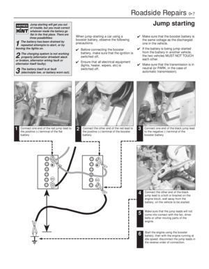 7
7 8
8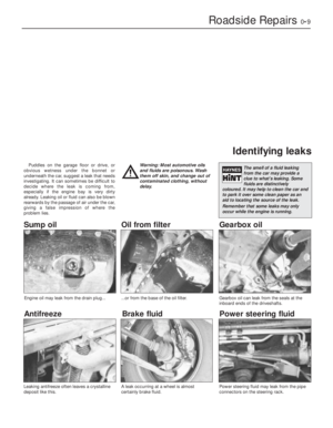 9
9 10
10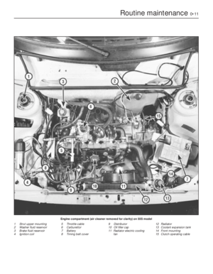 11
11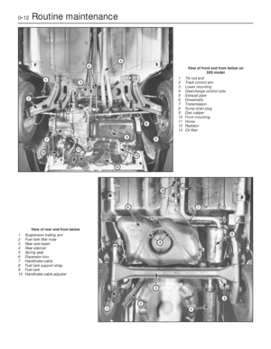 12
12 13
13 14
14 15
15 16
16 17
17 18
18 19
19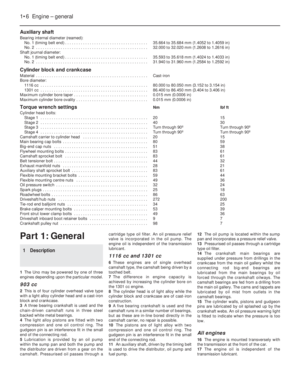 20
20 21
21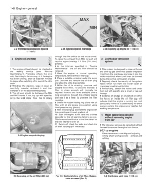 22
22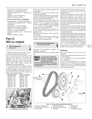 23
23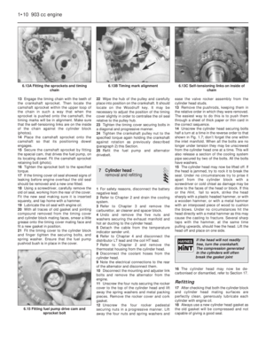 24
24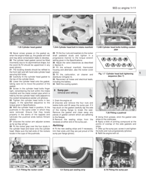 25
25 26
26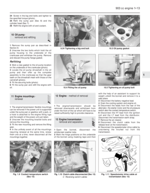 27
27 28
28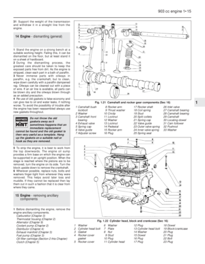 29
29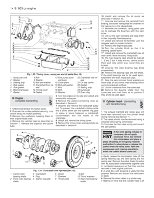 30
30 31
31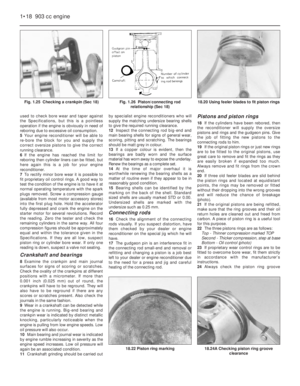 32
32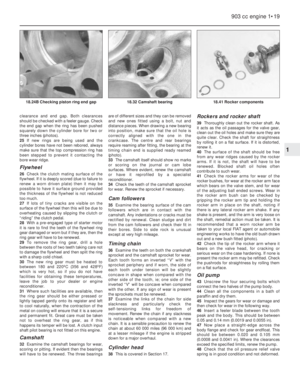 33
33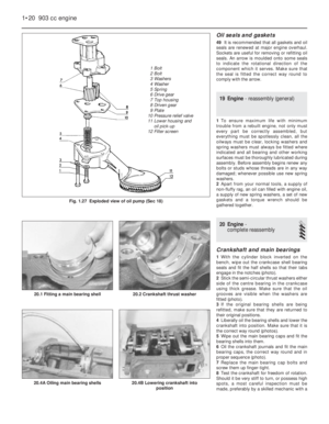 34
34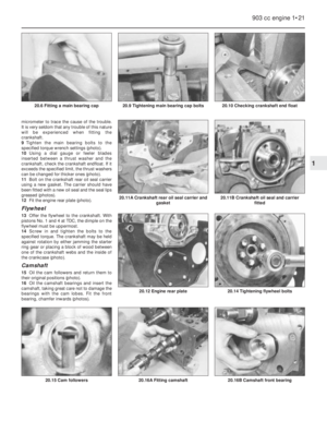 35
35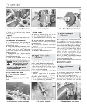 36
36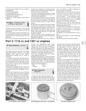 37
37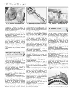 38
38 39
39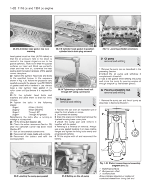 40
40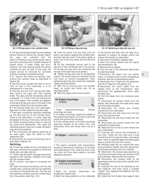 41
41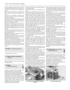 42
42 43
43 44
44 45
45 46
46 47
47 48
48 49
49 50
50 51
51 52
52 53
53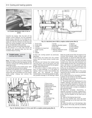 54
54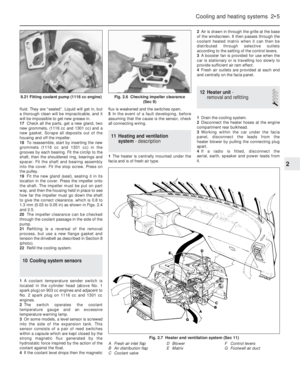 55
55 56
56 57
57 58
58 59
59 60
60 61
61 62
62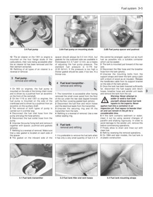 63
63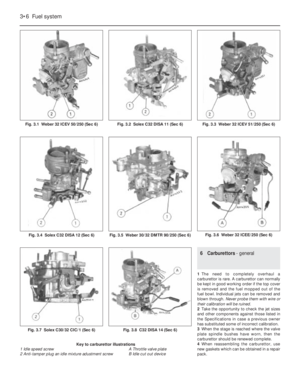 64
64 65
65 66
66 67
67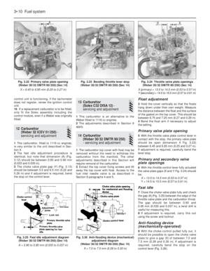 68
68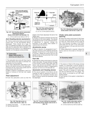 69
69 70
70 71
71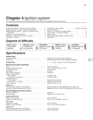 72
72 73
73 74
74 75
75 76
76 77
77 78
78 79
79 80
80 81
81 82
82 83
83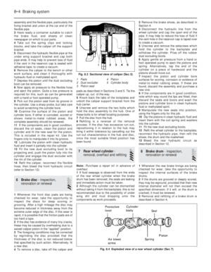 84
84 85
85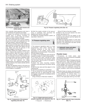 86
86 87
87 88
88 89
89 90
90 91
91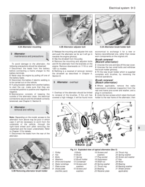 92
92 93
93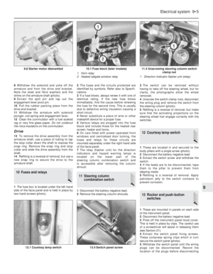 94
94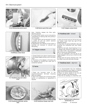 95
95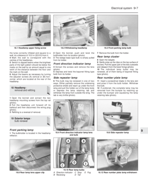 96
96 97
97 98
98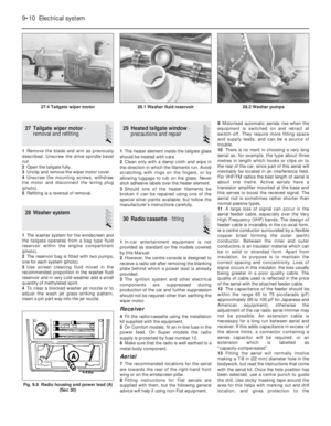 99
99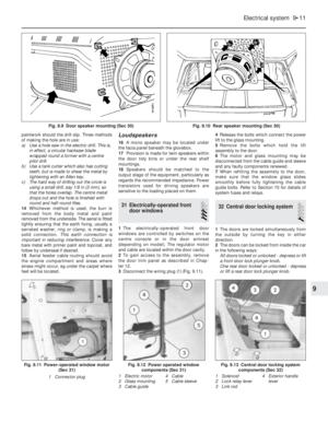 100
100 101
101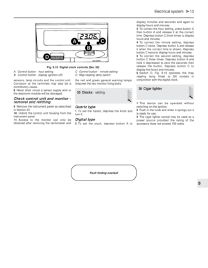 102
102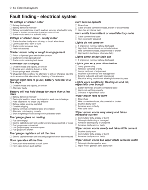 103
103 104
104 105
105 106
106 107
107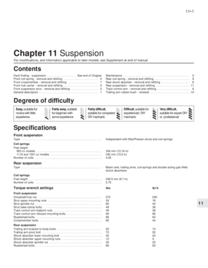 108
108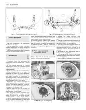 109
109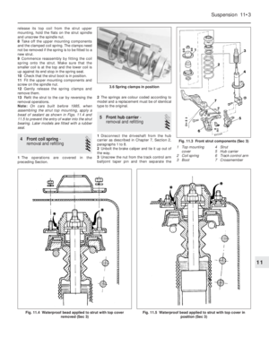 110
110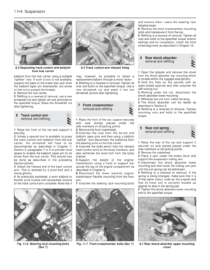 111
111 112
112 113
113 114
114 115
115 116
116 117
117 118
118 119
119 120
120 121
121 122
122 123
123 124
124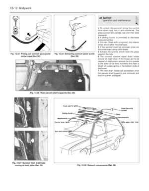 125
125 126
126 127
127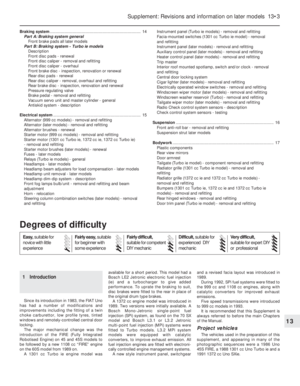 128
128 129
129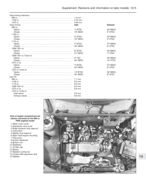 130
130 131
131 132
132 133
133 134
134 135
135 136
136 137
137 138
138 139
139 140
140 141
141 142
142 143
143 144
144 145
145 146
146 147
147 148
148 149
149 150
150 151
151 152
152 153
153 154
154 155
155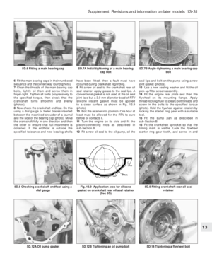 156
156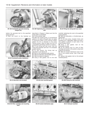 157
157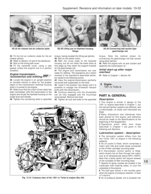 158
158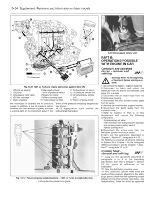 159
159 160
160 161
161 162
162 163
163 164
164 165
165 166
166 167
167 168
168 169
169 170
170 171
171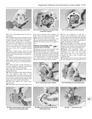 172
172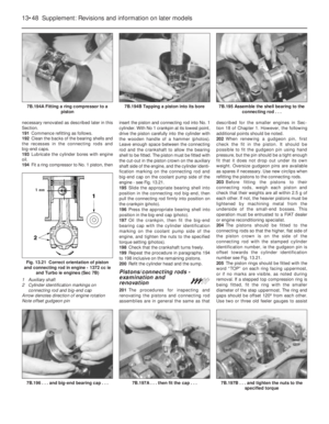 173
173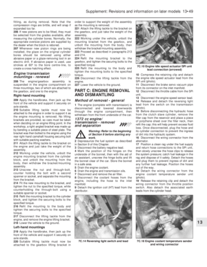 174
174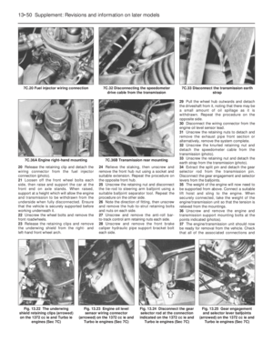 175
175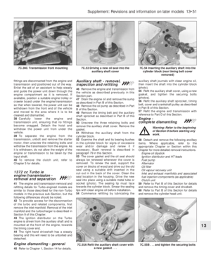 176
176 177
177 178
178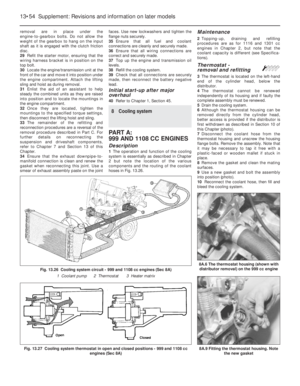 179
179 180
180 181
181 182
182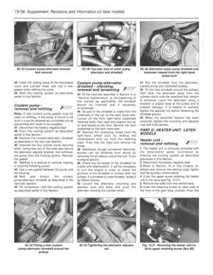 183
183 184
184 185
185 186
186 187
187 188
188 189
189 190
190 191
191 192
192 193
193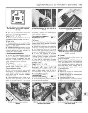 194
194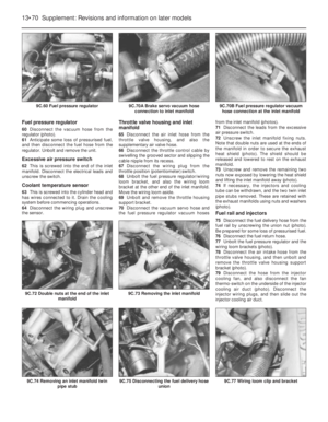 195
195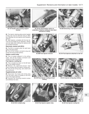 196
196 197
197 198
198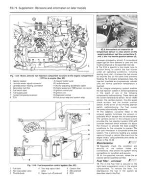 199
199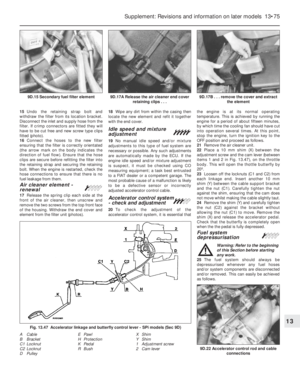 200
200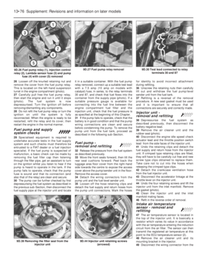 201
201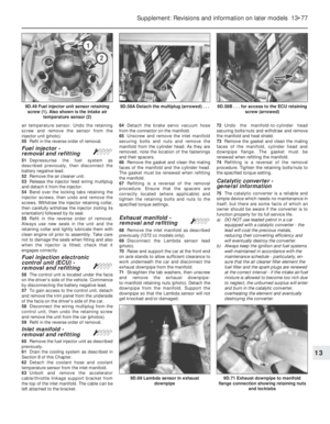 202
202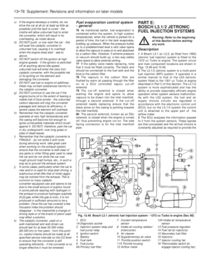 203
203 204
204 205
205 206
206 207
207 208
208 209
209 210
210 211
211 212
212 213
213 214
214 215
215 216
216 217
217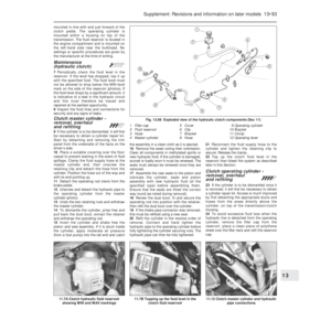 218
218 219
219 220
220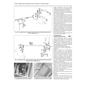 221
221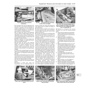 222
222 223
223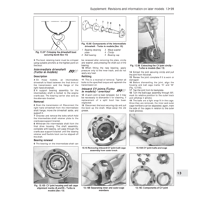 224
224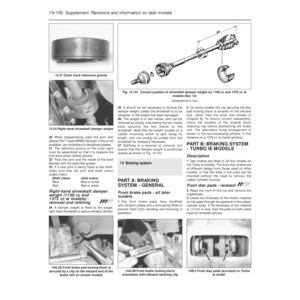 225
225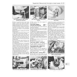 226
226 227
227 228
228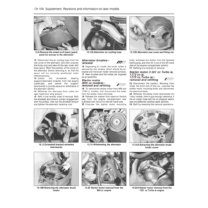 229
229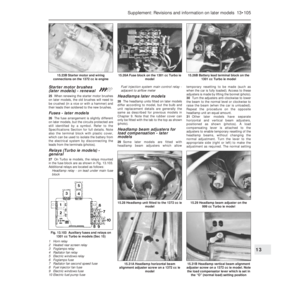 230
230 231
231 232
232 233
233 234
234 235
235 236
236 237
237 238
238 239
239 240
240 241
241 242
242 243
243 244
244 245
245 246
246 247
247 248
248 249
249 250
250 251
251 252
252 253
253 254
254 255
255 256
256 257
257 258
258 259
259 260
260 261
261 262
262 263
263 264
264 265
265 266
266 267
267 268
268 269
269 270
270 271
271 272
272 273
273 274
274 275
275 276
276 277
277 278
278 279
279 280
280 281
281 282
282 283
283 284
284 285
285 286
286 287
287 288
288 289
289 290
290 291
291 292
292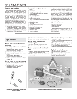 293
293 294
294 295
295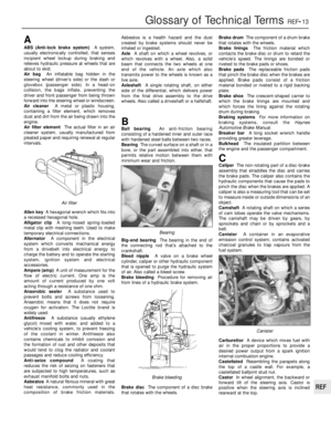 296
296 297
297 298
298 299
299 300
300 301
301 302
302
