1983 FIAT UNO engine coolant
[x] Cancel search: engine coolantPage 10 of 303

0•10Routine maintenance
Maintenance is essential for ensuring safety and desirable for the
purpose of getting the best in terms of performance and economy
from the car. Over the years the need for periodic lubrication has been
greatly reduced if not totally eliminated. This has unfortunately tended
to lead some owners to think that because no such action is required
the items either no longer exist or will last forever. This is certainly not
the case; it is essential to carry out regular visual examinations as
comprehensively as possible in order to spot any possible defects at
an early stage before they develop into major and expensive repairs.
For information applicable to later models, see Supplement.
Every 250 miles (400 km), weekly,
or before a long journey
m mCheck engine oil level
m mCheck brake reservoir fluid level
m mCheck tyre pressures
m mCheck operation of all lights and horn
m mTop up washer fluid reservoirs, adding a screen
wash, and check operation of washers and wipers
m mCheck coolant level
m mCheck battery electrolyte level
Every 6000 miles (10 000 km)
or six months, whichever comes first
m mRenew engine oil and filter (Chapter 1, Section 2)
m mCheck drivebelt tension (Chapter 2, Section 8)
m mCheck carburettor idle speed and mixture
adjustments (Chapter 3)
m mCheck contact points and dwell angle (mechanical
breaker distributors) (Chapter 4, Section 3)
m mCheck tyre tread wear (Chapter 7, Section 7)
m mCheck disc pads for wear (Chapter 8, Section 3)
Every 36 000 miles (60 000 km)
or three years, whichever comes first
m mRenew the timing belt - 1116 and 1299/1301 cc
(Chapter 1, Section 28)
m mCheck exhaust system for corrosion (Chapter 3,
Section 19)
m mRenew contact breaker points and adjust dwell
angle (mechanical breaker distributors) (Chapter 4,
Section 3)
m mCheck and adjust ignition timing (Chapter 4,
Section 4)
m mRenew spark plugs (Chapter 4, Section 11)
m mCheck clutch adjustment (Chapter 5, Section 2)
m mCheck transmission oil level (Chapter 6, Section 2)
m mCheck driveshaft and steering rack gaiters for splits
(Chapters 7 and 10)
m mCheck rear brake shoe linings for wear (Chapter 8,
Section 4)
m mCheck handbrake travel (Chapter 8, Section 16)
m mCheck headlamp beam alignment (Chapter 9,
Section 17)
m mCheck balljoints for wear (Chapter 10, Section 2)
m mCheck front wheel alignment (Chapter 10, Section 8)
m mCheck suspension bushes for wear (Chapter 11,
Section 2)
m mCheck seat belts for fraying (Chapter 12, Section 23)
m mLubricate controls, hinges and locks
Every 24 000 miles (40 000 km)
or two years, whichever comes first
m mRenew coolant anti-freeze mixture (Chapter 2,
Section 3)
m mRenew transmission oil (Chapter 6, Section 2)
m mRenew brake hydraulic fluid (Chapter 8, Section 12)
m mCheck for underbody corrosion and clean out door
and sill drain holes (Chapter 12, Section 2)
Every 12 000 miles (20 000 km) or
12 months, whichever comes first
m mCheck and adjust valve clearances (Chapter 1,
Sections 5 and 26)
m mRenew air cleaner element (Chapter 3, Section 2)
Page 11 of 303
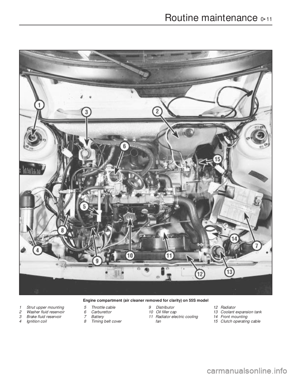
Routine maintenance0•11
Engine compartment (air cleaner removed for clarity) on 55S model
1 Strut upper mounting
2 Washer fluid reservoir
3 Brake fluid reservoir
4 Ignition coil5 Throttle cable
6 Carburettor
7 Battery
8 Timing belt cover9 Distributor
10 Oil filler cap
11 Radiator electric cooling
fan12 Radiator
13 Coolant expansion tank
14 Front mounting
15 Clutch operating cable
Page 24 of 303

13Engage the timing chain with the teeth of
the crankshaft sprocket. Then locate the
camshaft sprocket within the upper loop of
the chain in such a way that when the
sprocket is pushed onto the camshaft, the
timing marks will be in alignment. Make sure
that the self-tensioning links are on the inside
of the chain against the cylinder block
(photos).
14Place the camshaft sprocket onto the
camshaft so that its positioning dowel
engages.
15Secure the camshaft sprocket by fitting
the special cam, that drives the fuel pump, on
its locating dowel. Fit the camshaft sprocket
retaining bolt (photo).
16Tighten the sprocket bolt to the specified
torque.
17If the timing cover oil seal showed signs of
leaking before engine overhaul the old seal
should be removed and a new one fitted.
18Using a screwdriver, carefully remove the
old oil seal, working from the rear of the cover.
Fit the new seal making sure it is inserted
squarely, and tap home with a hammer.
19Lubricate the oil seal with engine oil.
20With all traces of old gasket and jointing
compound removed from the timing cover
and cylinder block mating faces, smear a little
grease onto the timing cover mating face and
fit a new gasket in position.
21Fit the timing cover to the cylinder block
and finger tighten the securing bolts, and
spring washer. Ensure that the fuel pump
pushrod bush is in place in the cover.22Wipe the hub of the pulley and carefully
place into position on the crankshaft. It should
locate on the Woodruff key. It may be
necessary to adjust the position of the timing
cover slightly in order to centralise the oil seal
relative to the pulley hub.
23Tighten the timing cover securing bolts in
a diagonal and progressive manner.
24Tighten the crankshaft pulley nut to the
specified torque again holding the crankshaft
against rotation as previously described
(paragraph 2) this Section.
25Refit the fuel pump and alternator
drivebelt.
7 Cylinder head-
removal and refitting
3
1For safety reasons, disconnect the battery
negative lead.
2Refer to Chapter 2 and drain the cooling
system.
3Refer to Chapter 3 and remove the
carburettor, air cleaner and spacer block.
4Undo and remove the five nuts and
washers securing the exhaust manifold and
hot air ducting to the cylinder head.
5Detach the cable from the temperature
indicator sender unit.
6Refer to Chapter 4 and disconnect the
distributor LT lead and the coil HT lead.
7Refer to Chapter 2 and remove the
thermostat housing from the cylinder head.
8Disconnect the coolant hoses from the
cylinder head.
9Note the electrical connections to the rear
of the alternator and disconnect them.
10Disconnect the mounting and adjuster link
bolts and remove the alternator from the
engine.
11Unscrew the four nuts securing the rocker
cover to the top of the cylinder head and lift
away the spring washers and metal packing
pieces. Remove the rocker cover and cork
gasket.
12Unscrew the four rocker pedestal
securing nuts in a progressive manner. Lift
away the four nuts and spring washers andease the valve rocker assembly from the
cylinder head studs.
13Remove the pushrods, keeping them in
the relative order in which they were removed.
The easiest way to do this is to push them
through a sheet of thick paper or thin card in
the correct sequence.
14Unscrew the cylinder head securing bolts
half a turn at a time in the reverse order to that
shown in Fig. 1.7; don’t forget the one within
the inlet manifold. When all the bolts are no
longer under tension they may be unscrewed
from the cylinder head one at a time. This will
also release a section of the cooling system
pipe secured by two of the bolts. All the bolts
have washers.
15The cylinder head may now be lifted off. If
the head is jammed, try to rock it to break the
seal. Under no circumstances try to prise it
apart from the cylinder block with a
screwdriver or cold chisel as damage may be
done to the faces of the head or block. If this
or the Hint, fail to work, strike the head
sharply with a plastic headed hammer, or with
a wooden hammer, or with a metal hammer
with an interposed piece of wood to cushion
the blows. Under no circumstances hit the
head directly with a metal hammer as this may
cause the casting to fracture. Several sharp
taps with the hammer, at the same time
pulling upwards, should free the head. Lift the
head off and place on one side.
16The cylinder head may now be de-
carbonised or dismantled, refer to Section 17.
Refitting
17After checking that both the cylinder block
and cylinder head mating surfaces are
perfectly clean, generously lubricate each
cylinder with engine oil.
18Always use a new cylinder head gasket as
the old gasket will be compressed and not
capable of giving a good seal.
1•10 903 cc engine
6.15 Fitting fuel pump drive cam and
sprocket bolt
6.13C Self-tensioning links on inside of
chain6.13B Timing mark alignment6.13A Fitting the sprockets and timing
chain
If the head will not readily
free, turn the crankshaft.
The compression generated
in the cylinders will often
break the gasket joint
Page 25 of 303
19Never smear grease on the gasket as,
when the engine heats up, the grease will melt
and may allow compression leaks to develop.
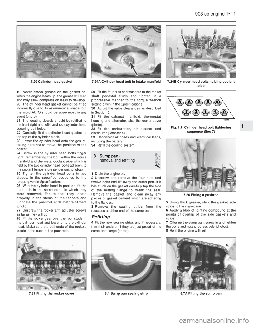
20The cylinder head gasket cannot be fitted
incorrectly due to its asymmetrical shape, but
the word ALTO should be uppermost in any
event (photo).
21The locating dowels should be refitted to
the front right and left-hand side cylinder head
securing bolt holes.
22Carefully fit the cylinder head gasket to
the top of the cylinder block.
23Lower the cylinder head onto the gasket,
taking care not to move the position of the
gasket.
24Screw in the cylinder head bolts finger
tight, remembering the bolt within the intake
manifold and the metal coolant pipe which is
held by the two cylinder head bolts adjacent to
the coolant temperature sender unit (photos).
25Tighten the cylinder head bolts in two
stages, in the specified sequence to the
torque given in Specifications.
26With the cylinder head in position, fit the
pushrods in the same order in which they
were removed. Ensure that they locate
properly in the stems of the tappets and
lubricate the pushrod ends before fitment
(photo).
27Unscrew the rocker arm adjuster screws
as far as they will go.
28Fit the rocker gear over the four studs in
the cylinder head and lower onto the cylinder
head. Make sure the ball ends of the rockers
locate in the cups of the pushrods.29Fit the four nuts and washers to the rocker
shaft pedestal studs and tighten in a
progressive manner to the torque wrench
setting given in the Specifications.
30Adjust the valve clearances as described
in Section 5.
31Fit the exhaust manifold, thermostat
housing and alternator, also the rocker cover
(photo).
32Fit the carburettor, air cleaner and
distributor (Chapter 4).
33Reconnect all hoses and electrical leads,
including the battery.
34Refill the cooling system.
8 Sump pan-
removal and refitting
1
1Drain the engine oil.
2Unscrew and remove the four nuts and
twelve bolts and lift away the sump pan. If it
has stuck on the gasket carefully tap the side
of the mating flange to break the seal.
Remove the gasket and clean away any
pieces of gasket cement which are adhering
to the flanges.
3Remove the sealing strips from the
recesses at either end of the sump pan.
Refitting
4Fit the new sealing strips and if necessary,
trim their ends until they are just proud of the
sump pan flange (photo).5Using thick grease, stick the gasket side
strips to the crankcase.
6Apply a blob of jointing compound at the
points of overlap of the side gaskets and
strips.
7Offer up the sump pan, screw in and tighten
the bolts and nuts progressively (photos).
8Refill the engine with oil.
903 cc engine 1•11
7.24B Cylinder head bolts holding coolant
pipe7.24A Cylinder head bolt in intake manifold7.20 Cylinder head gasket
7.31 Fitting the rocker cover
7.26 Fitting a pushrod
Fig. 1.7 Cylinder head bolt tightening
sequence (Sec 7)1
8.4 Sump pan sealing strip8.7A Fitting the sump pan
Page 27 of 303
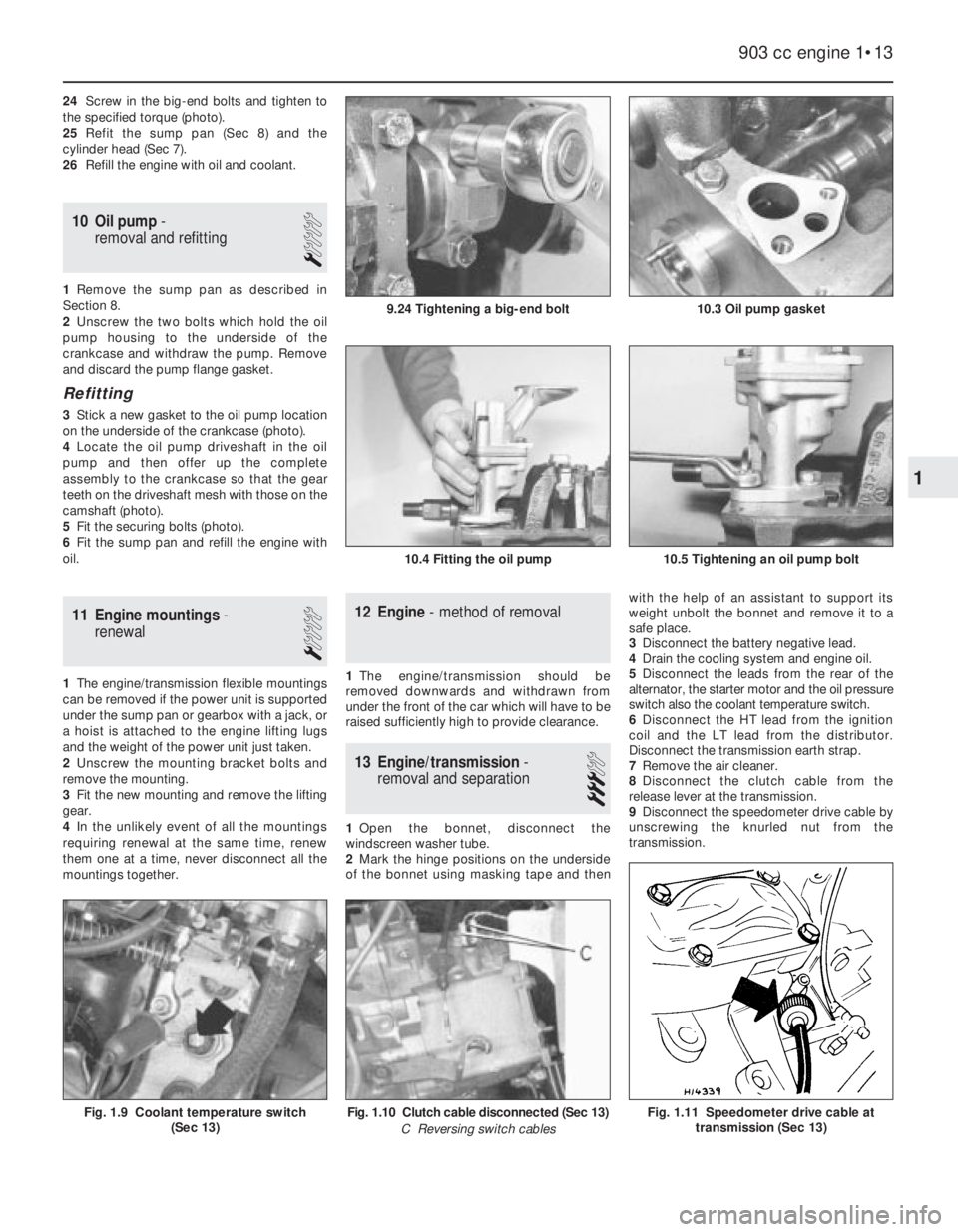
24Screw in the big-end bolts and tighten to
the specified torque (photo).
25Refit the sump pan (Sec 8) and the
cylinder head (Sec 7).
26Refill the engine with oil and coolant.
10 Oil pump-
removal and refitting
1
1Remove the sump pan as described in
Section 8.
2Unscrew the two bolts which hold the oil
pump housing to the underside of the
crankcase and withdraw the pump. Remove
and discard the pump flange gasket.
Refitting
3Stick a new gasket to the oil pump location
on the underside of the crankcase (photo).
4Locate the oil pump driveshaft in the oil
pump and then offer up the complete
assembly to the crankcase so that the gear
teeth on the driveshaft mesh with those on the
camshaft (photo).
5Fit the securing bolts (photo).
6Fit the sump pan and refill the engine with
oil.
11 Engine mountings-
renewal
1
1The engine/transmission flexible mountings
can be removed if the power unit is supported
under the sump pan or gearbox with a jack, or
a hoist is attached to the engine lifting lugs
and the weight of the power unit just taken.
2Unscrew the mounting bracket bolts and
remove the mounting.
3Fit the new mounting and remove the lifting
gear.
4In the unlikely event of all the mountings
requiring renewal at the same time, renew
them one at a time, never disconnect all the
mountings together.
12 Engine- method of removal
1The engine/transmission should be
removed downwards and withdrawn from
under the front of the car which will have to be
raised sufficiently high to provide clearance.
13 Engine/transmission-
removal and separation
3
1Open the bonnet, disconnect the
windscreen washer tube.
2Mark the hinge positions on the underside
of the bonnet using masking tape and thenwith the help of an assistant to support its
weight unbolt the bonnet and remove it to a
safe place.
3Disconnect the battery negative lead.
4Drain the cooling system and engine oil.
5Disconnect the leads from the rear of the
alternator, the starter motor and the oil pressure
switch also the coolant temperature switch.
6Disconnect the HT lead from the ignition
coil and the LT lead from the distributor.
Disconnect the transmission earth strap.
7Remove the air cleaner.
8Disconnect the clutch cable from the
release lever at the transmission.
9Disconnect the speedometer drive cable by
unscrewing the knurled nut from the
transmission.
903 cc engine 1•13
10.3 Oil pump gasket
10.4 Fitting the oil pump10.5 Tightening an oil pump bolt
9.24 Tightening a big-end bolt
Fig. 1.11 Speedometer drive cable at
transmission (Sec 13)Fig. 1.10 Clutch cable disconnected (Sec 13)
C Reversing switch cablesFig. 1.9 Coolant temperature switch
(Sec 13)
1
Page 28 of 303
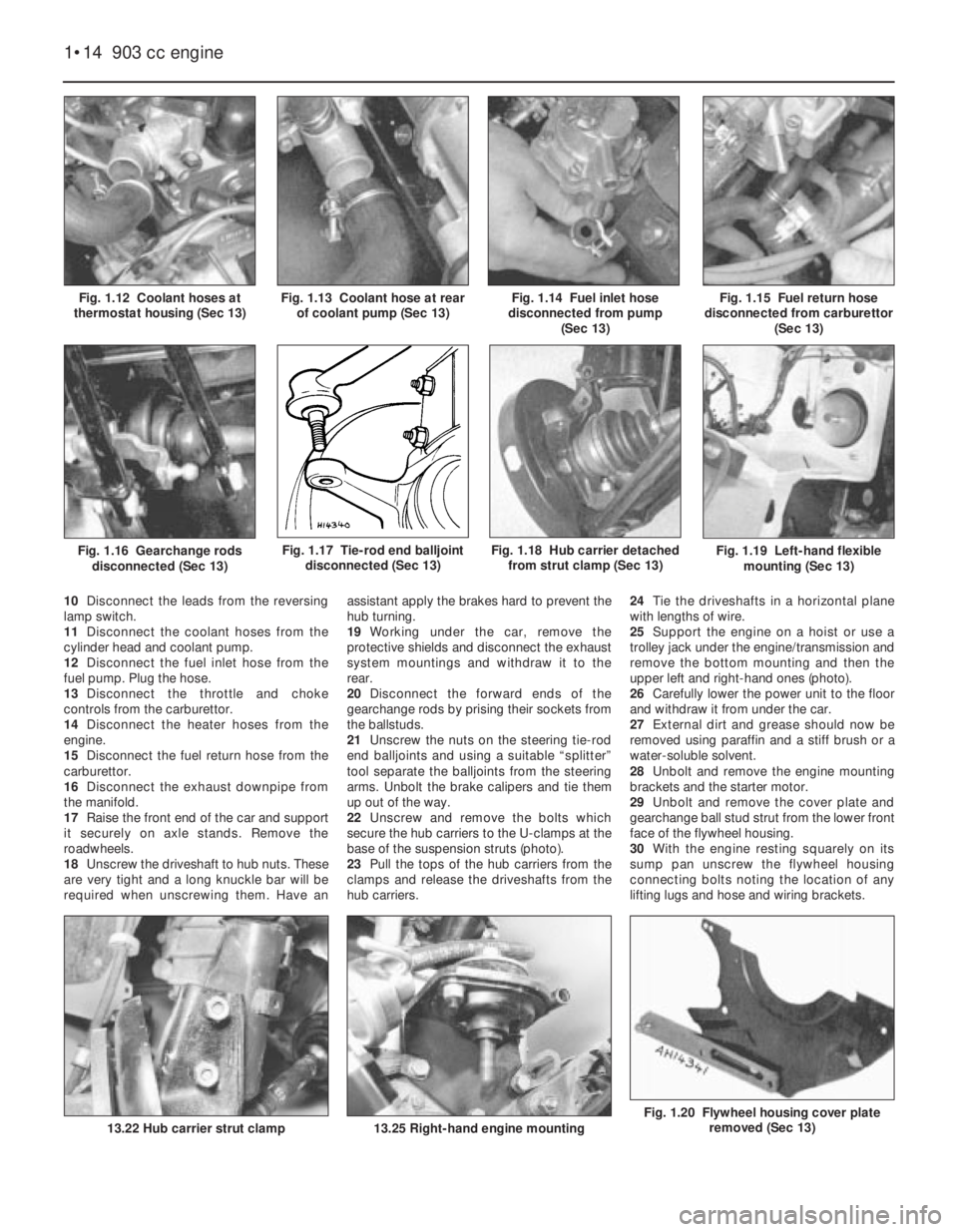
Fig. 1.20 Flywheel housing cover plate
removed (Sec 13)
Fig. 1.19 Left-hand flexible
mounting (Sec 13)
10Disconnect the leads from the reversing
lamp switch.
11Disconnect the coolant hoses from the
cylinder head and coolant pump.
12Disconnect the fuel inlet hose from the
fuel pump. Plug the hose.
13Disconnect the throttle and choke
controls from the carburettor.
14Disconnect the heater hoses from the
engine.
15Disconnect the fuel return hose from the
carburettor.
16Disconnect the exhaust downpipe from
the manifold.
17Raise the front end of the car and support
it securely on axle stands. Remove the
roadwheels.
18Unscrew the driveshaft to hub nuts. These
are very tight and a long knuckle bar will be
required when unscrewing them. Have anassistant apply the brakes hard to prevent the
hub turning.
19Working under the car, remove the
protective shields and disconnect the exhaust
system mountings and withdraw it to the
rear.
20Disconnect the forward ends of the
gearchange rods by prising their sockets from
the ballstuds.
21Unscrew the nuts on the steering tie-rod
end balljoints and using a suitable “splitter”
tool separate the balljoints from the steering
arms. Unbolt the brake calipers and tie them
up out of the way.
22Unscrew and remove the bolts which
secure the hub carriers to the U-clamps at the
base of the suspension struts (photo).
23Pull the tops of the hub carriers from the
clamps and release the driveshafts from the
hub carriers.24Tie the driveshafts in a horizontal plane
with lengths of wire.
25Support the engine on a hoist or use a
trolley jack under the engine/transmission and
remove the bottom mounting and then the
upper left and right-hand ones (photo).
26Carefully lower the power unit to the floor
and withdraw it from under the car.
27External dirt and grease should now be
removed using paraffin and a stiff brush or a
water-soluble solvent.
28Unbolt and remove the engine mounting
brackets and the starter motor.
29Unbolt and remove the cover plate and
gearchange ball stud strut from the lower front
face of the flywheel housing.
30With the engine resting squarely on its
sump pan unscrew the flywheel housing
connecting bolts noting the location of any
lifting lugs and hose and wiring brackets.
1•14 903 cc engine
13.25 Right-hand engine mounting
Fig. 1.18 Hub carrier detached
from strut clamp (Sec 13)
13.22 Hub carrier strut clamp
Fig. 1.17 Tie-rod end balljoint
disconnected (Sec 13)Fig. 1.16 Gearchange rods
disconnected (Sec 13)
Fig. 1.15 Fuel return hose
disconnected from carburettor
(Sec 13)Fig. 1.14 Fuel inlet hose
disconnected from pump
(Sec 13)Fig. 1.13 Coolant hose at rear
of coolant pump (Sec 13)Fig. 1.12 Coolant hoses at
thermostat housing (Sec 13)
Page 29 of 303
31Support the weight of the transmission
and withdraw it in a straight line from the
engine.
14 Engine- dismantling (general)
1Stand the engine on a strong bench at a
suitable working height. Failing this, it can be
dismantled on the floor, but at least stand it
on a sheet of hardboard.
2During the dismantling process, the
greatest care should be taken to keep the
exposed parts free from dirt. As the engine is
stripped, clean each part in a bath of paraffin.
3Never immerse parts with oilways in
paraffin, e.g. the crankshaft, but to clean,
wipe down carefully with a paraffin dampened
rag. Oilways can be cleaned out with a piece
of wire. If an air line is available, all parts can
be blown dry and the oilways blown through
as an added precaution.
4Re-use of old gaskets is false economy and
can give rise to oil and water leaks, if nothing
worse. To avoid the possibility of trouble after
the engine has been reassembled always use
new gaskets throughout.
5To strip the engine, it is best to work from
the top downwards. The engine oil sump
provides a firm base on which the engine can
be supported in an upright position. When the
stage is reached where the pistons are to be
removed, turn the engine on its side. Turn the
block upside down to remove the crankshaft.
6Wherever possible, replace nuts, bolts and
washers finger-tight from wherever they were
removed. This helps avoid later loss and
muddle. If they cannot be replaced then lay
them out in such a fashion that it is clear from
where they came.
15 Engine- removing ancillary
components
1Before dismantling the engine, remove the
engine ancillary components.
Carburettor (Chapter 3)
Thermostat housing (Chapter 2)
Alternator (Chapter 9)
Coolant pump (Chapter 2)
Distributor (Chapter 4)
Exhaust manifold (Chapter 3)
Fuel pump (Chapter 3)
Oil filter cartridge (Section 2 this Chapter)
Clutch (Chapter 5)
903 cc engine 1•15
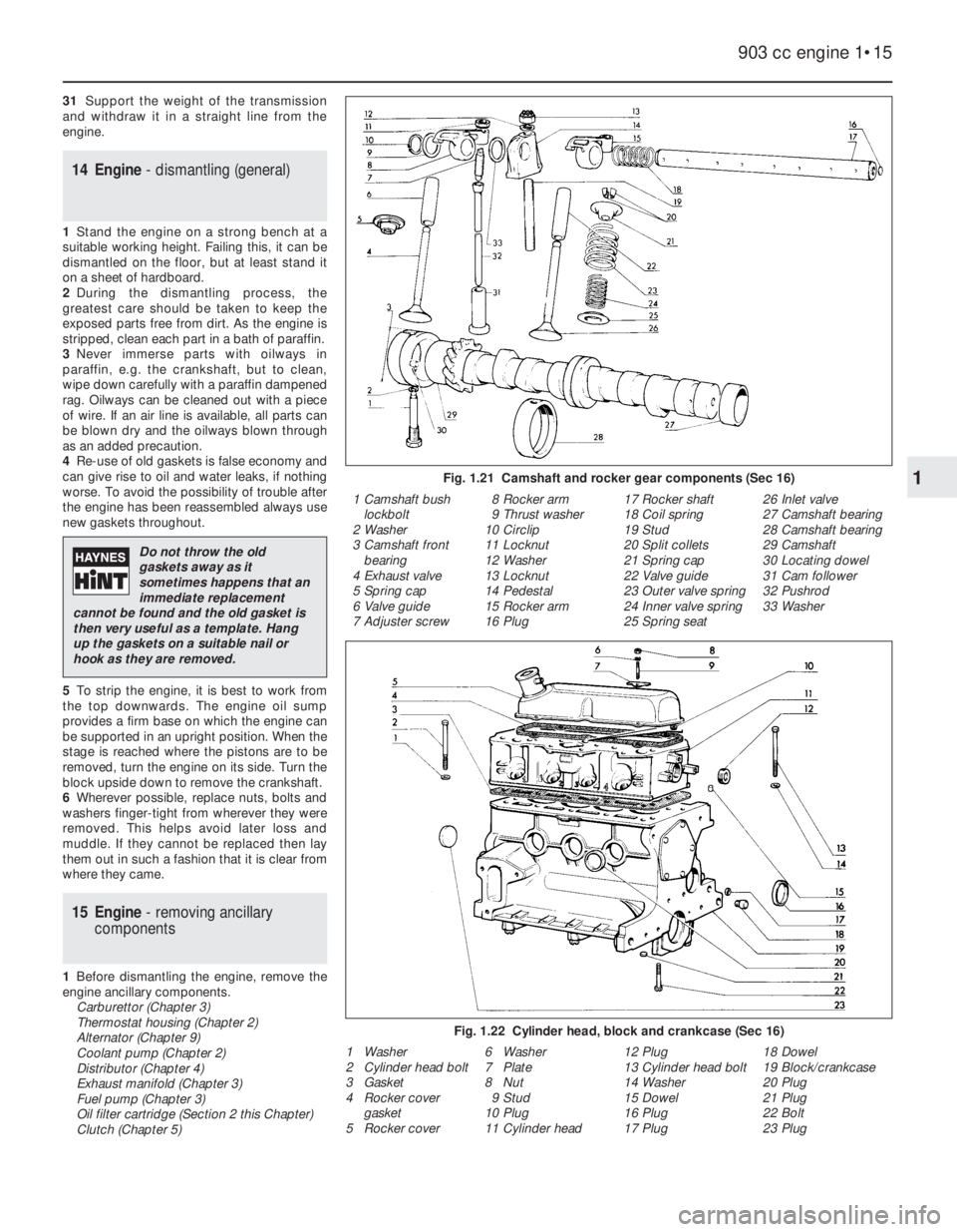
Fig. 1.21 Camshaft and rocker gear components (Sec 16)
Fig. 1.22 Cylinder head, block and crankcase (Sec 16)
1 Camshaft bush
lockbolt
2 Washer
3 Camshaft front
bearing
4 Exhaust valve
5 Spring cap
6 Valve guide
7 Adjuster screw8 Rocker arm
9 Thrust washer
10 Circlip
11 Locknut
12 Washer
13 Locknut
14 Pedestal
15 Rocker arm
16 Plug17 Rocker shaft
18 Coil spring
19 Stud
20 Split collets
21 Spring cap
22 Valve guide
23 Outer valve spring
24 Inner valve spring
25 Spring seat26 Inlet valve
27 Camshaft bearing
28 Camshaft bearing
29 Camshaft
30 Locating dowel
31 Cam follower
32 Pushrod
33 Washer
1 Washer
2 Cylinder head bolt
3 Gasket
4 Rocker cover
gasket
5 Rocker cover6 Washer
7 Plate
8 Nut
9 Stud
10 Plug
11 Cylinder head12 Plug
13 Cylinder head bolt
14 Washer
15 Dowel
16 Plug
17 Plug18 Dowel
19 Block/crankcase
20 Plug
21 Plug
22 Bolt
23 Plug
1
Do not throw the old
gaskets away as it
sometimes happens that an
immediate replacement
cannot be found and the old gasket is
then very useful as a template. Hang
up the gaskets on a suitable nail or
hook as they are removed.
Page 31 of 303

light alloy construction and is easily damaged
use a blunt scraper or rotary wire brush to
clean all traces of carbon deposits from the
combustion spaces and the ports. The valve
head stems and valve guides should also be
freed from any carbon deposits. Wash the
combustion spaces and ports down with
paraffin and scrape the cylinder head surface
free of any foreign matter with the side of a
steel rule, or a similar article.
8If the engine is installed in the car, clean the
pistons and the top of the cylinder bores. If
the pistons are still in the block, then it is
essential that great care is taken to ensure
that no carbon gets into the cylinder bores as
this could scratch the cylinder walls or cause
damage to the piston and rings. To ensure
this does not happen, first turn the crankshaft
so that two of the pistons are at the top of
their bores. Stuff rag into the other two bores
or seal them off with paper and masking tape.
The waterways should also be covered with
small pieces of masking tape to prevent
particles of carbon entering the cooling
system and damaging the coolant pump.
9With a blunt scraper carefully scrape away
the carbon from the piston crown, taking care
not to scratch the aluminium. Also scrape
away the carbon from the surrounding lip of
the cylinder wall. When all carbon has been
removed, scrape away the grease which will
now be contaminated with carbon particles,
taking care not to press any into the bores. To
assist prevention of carbon build-up the
piston crown can be polished with a metal
polish. Remove the rags or masking tape from
the other two cylinders and turn the
crankshaft so that the two pistons which were
at the bottom are now at the top. Place rag in
the cylinders which have been decarbonised,
and proceed as just described.
10Examine the head of the valves for pitting
and burning, especially the heads of the
exhaust valves. The valve seatings should be
examined at the same time. If the pitting on
the valve and seat is very slight, the markscan be removed by grinding the seats and
valves together with coarse, and then fine,
valve grinding paste.
11Where bad pitting has occurred to the
valve seats it will be necessary to recut them
and fit new valves. This latter job should be
entrusted to the local agent or engineering
works. In practice it is very seldom that the
seats are so badly worn. Normally it is the
valve that is too badly worn for refitting, and
the owner can easily purchase a new set of
valves and match them to the seats by valve
grinding.
12Valve grinding is carried out as follows.
Smear a trace of coarse carborundum paste
on the seat face and apply a suction grinder
tool to the valve head. With a semi-rotary
motion, grind the valve head to its seat, lifting
the valve occasionally to redistribute the
grinding paste. When a dull matt even surface
is produced on both the valve seat and the
valve, wipe off the paste and repeat the
process with fine carborundum paste, lifting
and turning the valve to redistribute the paste
as before. A light spring placed under the
valve head will greatly ease this operation.
When a smooth unbroken ring of light grey
matt finish is produced, on both valve and
valve seat faces, the grinding operation is
complete. Carefully clean away every trace of
grinding compound, take great care to leave
none in the ports or in the valve guides. Clean
the valve seats with a paraffin soaked rag,
then with a clean rag, and finally, if an air line
is available, blow the valves, valve guides and
valve ports clean.
13Check that all valve springs are intact. If
any one is broken, all should be renewed.
Check the free height of the springs against
new ones. If some springs are not within
specifications, replace them all. Springs suffer
from fatigue and it is a good idea to renew
them even if they look serviceable.
14Check that the oil supply holes in the
rocker arms are clear.
15The cylinder head can be checked for
warping either by placing it on a piece of plate
glass or using a straight-edge and feeler
blades. If there is any doubt or if its block face
is corroded, have it re-faced by your dealer or
motor engineering works.
16Test the valves in their guides for side toside rock. If this is any more than almost
imperceptible, new guides must be fitted.
Again this is a job for your dealer as a special
tool is required to ensure the correct
installation depth and the cylinder head must
be warmed to 80ºC (176ºF) before fitting the
guides.
17Commence reassembly by oiling the stem
of the first valve and pushing it into its guide
which should have been fitted with a new oil
seal (photos).
18Fit the spring seat. Fit the valve spring so
that the closer coils are towards the cylinder
head and then fit the spring retaining cap.
19Compress the valve spring and locate the
split cotters in the valve stem cut-out (photo).
20Gently release the compressor, checking
to see that the collets are not displaced.
21Fit the remaining valves in the same way.
22Tap the end of each valve stem with a
plastic or copper-faced hammer to settle the
components.
23The cylinder head is now ready for
refitting as described in Section 7.
18 Examination and renovation
4
1With the engine stripped down and all parts
thoroughly clean, it is now time to examine
everything for wear. The following items
should be checked and where necessary
renewed or renovated as described in the
following Sections.
Cylinder block and crankcase
2Examine the casting carefully for cracks
especially around the bolt holes and between
cylinders.
3The cylinder bores must be checked for
taper, ovality, scoring and scratching. Start by
examining the top of the cylinder bores. If they
are at all worn, a ridge will be felt on the thrust
side. This ridge marks the limit of piston ring
travel. The owner will have a good indication
of bore wear prior to dismantling by the
quantity of oil consumed and the emission of
blue smoke from the exhaust especially when
the engine is cold.
4An internal micrometer or dial gauge can be
903 cc engine 1•17
17.19 Fitting split collets17.17B Inserting a valve into its guide17.17A Valve stem oil seal
1
Press a little grease into the
gap between the cylinder
walls and the two pistons
which are to be worked on.