Page 225 of 303

20When reassembling, pack the joint with
special FIAT Tutela MRM2 lubricant; if this is not
available, use molybdenum disulphide grease.
21The reference groove on the outer track
must be assembled so that it is towards the
final drive when refitted (photo).
22Pack the joint and the inside of the boot
liberally with the specified grease.
23If a new joint is being fitted to the shaft,
make sure that the joint and shaft colour
codes match.
Shaft colour Joint colour
Blue Blue or white
Red Red or white
Right-hand driveshaft damper
weight (1108 cc and
1372 cc ie models) -
removal and refitting
#
24A damper weight is fitted to the longer,
right-hand driveshaft to reduce vibration (photo).25It should not be necessary to remove the
damper weight unless the driveshaft is to be
renewed, or the weight has been damaged.
26The weight is in two halves, and can be
removed by simply unscrewing the two clamp
bolts securing the two halves to the
driveshaft. Note that the weight locates on a
rubber mounting which is split along its
length, and can simply be pulled from the
driveshaft for renewal if necessary.
27Refitting is a reversal of removal, but
ensure that the damper weight is positioned
exactly as shown in Fig. 13.101.
14 Braking system
PART A: BRAKING
SYSTEM - GENERAL
Front brake pads - all later
models
1The front brake pads have modified
anti-vibration plates and a wire spring fitted to
prevent them from vibrating and knocking in
operation. 2On some models the clip securing the disc
pad locking block is located on the inboard
end, rather than the outer end (shown in
Chapter 8). To ensure correct reassembly,
check the location of the original block
retaining clip before dismantling the brake
unit. The alternative fixing arrangement is
shown in the accompanying photos, in this
instance on a 1372 cc ie model (photos).
PART B: BRAKING SYSTEM
- TURBO IE MODELS
Description
1Disc brakes are fitted to all four wheels on
the Turbo ie models. The front disc brakes are
of different design from those used on other
models, in that the wear in the pads can be
checked without the need to remove the
caliper cylinder housing.
Front disc pads - renewalª
2Raise the front of the car and remove the
roadwheels.
3Check the thickness of the friction material
on the pads through the aperture in the caliper
cylinder body. If the thickness of the material
is 1.5 mm or less, then the pads on both sides
must be renewed (photo).
13•100 Supplement: Revisions and information on later models
14B.3 Front disc pads (arrowed) on Turbo
ie model14A.2B Front brake locking block
orientation with inboard retaining clip14A.2A Front brake pad locking block is
secured by a clip on the inboard end of the
brake unit on certain models
Fig. 13.101 Correct position of driveshaft damper weight on 1108 cc and 1372 cc ie
models (Sec 13)
Dimensions in mm
13.24 Right-hand driveshaft damper weight
13.21 Outer track reference groove
Page 226 of 303
.
Release the upper bolt, but do not remove it.
5Swivel the cylinder housing up")
4Using a ring spanner and an open-ended
spanner, unscrew and remove the caliper
cylinder housing lower guide bolt (photo).
Release the upper bolt, but do not remove it.
5Swivel the cylinder housing upwards and tie
it up out of the way. There is no need to
disconnect the hydraulic hose. The sensor
wiring plug will have to be disconnected
(where fitted).
6Remove the pads, complete with anti-rattle
springs (photo).
7Clean away all dust and dirt, taking care not
to inhale it as it may be injurious to health.
8The caliper piston must now be fully
depressed to accommodate the new, thicker,
pads. Do this using a G-clamp or lever, but
anticipate a rise in the brake fluid reservoir
level by syphoning out some of the fluid using
a clean syringe.
9Fit the new pads, which must be of the
same type as the originals, complete with
anti-rattle springs.
10Locate the cylinder body. The fixing bolts
are of self-locking type, and should be
renewed whenever they are loosened or
removed. If new ones are not available, clean
the threads of the old ones thoroughly and
apply thread-locking fluid (photo). Tighten the
bolts to the specified torque. Check that the
rubber dust excluders are in good condition.
11Reconnect the sensor wiring plug.
12Renew the pads on the other front wheel.
13Refit the roadwheels, and then apply the
footbrake several times to position the pads
against the discs.14Top up the brake fluid reservoir if
necessary (photo).
Front disc caliper -
removal and refitting#
15Raise the front of the car and remove the
appropriate roadwheel.
16Using a ring spanner and an open-ended
spanner, unscrew and remove the cylinder
housing fixing bolts.
17Withdraw the cylinder housing, and then,
holding it firmly, release the flexible hydraulic
hose union. Unscrew the cylinder body from
the end of the flexible hose, and then cap the
end of the hose to prevent loss of fluid.
18If required, the disc pads can be removed
and the caliper support bracket unbolted and
removed.
19Refitting is a reversal of removal, but use
new fixing bolts.
20Bleed the front hydraulic circuit.
Front disc caliper - overhaul
21The operations are as described in
Chapter 8, Section 5, paragraphs 6 to 13.
Front brake disc - inspection,
renovation or renewal
22The operations are as described in
Chapter 8, Section 6, but the caliper fixing
bolts are secured with thread-locking fluid;
lockplates are not used.
Rear disc pads - renewal ª
23Any wear in the disc pads can be
observed through the aperture in the calipercylinder body, once the car has been jacked
up and the roadwheels removed (photo).
24If the thickness of the pad friction material
is less than 1.5 mm, renew the pads on both
sides in the following way.
25Using a ring spanner and an open-ended
spanner, unscrew the caliper cylinder body
fixing bolts.
26Withdraw the caliper and remove the disc
pads, complete with anti-rattle springs (photo).
27Clean away all dust and dirt, but avoid
inhaling it, as it may be injurious to health.
28Fully retract the caliper piston in order to
accommodate the new, thicker, pads. To do
this, rotate the piston clockwise, using a
suitable tool engaged in the handbrake
sectors (photo). Anticipate a rise in the brake
fluid reservoir level by syphoning out some
fluid, using a clean syringe.
Supplement: Revisions and information on later models 13•101
14B.10 Applying thread-locking fluid to the
bolt threads14B.6 Disc pad and anti-rattle spring
removal14B.4 Unscrewing the caliper cylinder
housing lower guide bolt
14B.28 Rotating a rear caliper piston14B.26 Withdrawing the rear brake caliper14B.23 Rear brake pad inspection aperture
14B.14 Topping up the brake fluid reservoir
(1301 cc Turbo ie model)
13
Page 227 of 303

29Fit the new pads, complete with anti-rattle
springs (photo).
30Refit the caliper using new sel")
14B.54 Master cylinder/vacuum servo
located next to the coolant expansion tank
(1301 cc Turbo ie model)
29Fit the new pads, complete with anti-rattle
springs (photo).
30Refit the caliper using new self-locking
bolts, or if not available, apply thread-locking
fluid to clean threads of the original bolts.
Tighten the bolts to the specified torque.
31Apply the brake pedal several times to
bring the disc pads up against the disc.
32Top up the brake fluid reservoir if
necessary.
33Check the adjustment of the handbrake.
34Refit the roadwheels and lower the car to
the ground.
Rear disc caliper -
removal, overhaul and
refitting
¢
35Carry out the operations described in
paragraphs 25 to 27.36Disconnect the handbrake cable from the
caliper. To do this, grip the cable nipple and
pull it until the cable can be slipped out of its
lever groove (photo). If necessary, slacken the
cable adjustment.
37Using a pair of pliers or similar tool, turn
the piston in an anti-clockwise direction until it
can be removed from the cylinder.
38Having obtained a repair kit, renew the
seal and dust excluder.
39Reassemble the piston to the cylinder,
turning it clockwise as far as it will go.
40Reconnect the handbrake cable.
41Carry out the operations described in
paragraphs 30 to 32.
Rear brake disc -
inspection, renovation
or renewal
ª
42The operations are as described in
Chapter 8, Section 6, but the caliper bracket
fixing bolts are of the socket-headed type and
thread-locking fluid is used, not lockplates
(photo).
Pressure regulating valve
43The valve renewal and adjustment
operations are described in Chapter 8,
Section 10, but the luggage compartment
should be loaded with 45 kg and the load
applied to the bracket eye should be 11 kg.
Brake pedal -
removal and refitting#
44The brake master cylinder and vacuum
servo are mounted on the left-hand side of theengine compartment rear bulkhead. In conse-
quence, the brake pedal on right-hand drive
cars operates through a cross-shaft, which is
located underneath the facia panel inside the
car.
45The cross-shaft is supported in two
brackets, whose mounting nuts can be
reached through cut-outs in the insulation on
the engine compartment rear bulkhead (photo).
46To remove the cross-shaft, working inside
the car, take off the cover from the left-hand
end of the shaft, and then disconnect the
servo pushrod from the crankarm on the
cross-shaft (photo).
47Disconnect the brake pedal from the
right-hand crankarm on the cross-shaft
(photo).
48Disconnect the accelerator pedal by
extracting the split pin which secures its pivot
spindle.
49The cross-shaft may now be removed
after extracting the cotter pin from the
left-hand end of the shaft.
50Push the shaft first to the right, and then
to the left, to release it from its brackets.
51Alternatively, the cross-shaft, complete
with brackets, may be removed as an
assembly if the bulkhead nuts are unscrewed.
52Removal of the brake and clutch pedals is
described in Chapter 5, Section 4, but note
that on hydraulic clutch models, the master
cylinder will also require removal as described
in Section 11 of this Chapter.
53Refitting is a reversal of the removal
procedure.
13•102 Supplement: Revisions and information on later models
14B.47 Right-hand end of brake pedal
cross-shaft14B.46 Left-hand end of brake pedal
cross-shaft
14B.45 Brake pedal cross-shaft fixed nut
(arrowed) on engine compartment rear
bulkhead
14B.42 Unscrewing a rear caliper bracket
bolt14B.36 Disconnecting the handbrake cable
from the caliper lever14B.29 Rear disc pad
Page 228 of 303

Vacuum servo unit and master
cylinder - general
54Access to the vacuum servo unit and the
master cylinder can only be obtained after the
cooling system expansion tank has been
released and moved aside (photo).
Antiskid system - description
55This system is available as an option on
the Turbo ie models only.
56The purpose of the system is to prevent
the wheel(s) locking during heavy brake
applications. This is achieved by automatic
release of the brake on a roadwheel which is
about to lock up, after which the brake is
re-applied. This cycle is carried out many
times per second under heavy braking,
retaining full steering control to avoid any
hazards.
57The main components of the system are
shown in Fig. 13.102. The control module
processes the signals received from the
sensors, and compares them with
deceleration values of the roadwheel and the
slip values of the tyre, which are stored in the
module memory.
58When reference values are exceeded and
wheel lock is imminent, the control module
signals the pressure modulators, which in turn
decrease the brake hydraulic pressure.
59Vehicle road speeds are also taken into
account by the module’s electronic circuits.
60In order to retain optimum system
performance, the tyres and wheels shouldalways be of the type originally fitted by the
vehicle manufacturer.
61Maintenance of the system should be
limited to checking the security of all electrical
and hydraulic connections. Individual compo-
nents are not repairable, and must be
renewed complete if faulty.15 Electrical system
Alternator (999 and
1108 cc models) -
removal and refitting
Á
1To remove the alternator from 999 cc
engine models, disconnect the leads from the
terminals on its rear face.
2Extract the screws and remove the plastic
drivebelt guard.
3Slacken the mounting and adjuster bolts,
push the alternator in towards the engine and
remove the drivebelt.
4Remove the mounting and adjuster bolts,
and withdraw the alternator downwards
through the gap between the right-hand
driveshaft and the engine sump pan (photo).
5Refitting is a reversal of removal; re-tension
the drivebelt.
Alternator (later models) -
removal and refitting Á
6Disconnect the battery negative lead.
7Loosen off the right-hand front roadwheelbolts, then raise and support the car at the
front end on axle stands. Remove the
right-hand roadwheel.
8Remove the wheel arch underwing shield
by driving the compression pins from the
centre of the retaining clips (using a 2 mm
drift), then prise free the panel retaining clips
and remove the shield. Keep the pins and
clips in a safe place and renew any that may
have been damaged during removal (photo).
9Detach the wiring connector from the
alternator.
10Release the alternator mounting and belt
adjuster link bolts, and take off the drivebelt.
11Take out the alternator top and bottom
mounting bolts.
Supplement: Revisions and information on later models 13•103
15.4 Removing the alternator from the
999 cc engine
Fig. 13.102 Braking system on Turbo ie Antiskid models (Sec 14)
13
1 Electronic control unit
(ECU)
2 Roadwheel speed
sensors
3 Pressure modulators
4 Vacuum reservoir
5 Check valve
6 Air cleaner
7 Load proportioning
(pressure regulating)
valves
8 Vacuum switch
9 ECU relay
10 System fault warning
lamp relay
11 System fault warning
lamp
12 Brake stop lamp
switch
Page 229 of 303

15.23A Starter motor removal from the
1301 cc Turbo ie engine15.20 Starter motor removal from the
999 cc engine
12Disconnect the air cooling hose from the
rear cover of the alternator, and then unscrew
the fixing nuts and take off the rear cover with
hose spout. Mark the position of the cover on
the alternator before removing it, so that the
spout will be correctly positioned when
refitted (photos).
13Unbolt the driveshaft bearing
support/alternator bracket from the engine
crankcase, and swivel the support
downwards to provide space for withdrawal of
the alternator (photo).
14Withdraw the alternator from under the
right-hand front wing (photo).
15Refit in the reverse order of removal. Refit
the drivebelt and ensure correct engagement
with the pulleys, then set the drivebelt tension
and tighten the alternator retaining nuts.Alternator brushes -
renewal#
16Depending on model, the brush holder is
secured by two screws, which should be ex-
tracted and the brush holder removed (photos).
17New brushes and the holder are supplied
as an assembly.
Starter motor
(999 cc models) -
removal and refitting
Á
18To remove the starter motor from 999 and
1108 cc models, first disconnect the leads
from the starter motor terminals.
19Release the washer fluid reservoir flexible
bag from the engine compartment rear
bulkhead and move it to the left-hand side.
20Unscrew the starter motor mountingbolts, withdraw the starter from the flywheel
bellhousing, and then lift it out of the left-hand
side of the engine compartment (photo).
21Refitting is a reversal of removal.
Starter motor (1301 cc Turbo ie,
1372 cc ie,
1372 cc Turbo ie) -
removal and refitting
Á
22Disconnect the battery. Working from
under the front end of the car, unscrew the
starter motor mounting bolts and disconnect
the electrical leads.
23Withdraw the starter motor downwards. On
Turbo models, there is just enough clearance, if
the oil cooler hose and the oil pressure switch
lead are deflected carefully aside (photos).
24Refit by reversing the removal operations.
13•104 Supplement: Revisions and information on later models
15.16B Removing the alternator brush
holder
15.16A Extracting the alternator brush
holder screw15.14 Withdrawing the alternator15.13 Driveshaft bracket swivelled
downwards
15.12B Alternator rear cover and fixing nut15.12A Alternator air cooling hose15.8 Remove the wheel arch lower guard
panel for access to the alternator
Page 230 of 303
 - renewal#
25When renewing the starter motor brushes
on later models, the old brushes will need to
be crushed (in a vice or with a hammer) and
their leads then so")
Starter motor brushes
(later models) - renewal#
25When renewing the starter motor brushes
on later models, the old brushes will need to
be crushed (in a vice or with a hammer) and
their leads then soldered to the new brushes.
Fuses - later models
26The fuse arrangement is slightly different
on later models, but the circuits protected are
still identified by a symbol. Refer to the
Specifications Section for full details. Note
also the terminal block with plastic cover,
which can be used to isolate the battery from
the electrical system by disconnecting the
leads from the terminals (photos).
Relays (Turbo ie models) -
general
27On Turbo ie models, the relays mounted
in the fuse block are as shown in Fig. 13.103.
Additional relays are located as follows:
Headlamp relay - on lead under main fuse
blockFuel injection system main control relay -
adjacent to airflow meter
Headlamps later models
28The headlamp units fitted on later models
differ according to model, but the bulb and
unit replacement details are generally the
same as described for previous models in
Chapter 9. Note that the rubber cover can
only be fitted with the tab to the top as shown
(photo).
Headlamp beam adjusters for
load compensation - later
models
29Some later models are fitted with
headlamp beam adjusters which allowtemporary resetting to be made (such as
when the car is fully loaded). Access to these
adjusters is made by lifting the bonnet (photo).
30Turn the adjusters anti-clockwise to lower
the beam to the normal level or clockwise to
raise the beam (when the car is unloaded).
Repeat the procedure on the opposite
headlamp unit an equal amount.
31Other later models have separate
horizontal and vertical beam adjusters,
positioned as shown (photos). A load
compensating lever is attached to the
adjusters to enable temporary resetting of the
headlamp beams, without changing the
normal adjustment. Turn the lever to the
appropriate side (right or left) to make the
adjustment as required. The normal setting
Supplement: Revisions and information on later models 13•105
15.26B Battery lead terminal block on the
1301 cc Turbo ie model15.23B Starter motor and wiring
connections on the 1372 cc ie engine
15.31B Headlamp vertical beam alignment
adjuster screw on a 1372 cc ie model. Note
the load compensator lever which is set in
the “O” (normal load) setting position15.31A Headlamp horizontal beam
alignment adjuster screw on a 1372 cc ie
model
15.29 Headlamp beam adjuster on the
999 cc Turbo ie model15.28 Headlamp unit fitted to the 1372 cc ie
model
15.26A Fuse block on the 1301 cc Turbo ie
model
13
Fig. 13.103 Auxiliary fuses and relays on
1301 cc Turbo ie models (Sec 15)
1 Horn relay
2 Heated rear screen relay
3 Foglamps relay
4 Radiator fan relay
5 Electric windows relay
6 Foglamps fuse
7 Radiator fan second speed fuse
8 Fuel injector fan fuse
9 Electric windows fuse
10 Electric fuel pump fuse
Page 231 of 303
 position befo")
adjustment procedures are the same as those
outlined for the previous model units in
Chapter 9, but ensure that the load
compensation lever is turned to the “O”
(normal load setting) position before making
any adjustments.
Headlamp unit removal - later
models
32The removal and refitting procedures
described in Chapter 9 also apply to the later
headlamp type, but note that later units are
secured in position by three retaining screws.
Headlamp dim-dip system -
description
33On later models, the wiring circuit has
been modified to prevent the car being drivenon parking lamps only in built-up areas.
34Headlamp intensity is reduced by the
transformer located at the front of the engine
compartment (photo).
35Any attempt to start the car with parking
lamps only on will automatically cause the
headlamps to switch on with a low-intensity
dipped beam. Dipped and main beam
function normally.
36The headlamp dim-dip system is a legal
requirement for all UK models registered after
April 1st, 1987.
Front fog lamps - bulb/unit
removal and refitting
and beam adjustment
ª
37Ensure that the front fog lamps are
switched off, then unscrew the two retainingscrews and withdraw the lamp unit from the
underside of the front bumper (photos).
38Undo the retaining screw and remove the
access cover from the unit (photo).
39Disconnect the wiring connector from the
bulb, release the clips and withdraw the bulb
from the lamp (photo).
40Refit in the reverse order of removal.
Check the light for satisfactory operation and
if the beam requires resetting, turn the
adjustment screw in the required direction.
41To adjust the beam, position the car 5 m
from, and square on to, a wall or similar.
42Measure the height of the centre of the
lamp lens from the ground and mark the
position on the wall. Switch on the lamp. The
demarcation line (cut-off) of the light should
be below the mark on the wall by 50 mm plus
one-third of the ground-to-lamp centre
measurement. Adjust the beam as required
using the long centre screw.
Horn - relocation
43The single horn, on applicable models, is
now located behind the grille, bolted on a
bracket attached to the top rail (photo).
Steering column combination
switches (later models) -
removal and refitting
Á
44Disconnect the battery negative lead.
45Undo the retaining screws and remove
the steering column shrouds (photos).
46Remove the steering wheel as described
in Chapter 10.
13•106 Supplement: Revisions and information on later models
15.45B . . . then remove the upper . . .15.45A Undo the retaining screws . . .15.43 Horn location
15.39 . . . detach the wires, extract the bulb15.38 . . . remove the rear cover . . .
15.37B . . . and withdraw the front fog lamp
unit . . .15.37A Undo the retaining bolts . . .15.34 Headlamp dim-dip transformer
Page 232 of 303
.
48Refit in the reverse order of removal, but
ensure that")
47Loosen off the switch-to-column clamp
screw, disconnect the wiring connectors to
the switch and withdraw the switch from the
column (photos).
48Refit in the reverse order of removal, but
ensure that the lug of the switch aligns with
the slot in the column as it is fitted into
position. Check for satisfactory operation of
the switches on completion.
Instrument panel
(Turbo ie models) -
removal and refitting
Á
49The instrument panel on these models
incorporates an engine oil pressure gauge
and a turbo boost gauge. The latter is
connected directly to the inlet manifold.
50Apart from disconnecting the boost gauge
rubber hose, the instrument panel removal
and refitting procedure is as described in
Chapter 9 for the 1301 cc model or from
paragraph 57 in this Section for the 1372 cc
model.
51A digital electronic instrument panel is
available as an option on Turbo ie models.
The removal and refitting procedures differ
from analogue instrument panels in respect of
the electrical connections - a speedometer
drive cable is not used.
Facia-mounted switches
(1301 cc Turbo ie model) -
removal and refitting
Á
52Disconnect the battery.53Insert a thin-bladed screwdriver into the
joint between the switch block and the switch
block housing, to depress the plastic retaining
tabs. Do this carefully, otherwise the switch
block or casing will be damaged.
54Withdraw the switch block. Individual
switches can now be pushed out of the block.
Fibre optics are used to illuminate some
switches, these simply pull out of their
sockets (photos). The illumination bulb is
located on a crossmember found behind the
instrument pack. Removal of instruments/top
cover allows access.
55The switch housing can be removed after
extracting the fixing screws (photos).
56Refitting is a reversal of removal.
Instrument panel
(later models) -
removal and refitting
Á57Disconnect the battery negative lead.
58Unscrew and remove the two instrument
panel-to-facia retaining screws (photo).
59Remove the lower facia trim panel, which
is secured by two screws and a nut. Reach up
to the rear of the instrument panel to
disconnect the speedometer cable, then push
the panel from its recess in the facia.
Disconnect the multi-connectors from the rear
face of the panel and withdraw it (photo).
60Refit in the reverse order of removal.
Ensure that the speedometer cable is fully
engaged as the unit is refitted into position.
Supplement: Revisions and information on later models 13•107
15.47B . . . and remove the column switch15.47A Undo the retaining screw . . .15.45C . . . and the lower column
shroud . . .
15.58 Remove the retaining screws . . .15.55B Facia switch housing inner screw
removal on the 1031 cc Turbo ie model
15.54B Disconnecting a fibre optic cable
from its holder on the 1301 cc Turbo ie
model15.54A Switch block withdrawal on the
1301 cc Turbo ie model
15.55A Facia switch housing lower screw
removal on the 1301 cc Turbo ie model
13
 1
1 2
2 3
3 4
4 5
5 6
6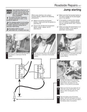 7
7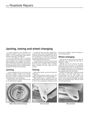 8
8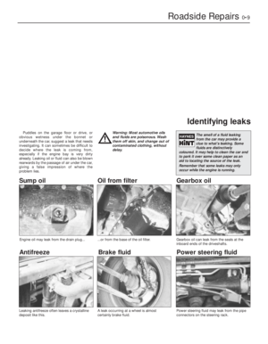 9
9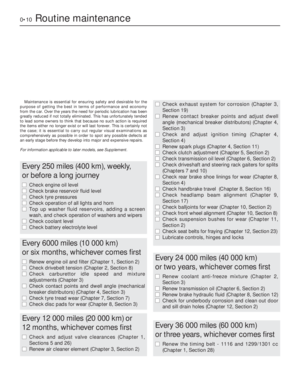 10
10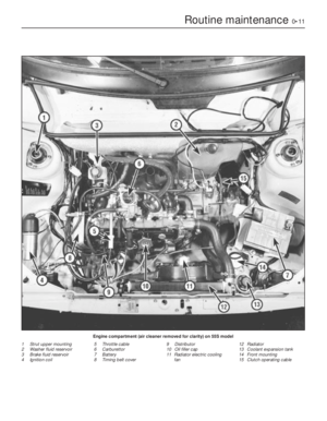 11
11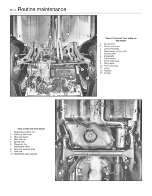 12
12 13
13 14
14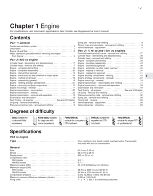 15
15 16
16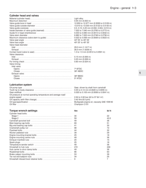 17
17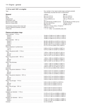 18
18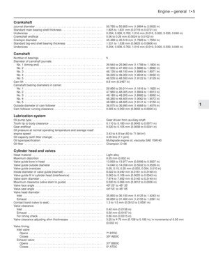 19
19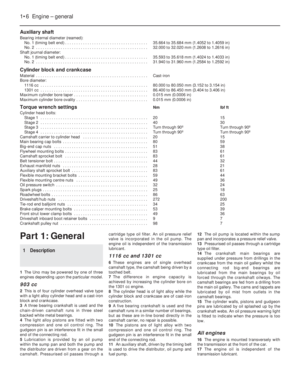 20
20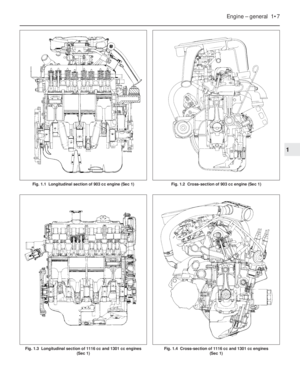 21
21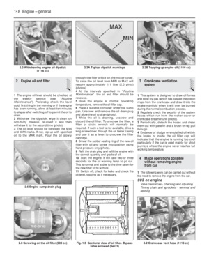 22
22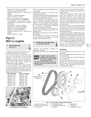 23
23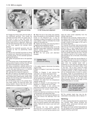 24
24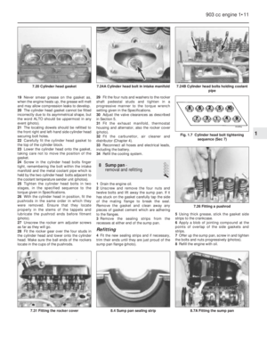 25
25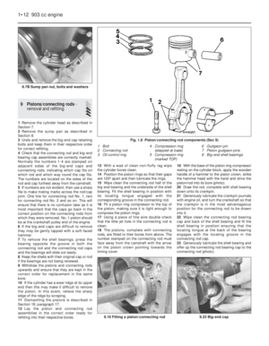 26
26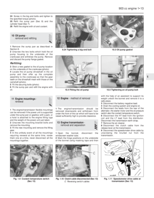 27
27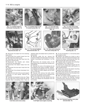 28
28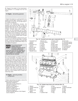 29
29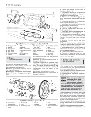 30
30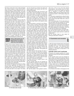 31
31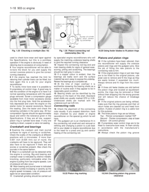 32
32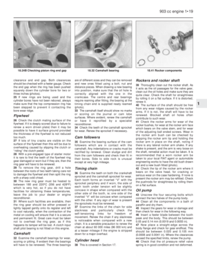 33
33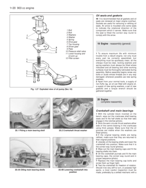 34
34 35
35 36
36 37
37 38
38 39
39 40
40 41
41 42
42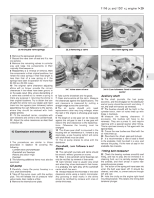 43
43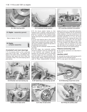 44
44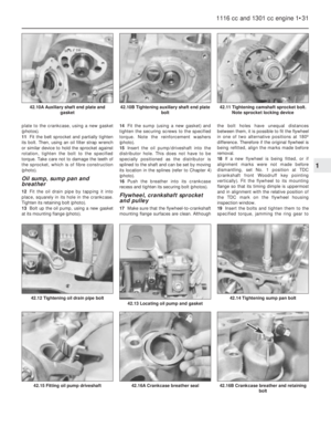 45
45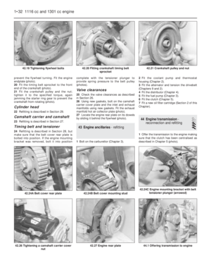 46
46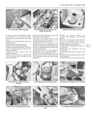 47
47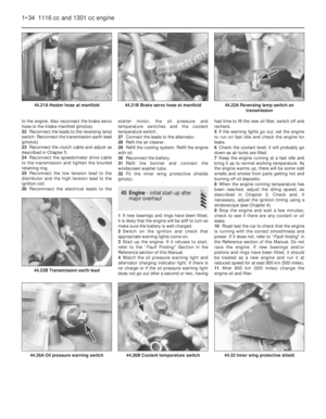 48
48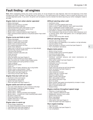 49
49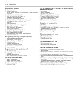 50
50 51
51 52
52 53
53 54
54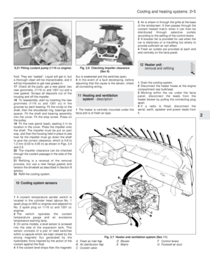 55
55 56
56 57
57 58
58 59
59 60
60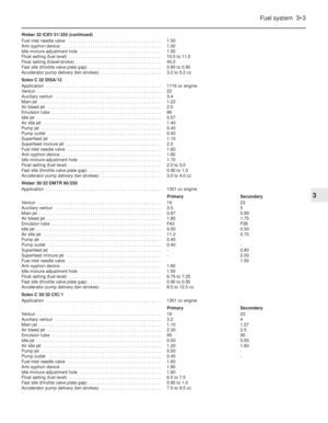 61
61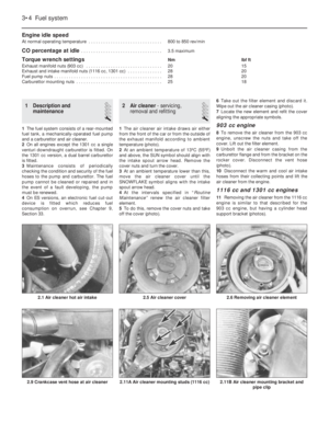 62
62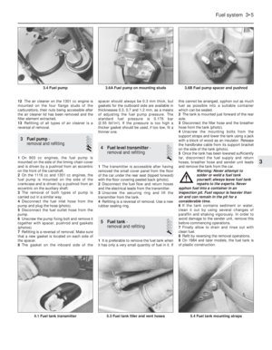 63
63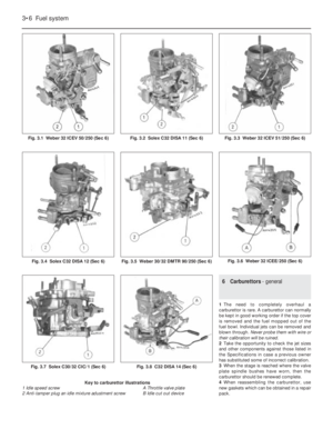 64
64 65
65 66
66 67
67 68
68 69
69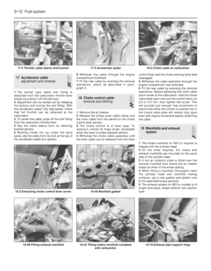 70
70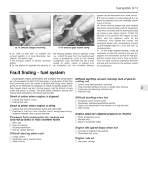 71
71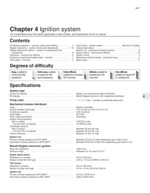 72
72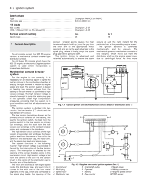 73
73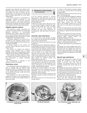 74
74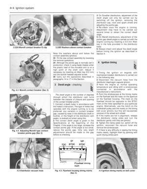 75
75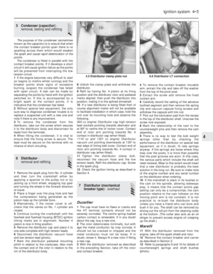 76
76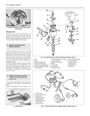 77
77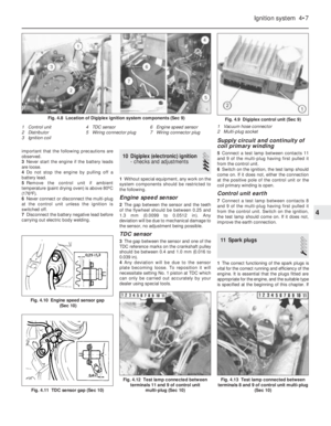 78
78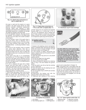 79
79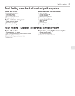 80
80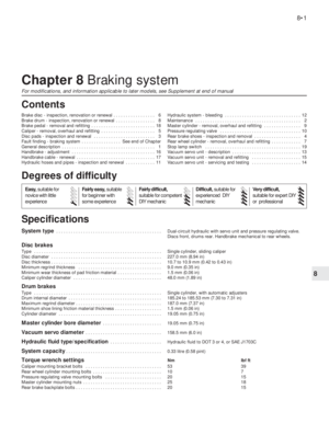 81
81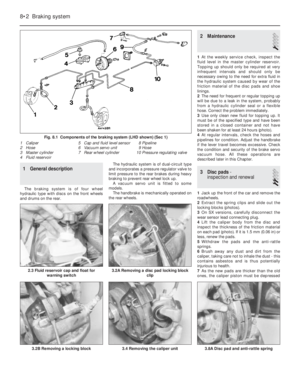 82
82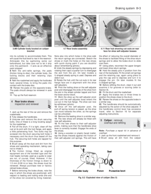 83
83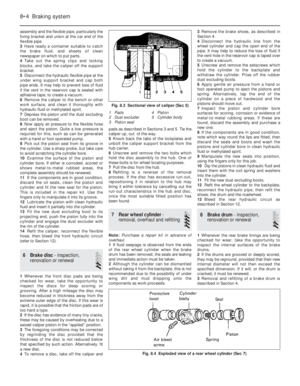 84
84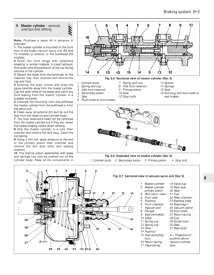 85
85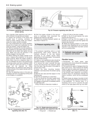 86
86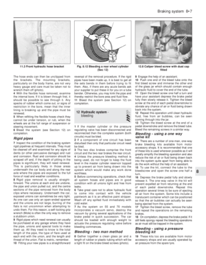 87
87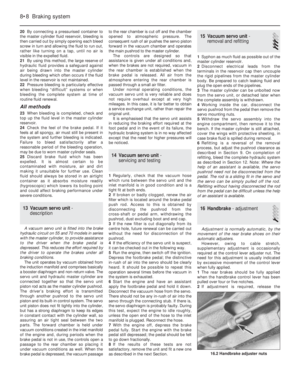 88
88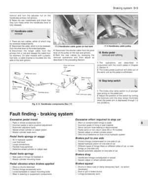 89
89 90
90 91
91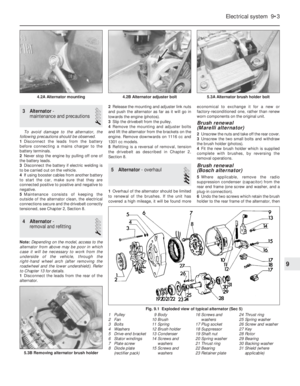 92
92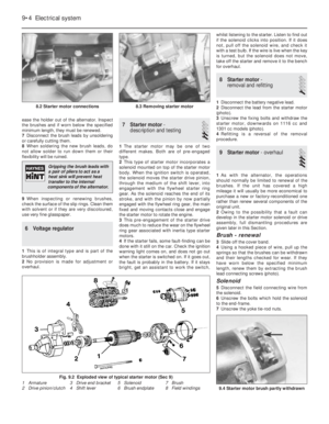 93
93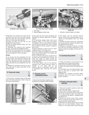 94
94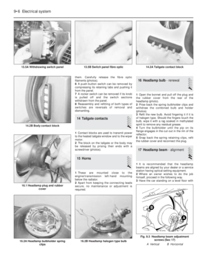 95
95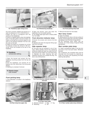 96
96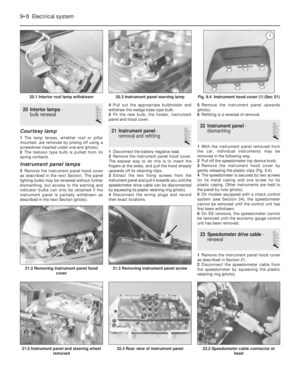 97
97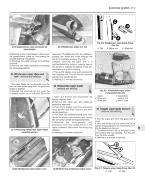 98
98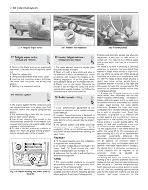 99
99 100
100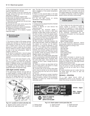 101
101 102
102 103
103 104
104 105
105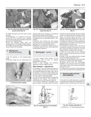 106
106 107
107 108
108 109
109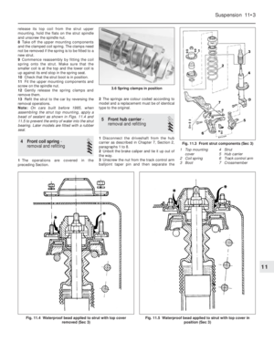 110
110 111
111 112
112 113
113 114
114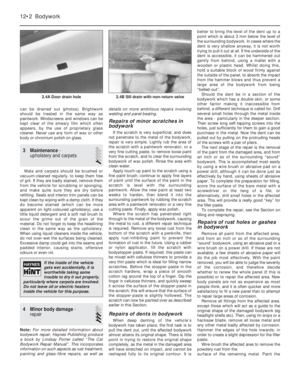 115
115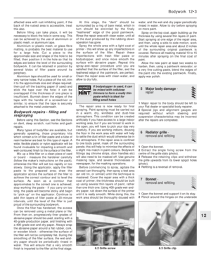 116
116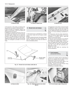 117
117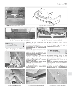 118
118 119
119 120
120 121
121 122
122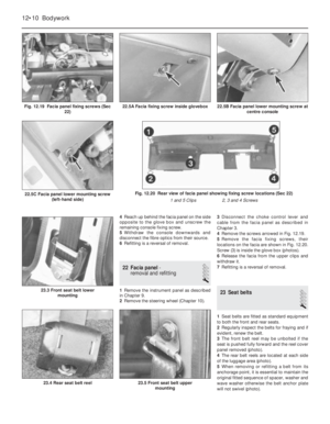 123
123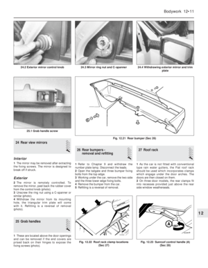 124
124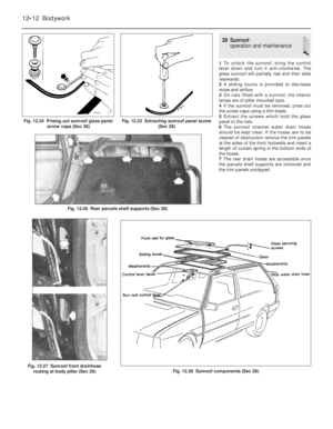 125
125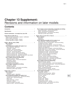 126
126 127
127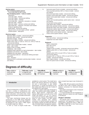 128
128 129
129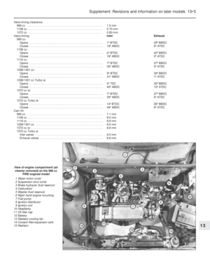 130
130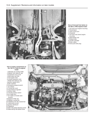 131
131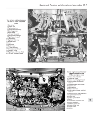 132
132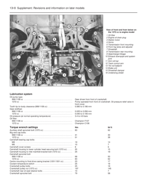 133
133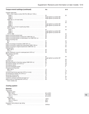 134
134 135
135 136
136 137
137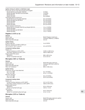 138
138 139
139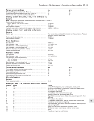 140
140 141
141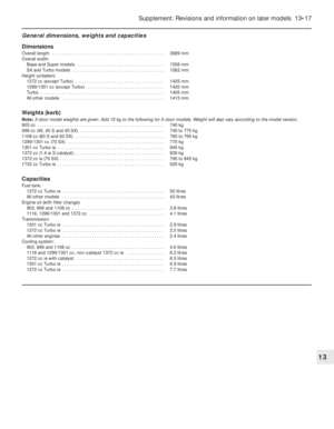 142
142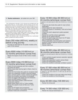 143
143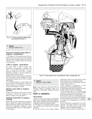 144
144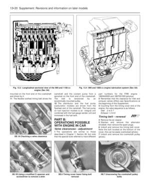 145
145 146
146 147
147 148
148 149
149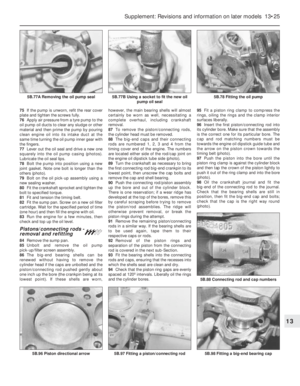 150
150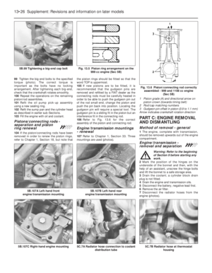 151
151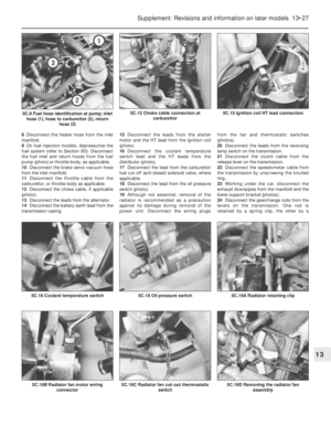 152
152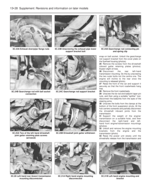 153
153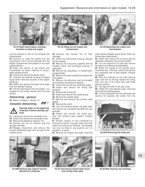 154
154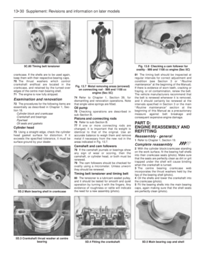 155
155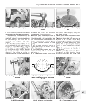 156
156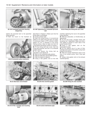 157
157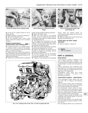 158
158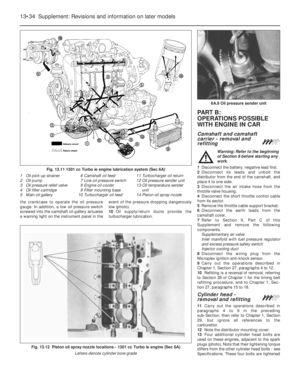 159
159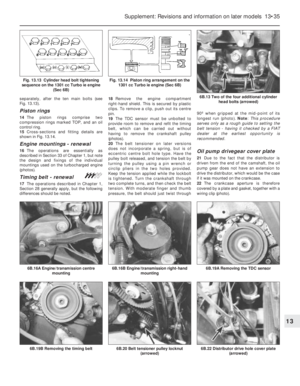 160
160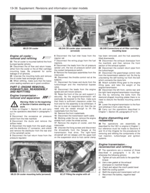 161
161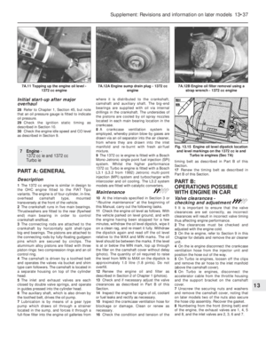 162
162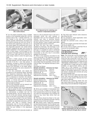 163
163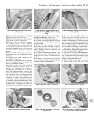 164
164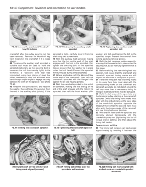 165
165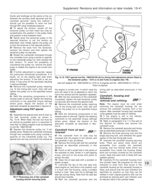 166
166 167
167 168
168 169
169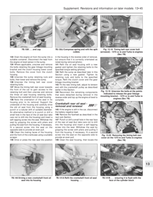 170
170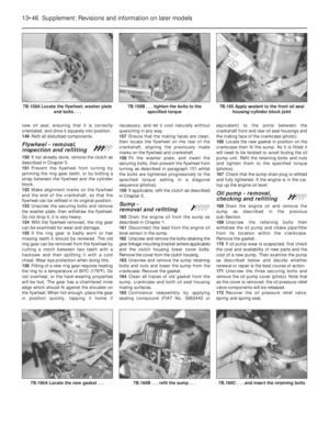 171
171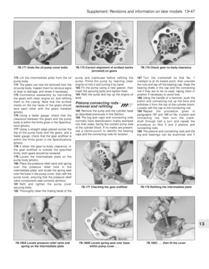 172
172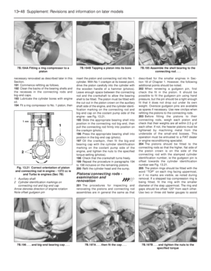 173
173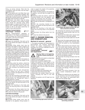 174
174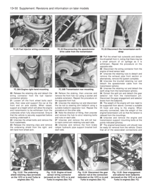 175
175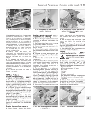 176
176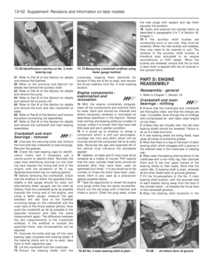 177
177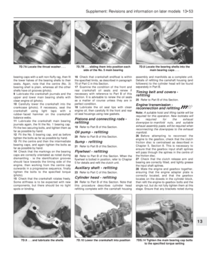 178
178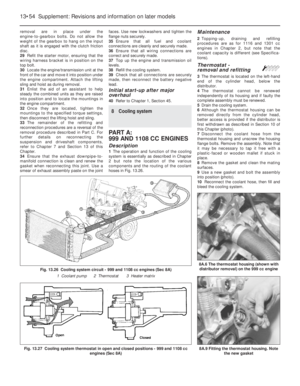 179
179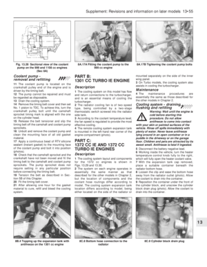 180
180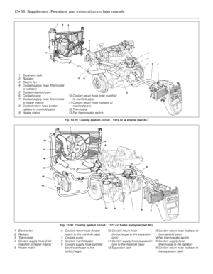 181
181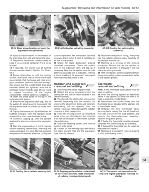 182
182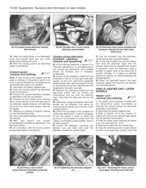 183
183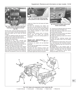 184
184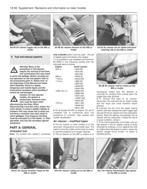 185
185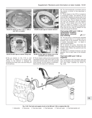 186
186 187
187 188
188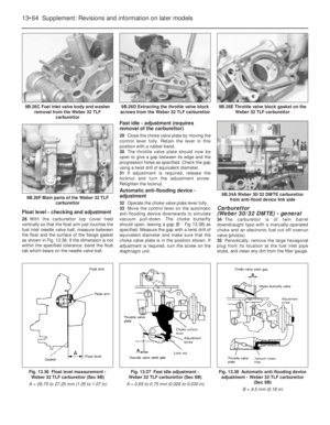 189
189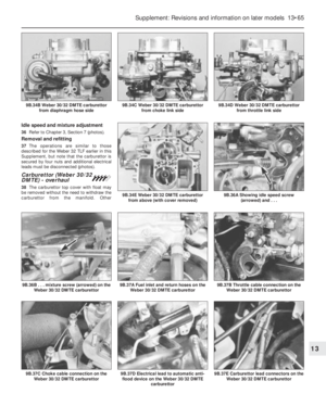 190
190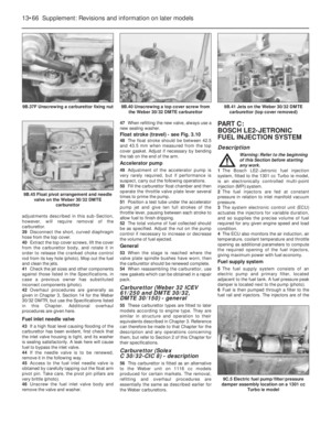 191
191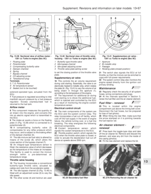 192
192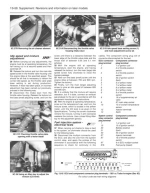 193
193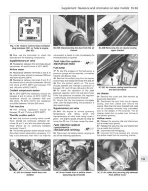 194
194 195
195 196
196 197
197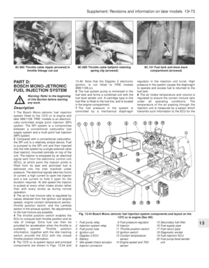 198
198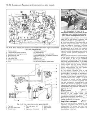 199
199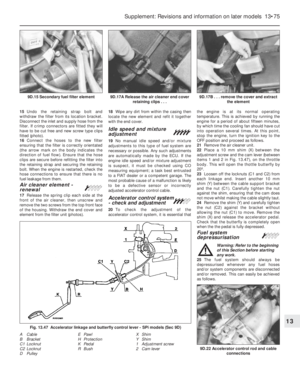 200
200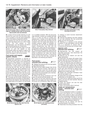 201
201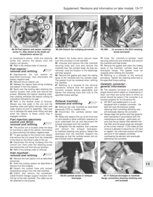 202
202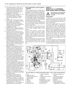 203
203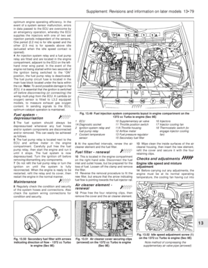 204
204 205
205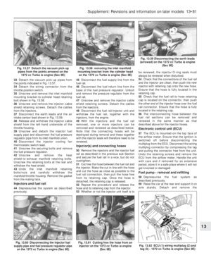 206
206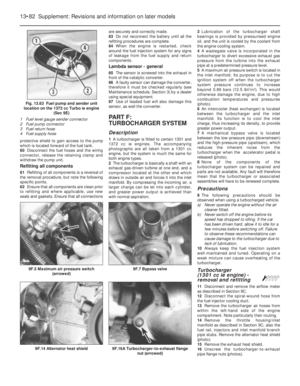 207
207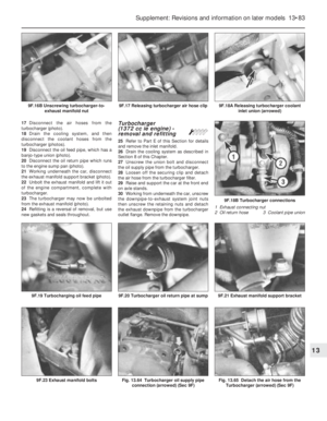 208
208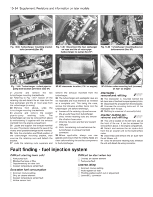 209
209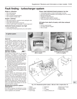 210
210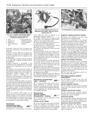 211
211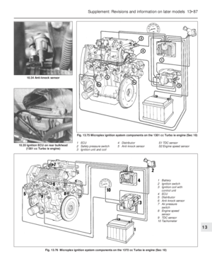 212
212 213
213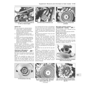 214
214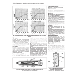 215
215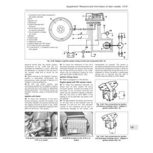 216
216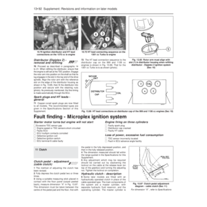 217
217 218
218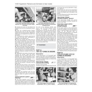 219
219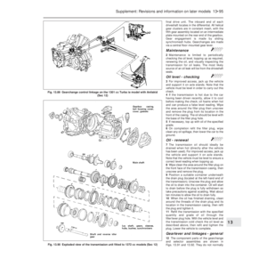 220
220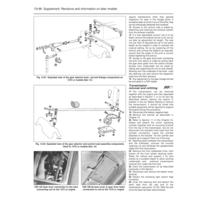 221
221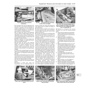 222
222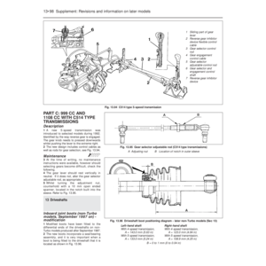 223
223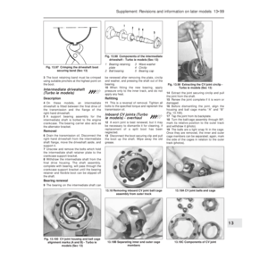 224
224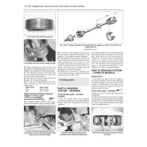 225
225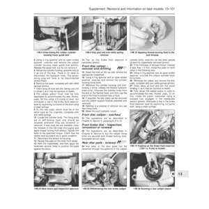 226
226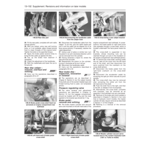 227
227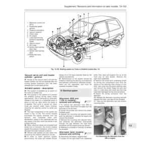 228
228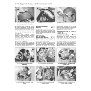 229
229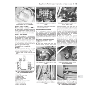 230
230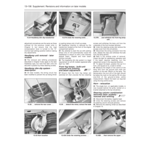 231
231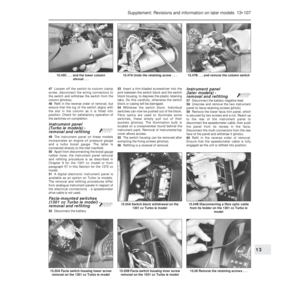 232
232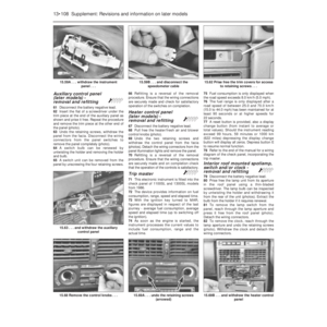 233
233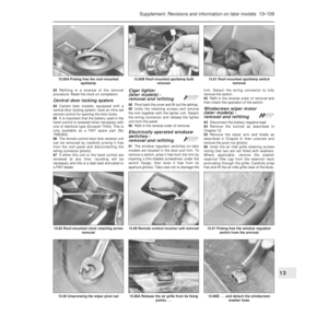 234
234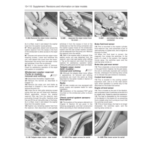 235
235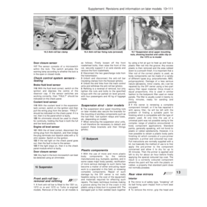 236
236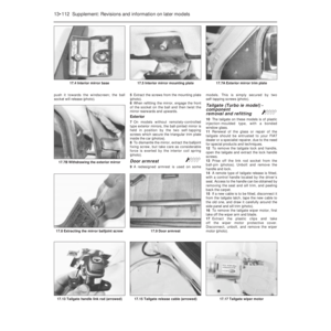 237
237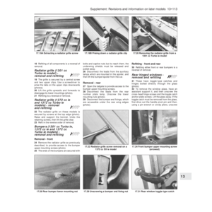 238
238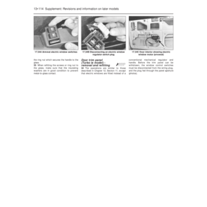 239
239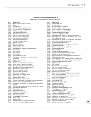 240
240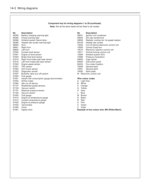 241
241 242
242 243
243 244
244 245
245 246
246 247
247 248
248 249
249 250
250 251
251 252
252 253
253 254
254 255
255 256
256 257
257 258
258 259
259 260
260 261
261 262
262 263
263 264
264 265
265 266
266 267
267 268
268 269
269 270
270 271
271 272
272 273
273 274
274 275
275 276
276 277
277 278
278 279
279 280
280 281
281 282
282 283
283 284
284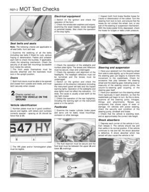 285
285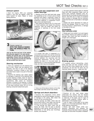 286
286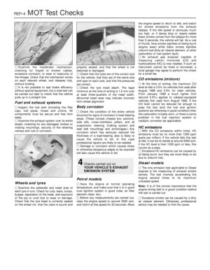 287
287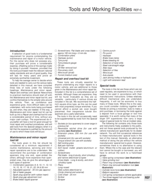 288
288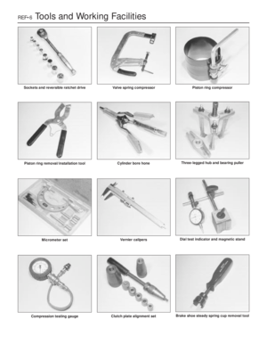 289
289 290
290 291
291 292
292 293
293 294
294 295
295 296
296 297
297 298
298 299
299 300
300 301
301 302
302